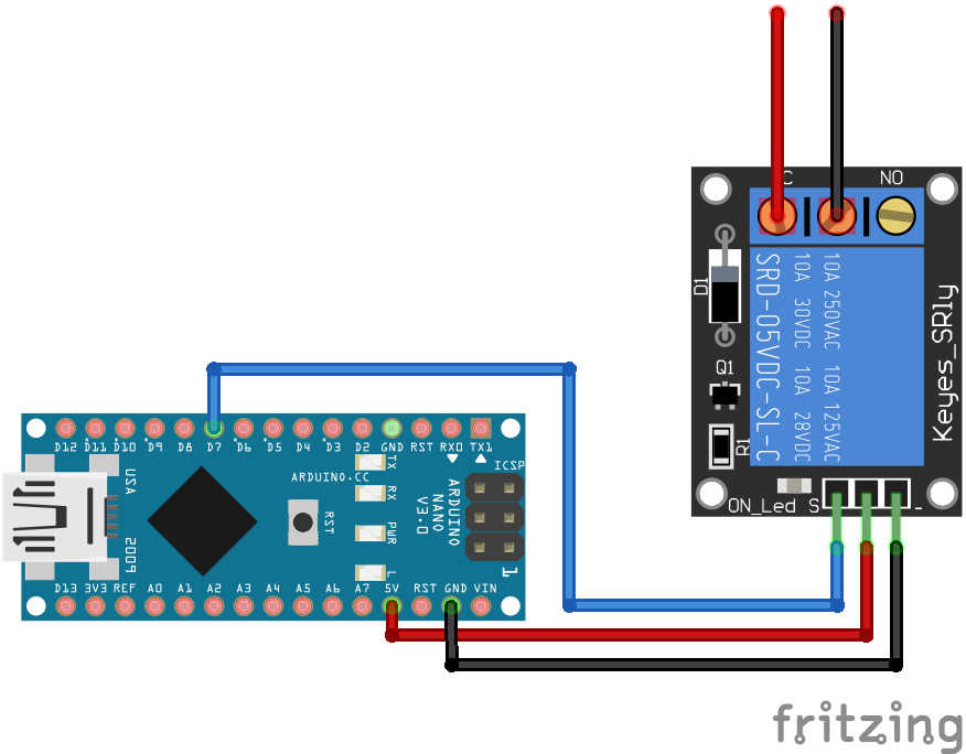
Relais Module Arduino Nano
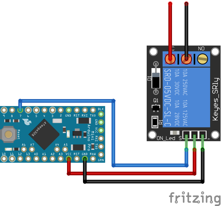
Relais Module Arduino Pro Mini
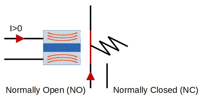
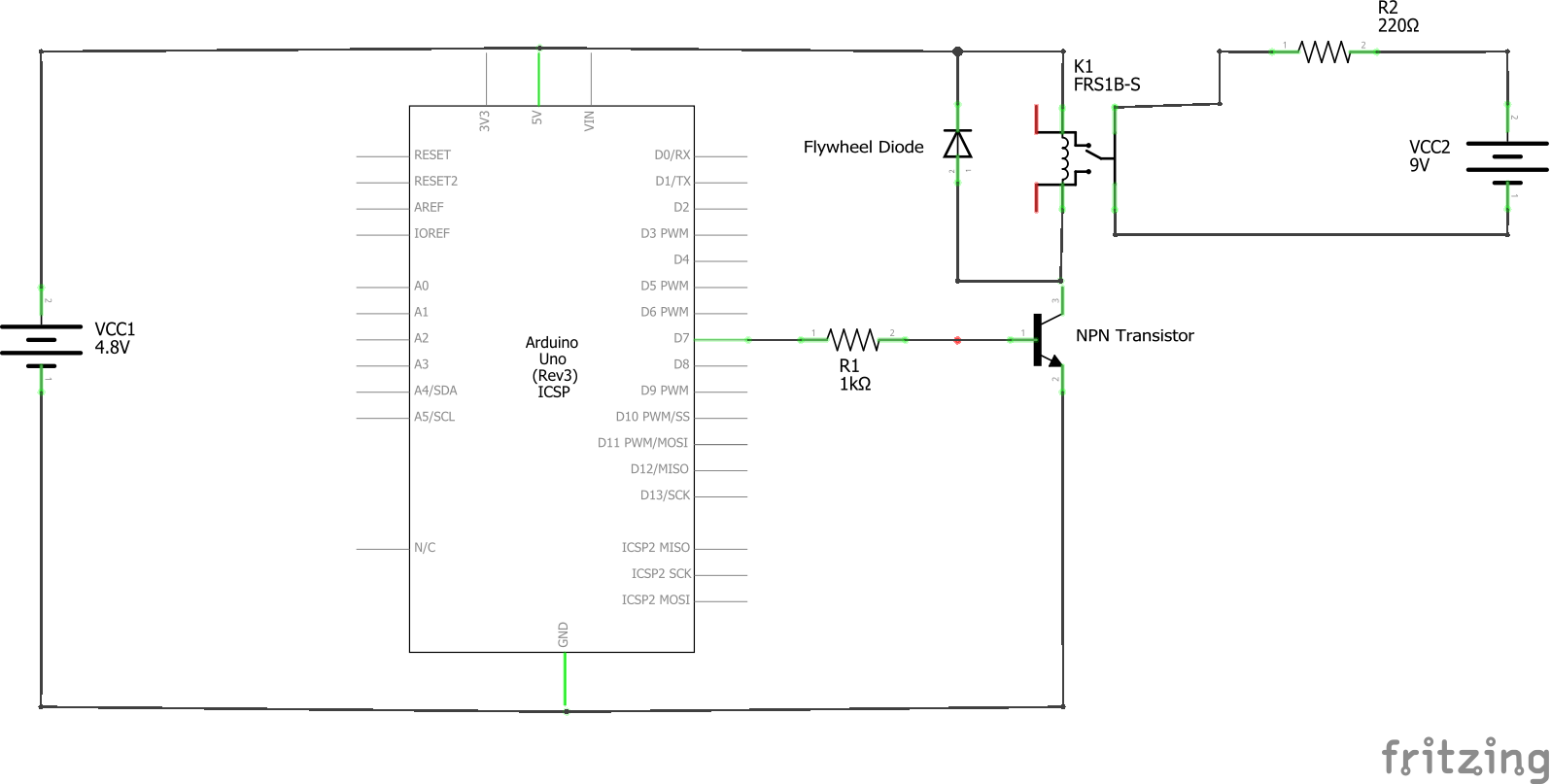
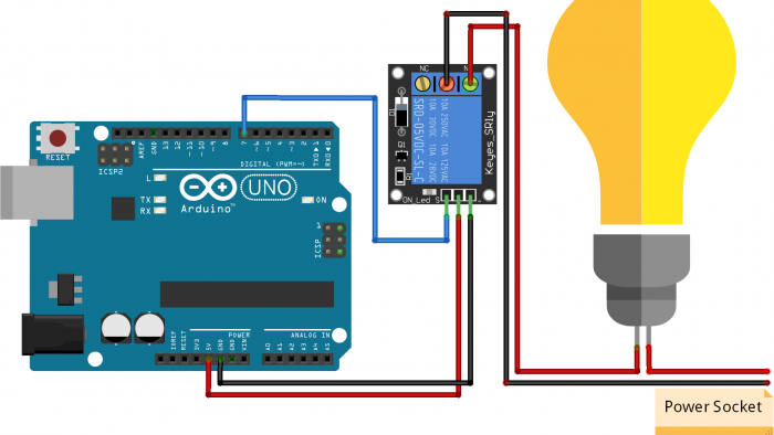
Relais Module Arduino Uno
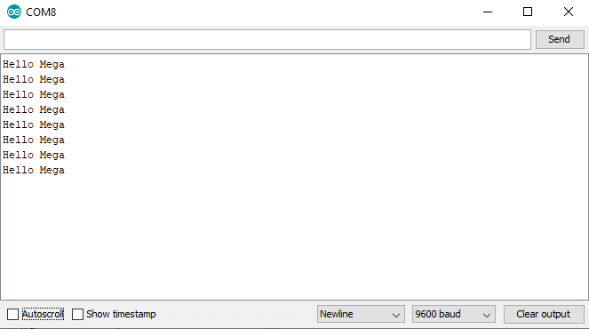
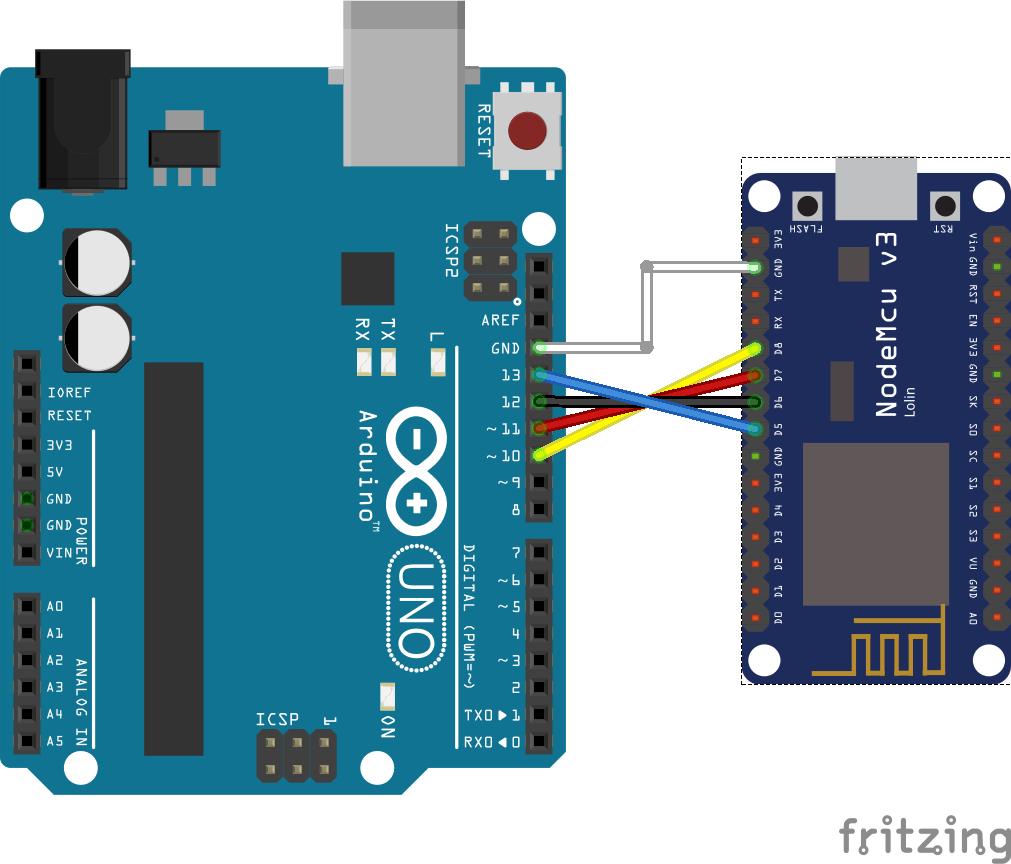
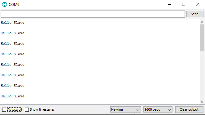
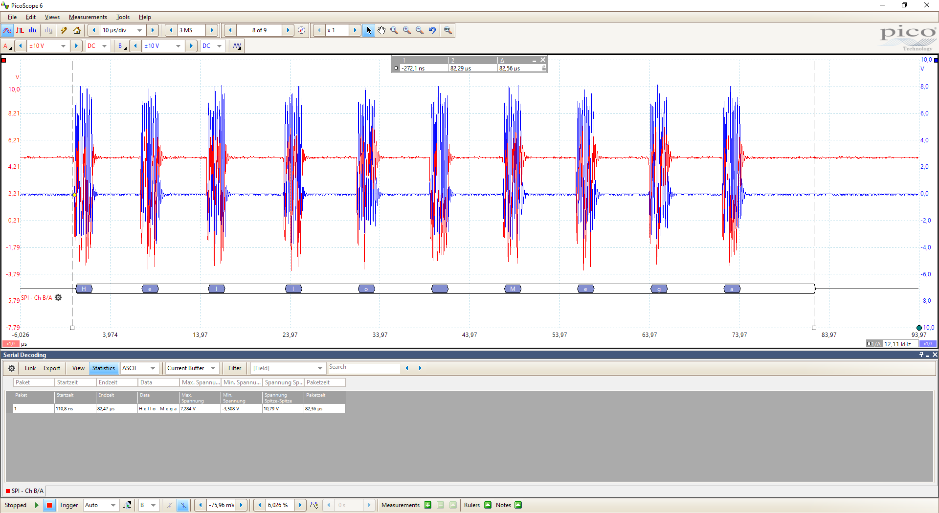
Relais Module Arduino Mega
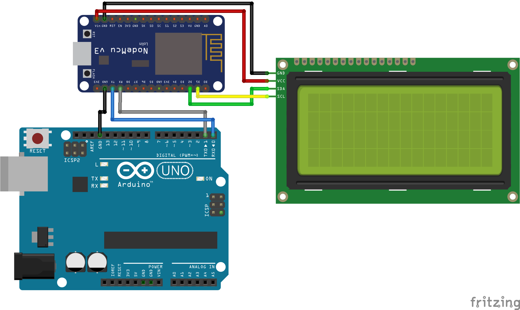
Relais Module ESP32 NodeMCU
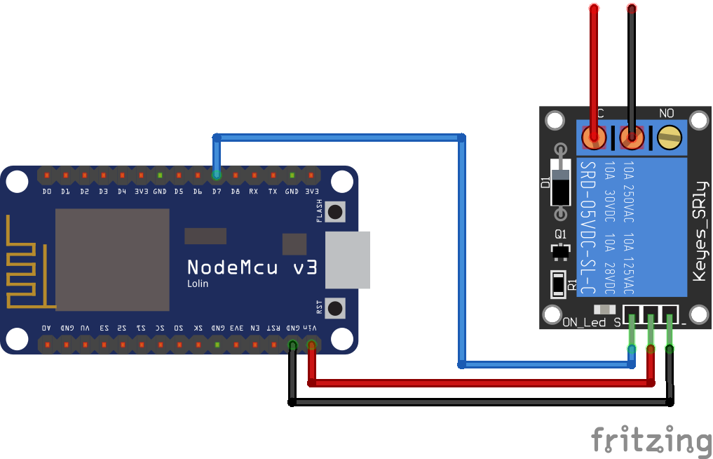
Relais Module NodeMCU
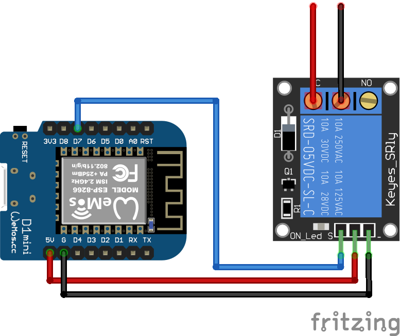
Relais Module ESP8266 WeMos D1 Mini
Relais Module Arduino Nano
Relais Module Arduino Pro Mini
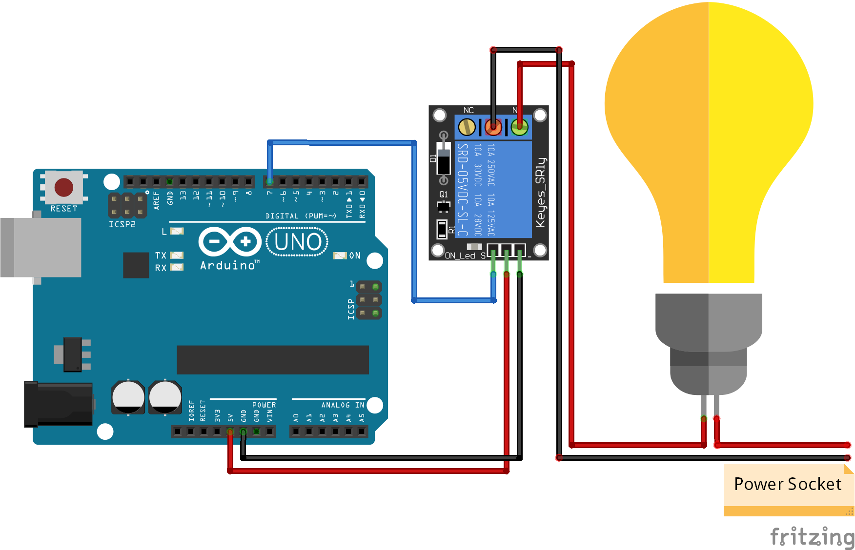
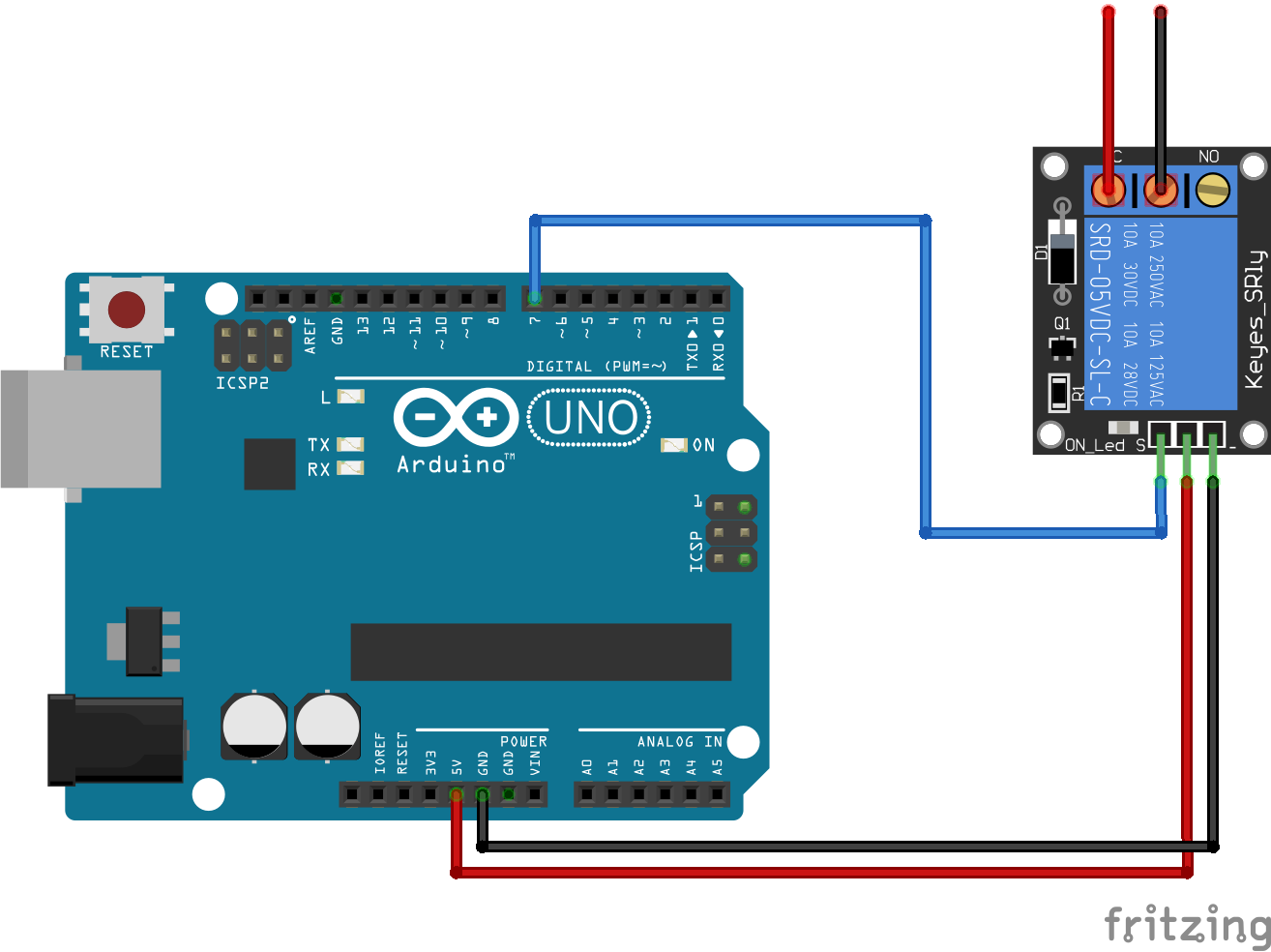
Relais Module Arduino Uno
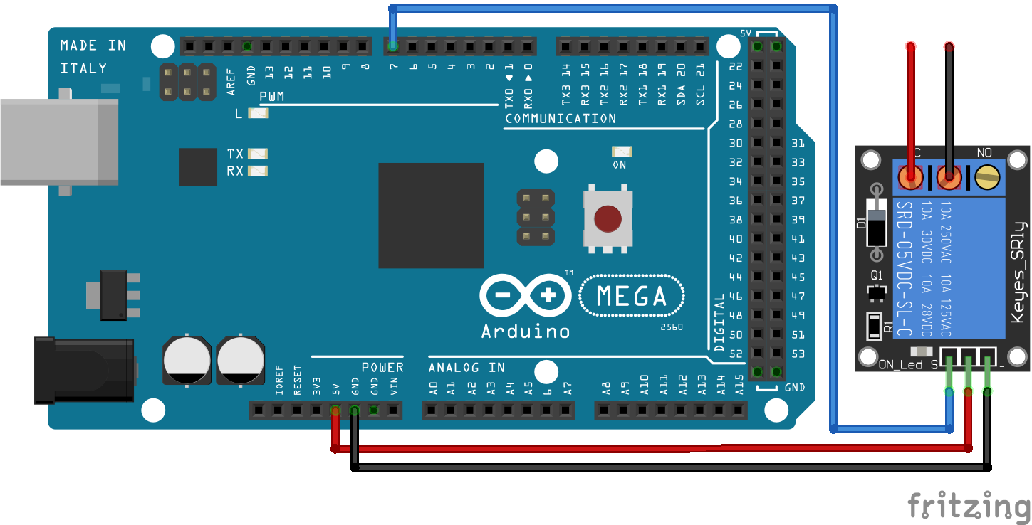
Relais Module Arduino Mega
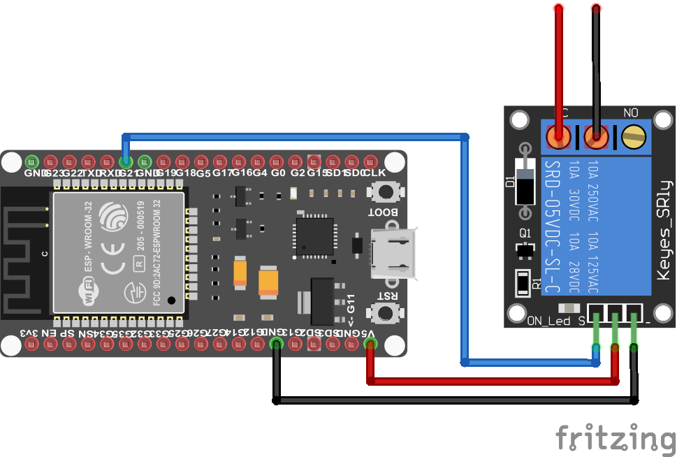
Relais Module ESP32 NodeMCU
Relais Module NodeMCU
Relais Module ESP8266 WeMos D1 Mini
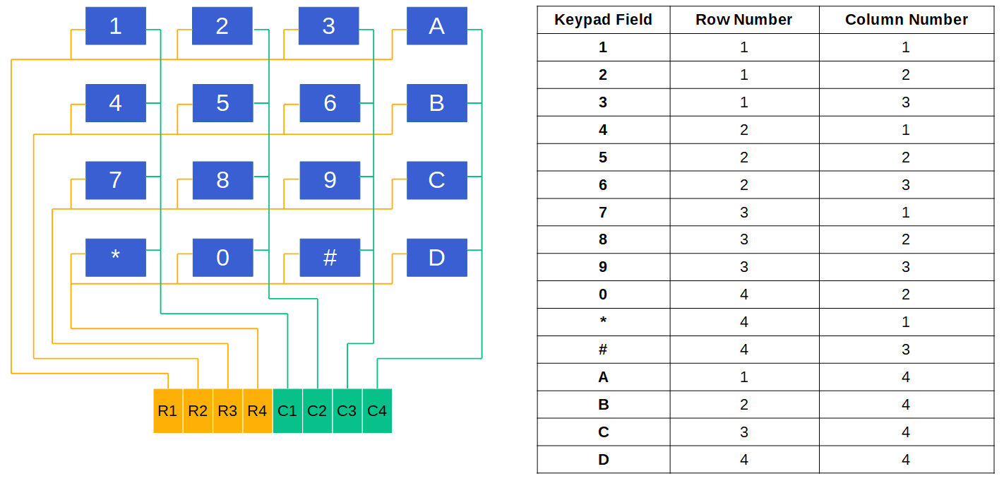
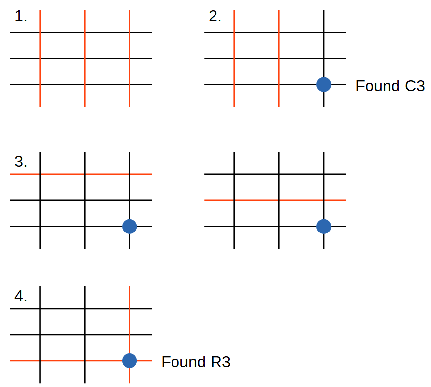

Keypad Arduino Nano
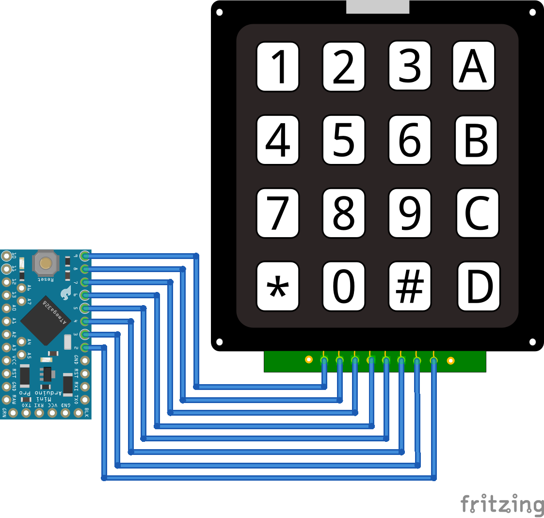
Keypad Arduino Pro Mini
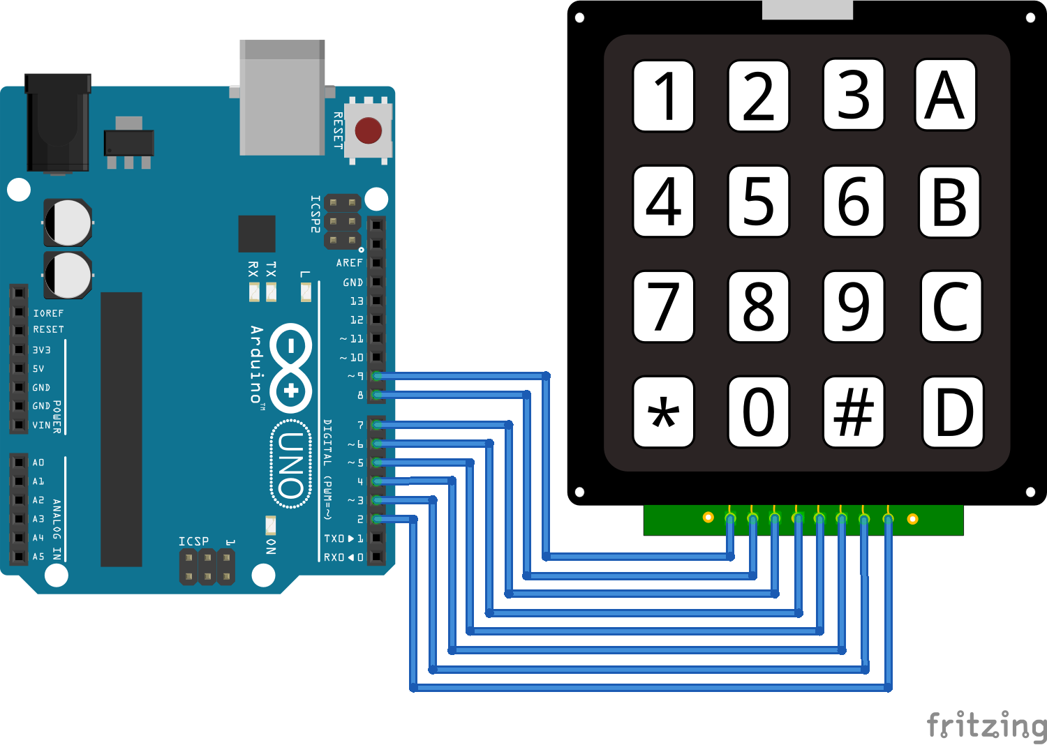
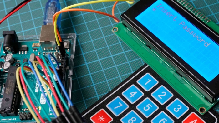
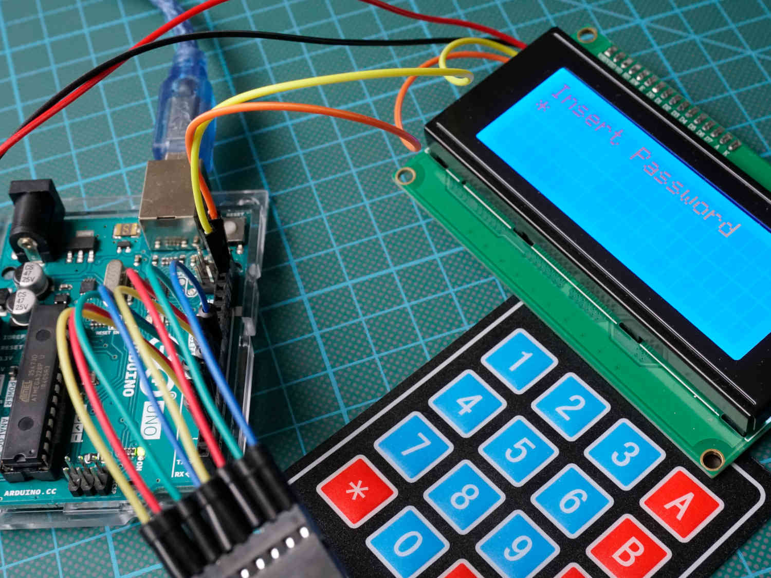
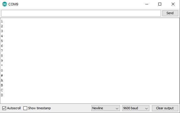
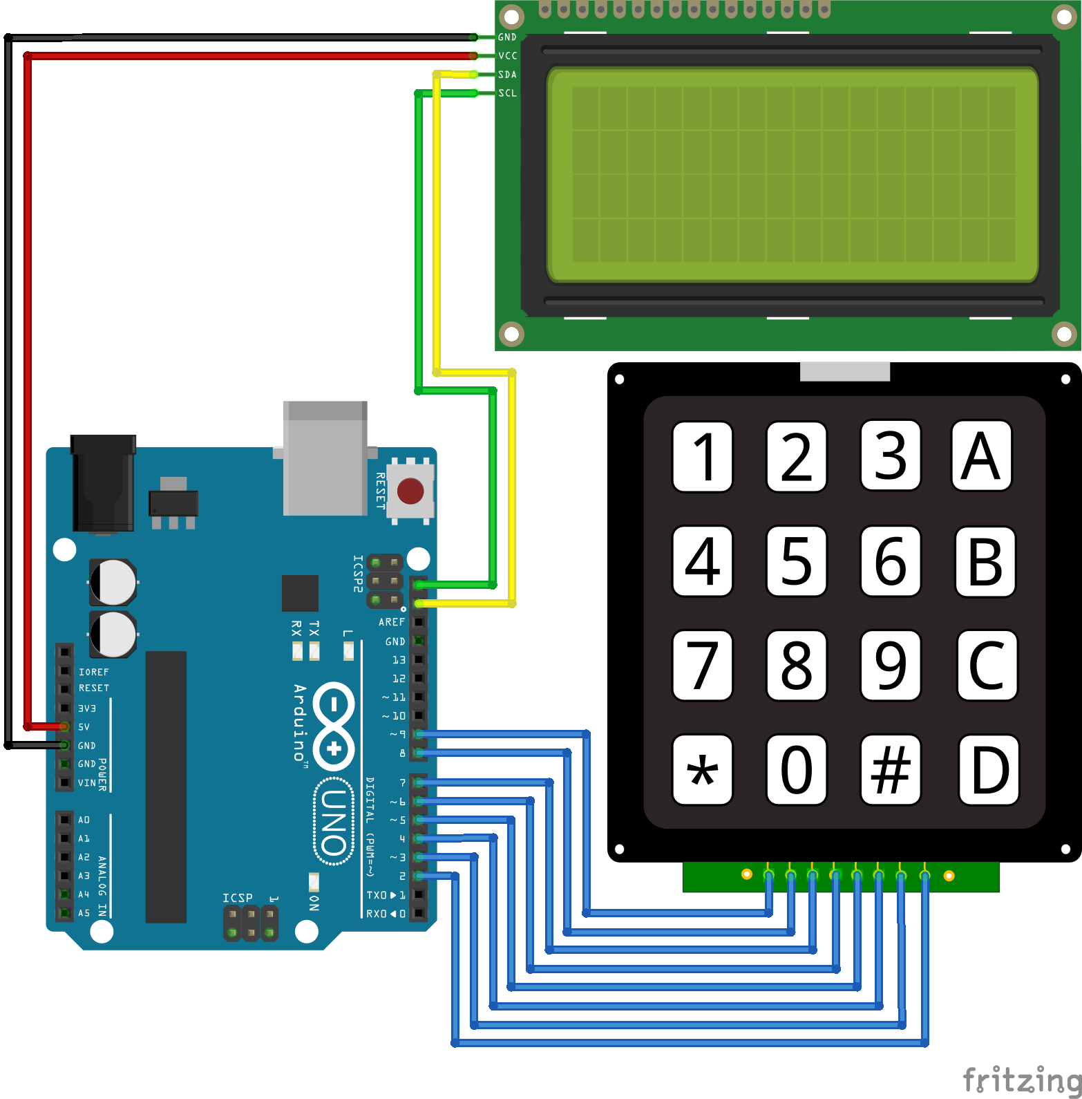
Keypad Arduino Uno
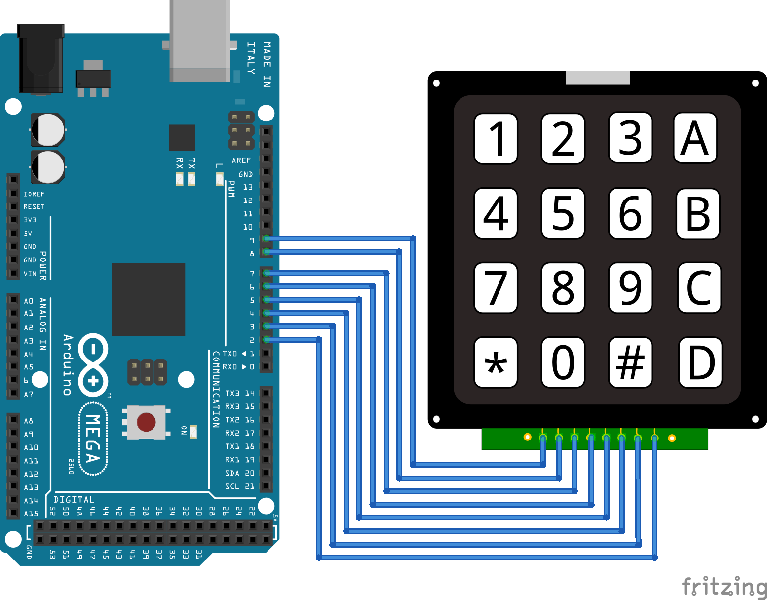
Keypad Arduino Mega
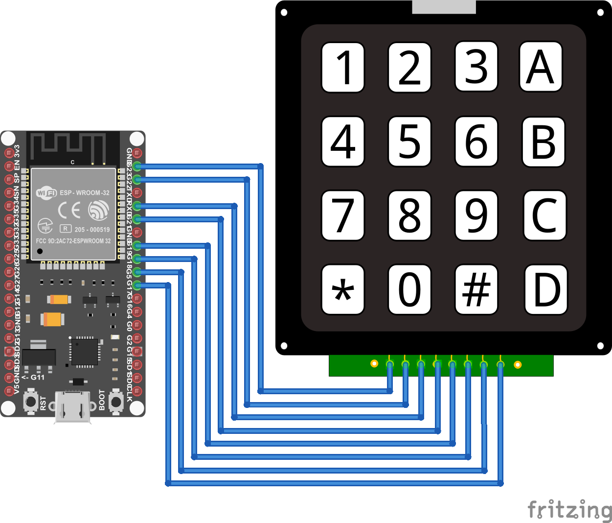
Keypad ESP32 NodeMCU
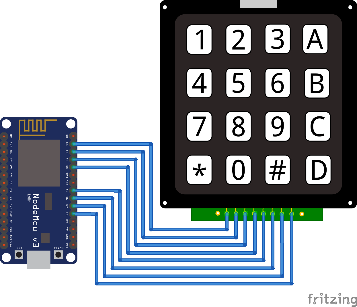
Keypad ESP8266
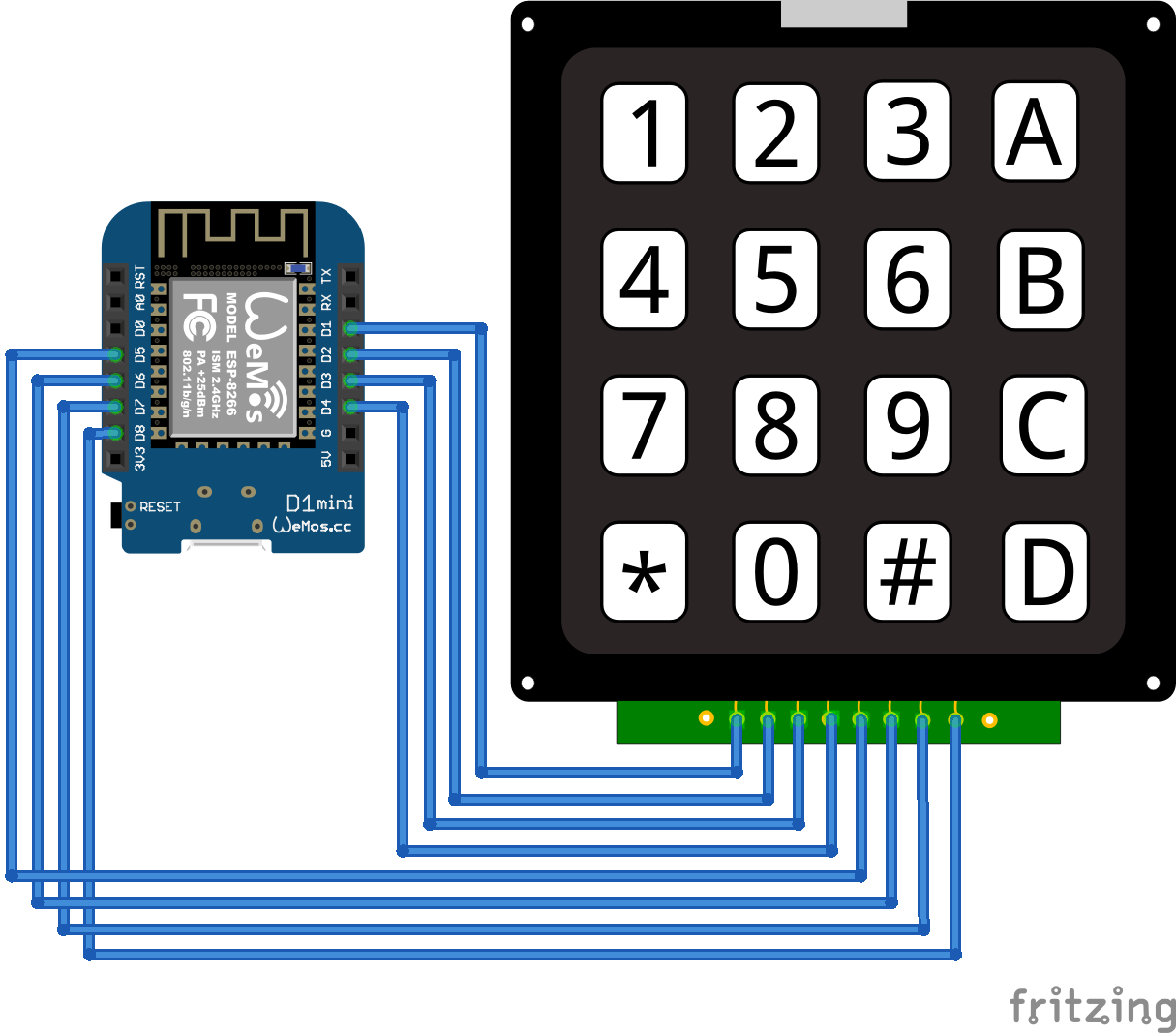
Keypad ESP8266 WeMos D1 Mini

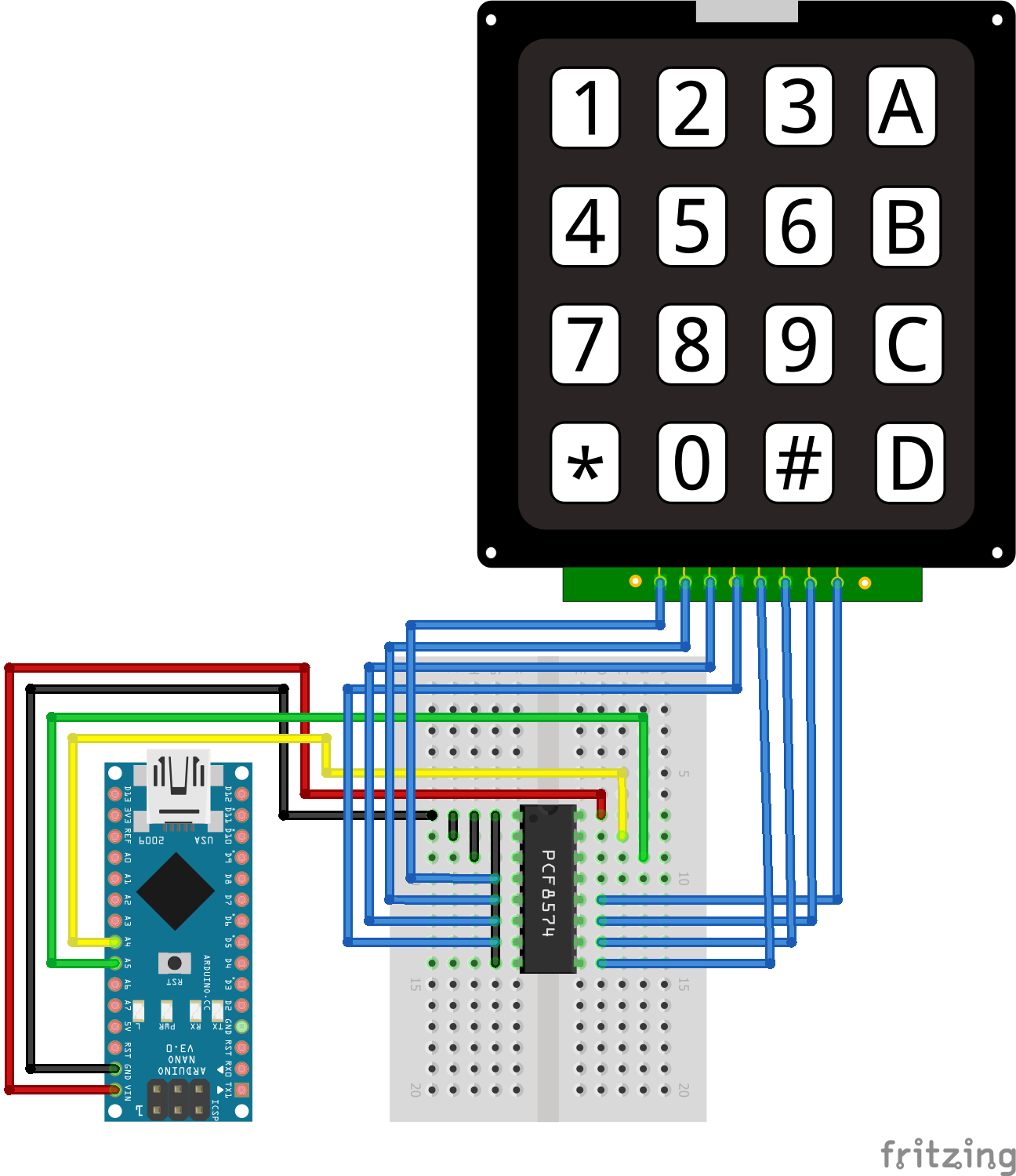
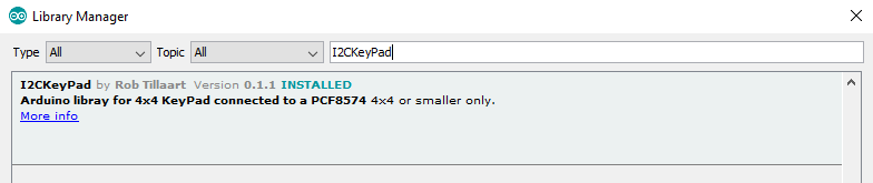
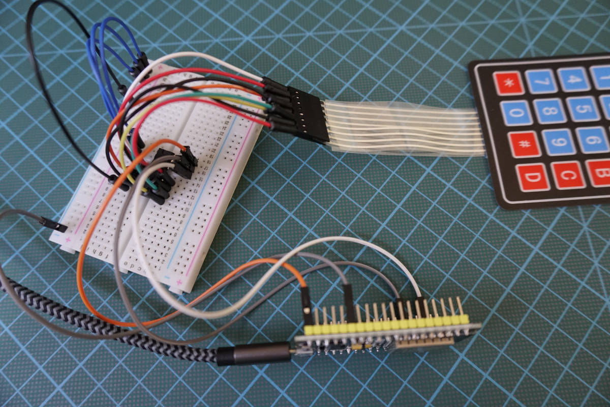
I2C Multiplexer Keypad Arduino Nano

I2C Multiplexer Keypad Arduino Pro Mini
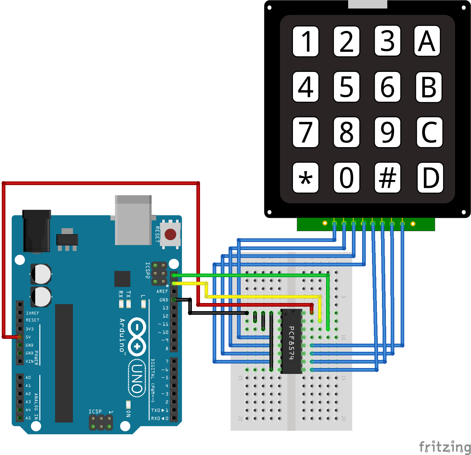
I2C Multiplexer Keypad Arduino Uno
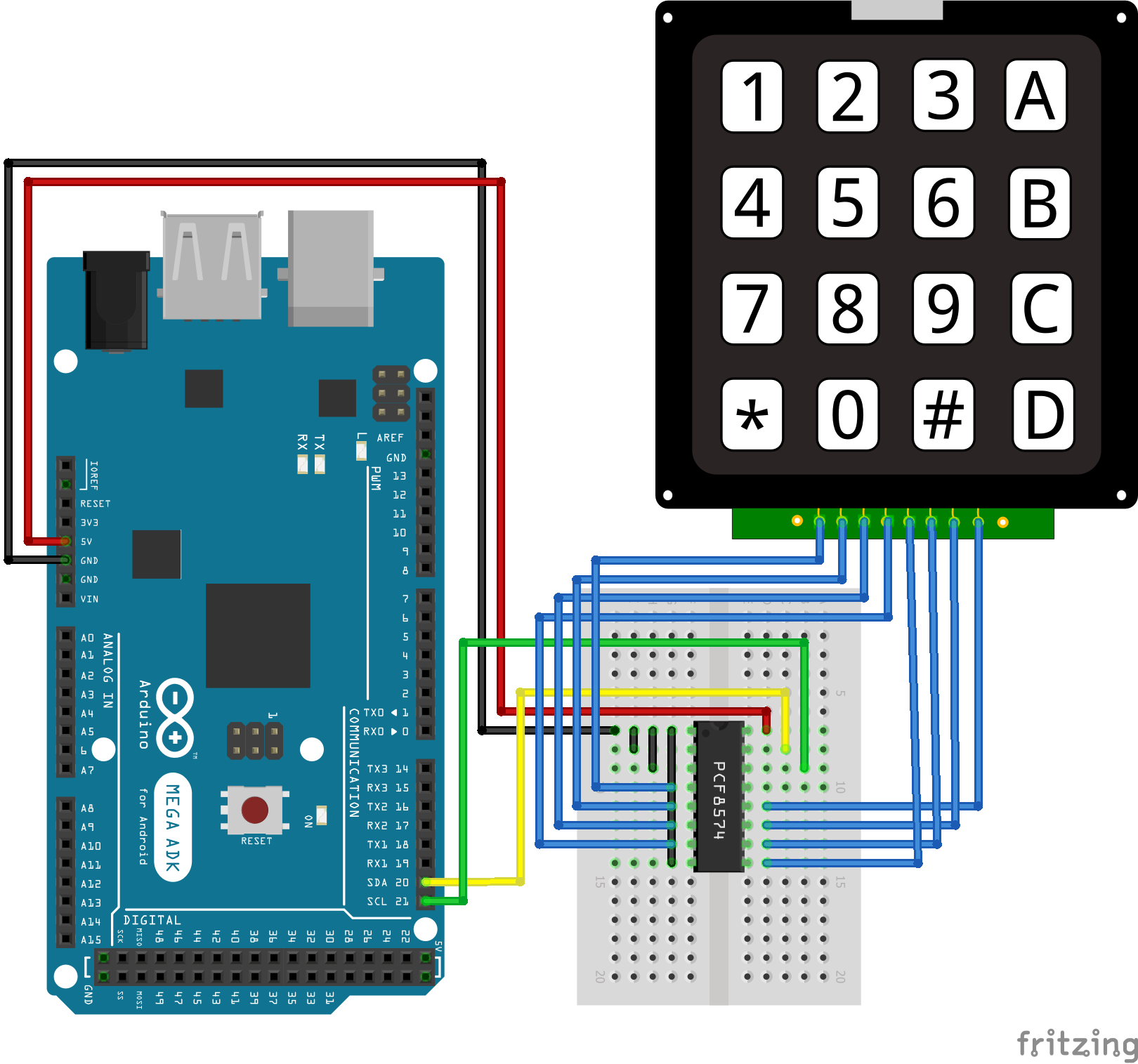
I2C Multiplexer Keypad Arduino Mega
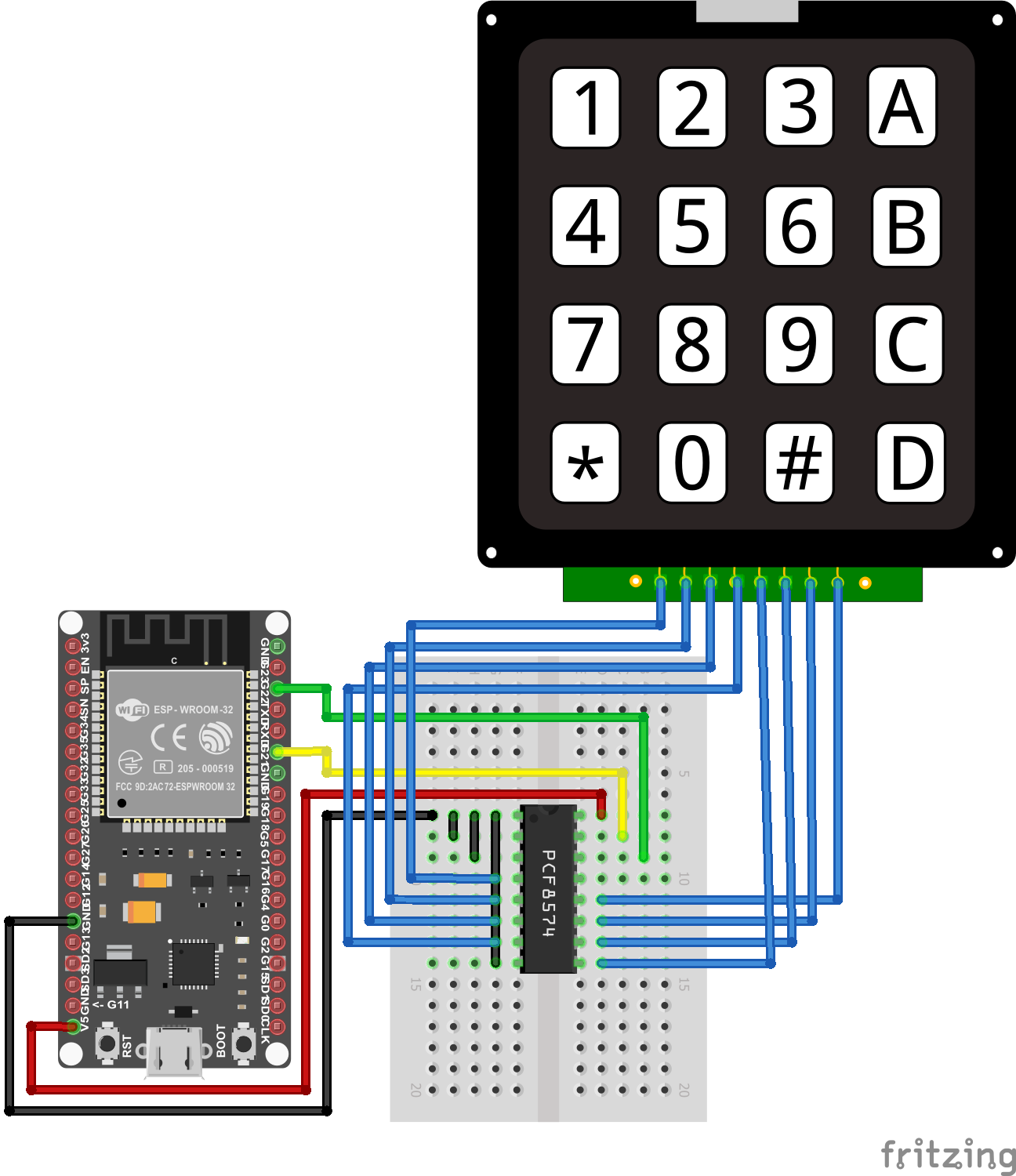
I2C Multiplexer Keypad ESP32 NodeMCU
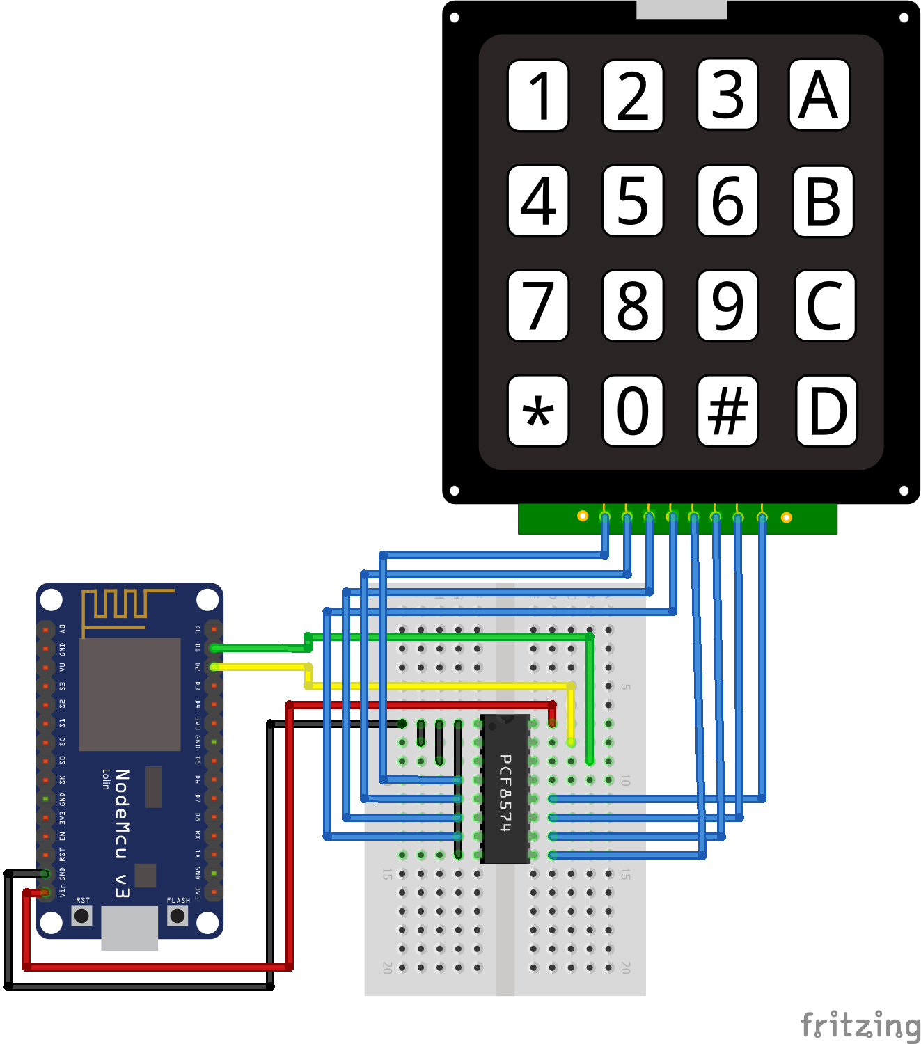
I2C Multiplexer Keypad ESP8266 NodeMCU
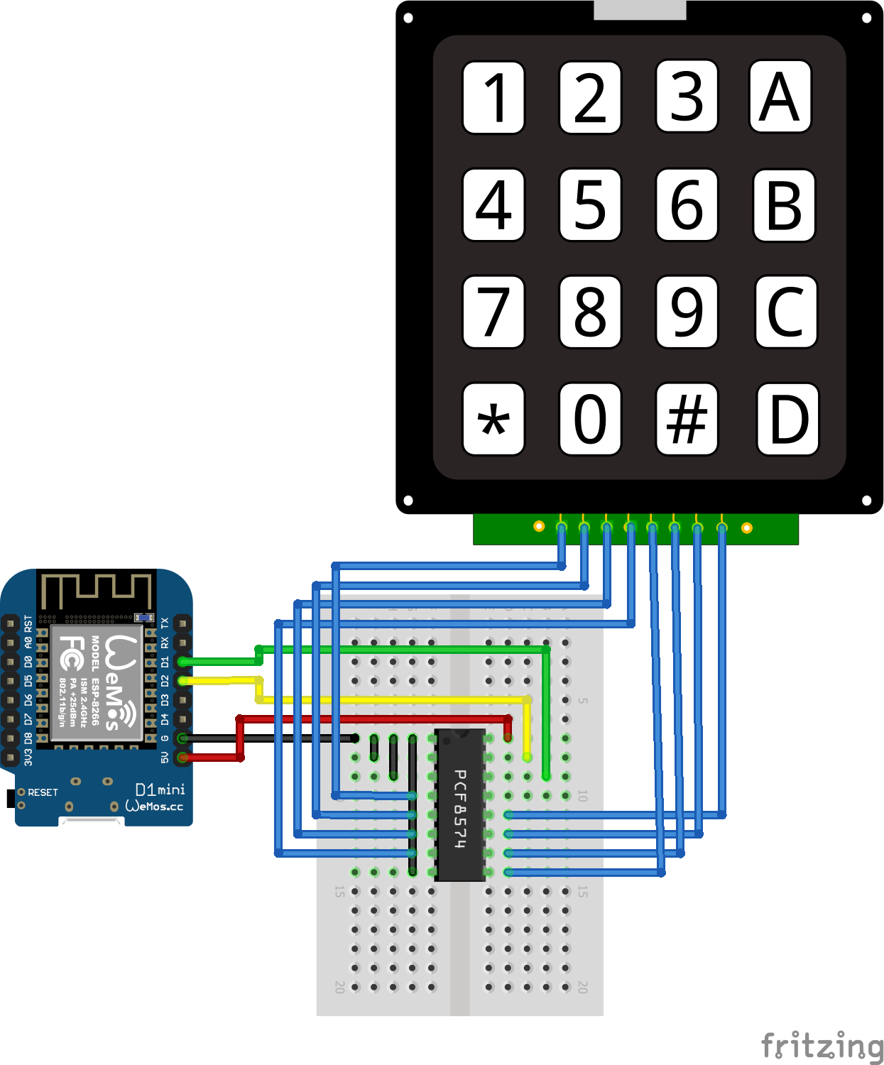
I2C Multiplexer Keypad ESP8266 WeMos D1 Mini
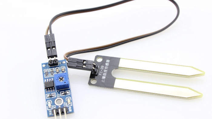
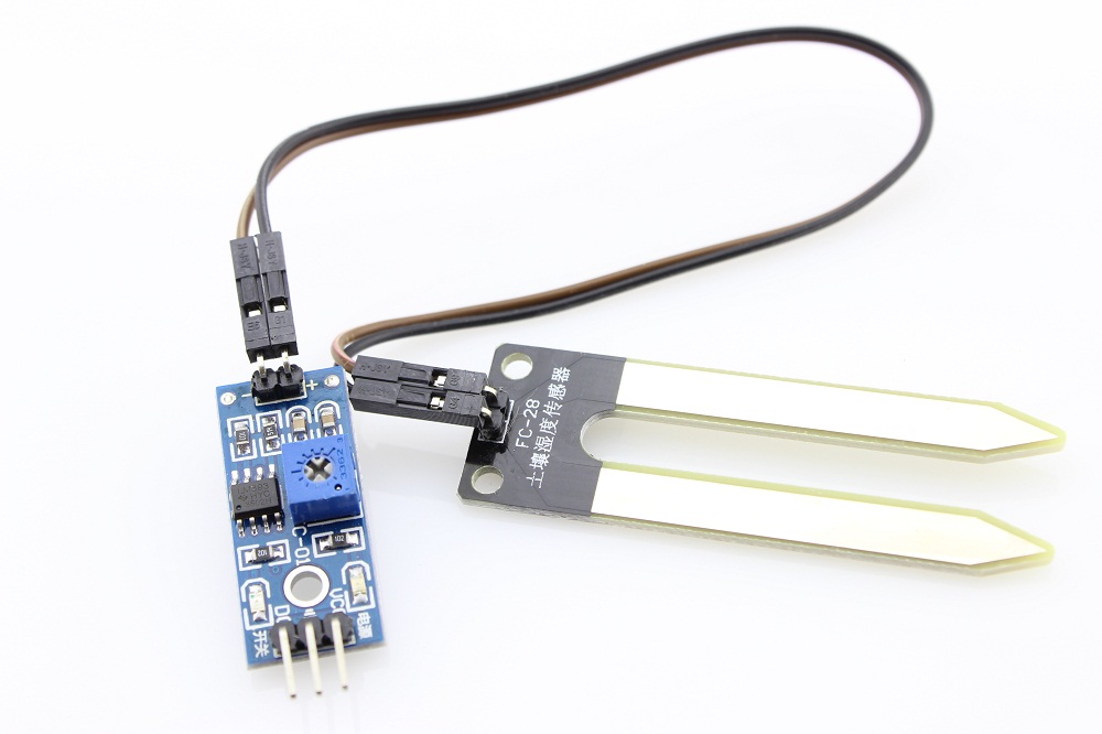
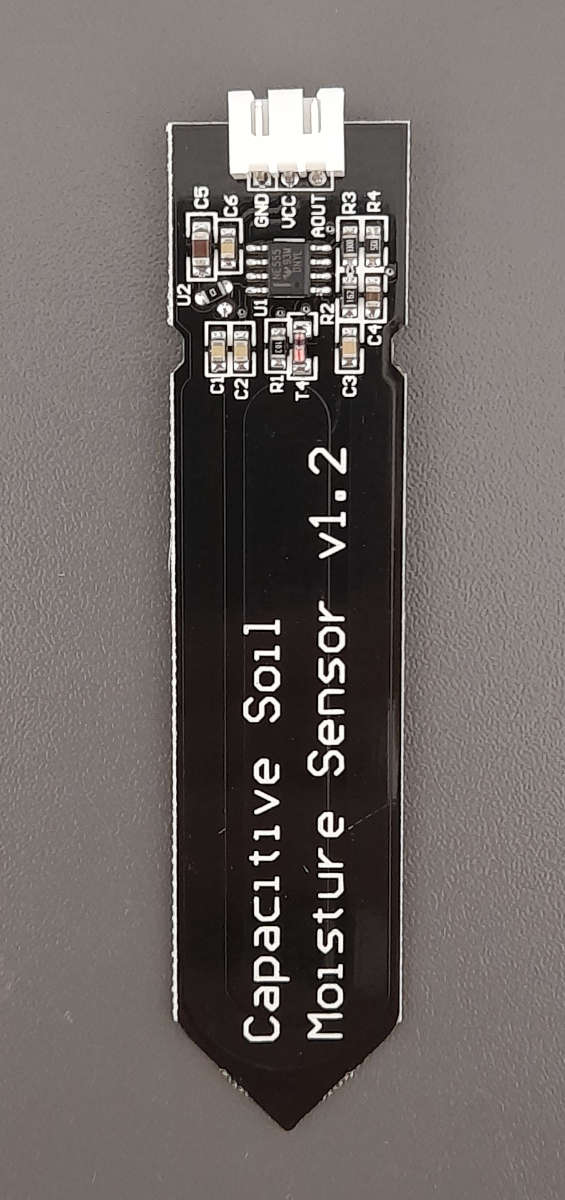
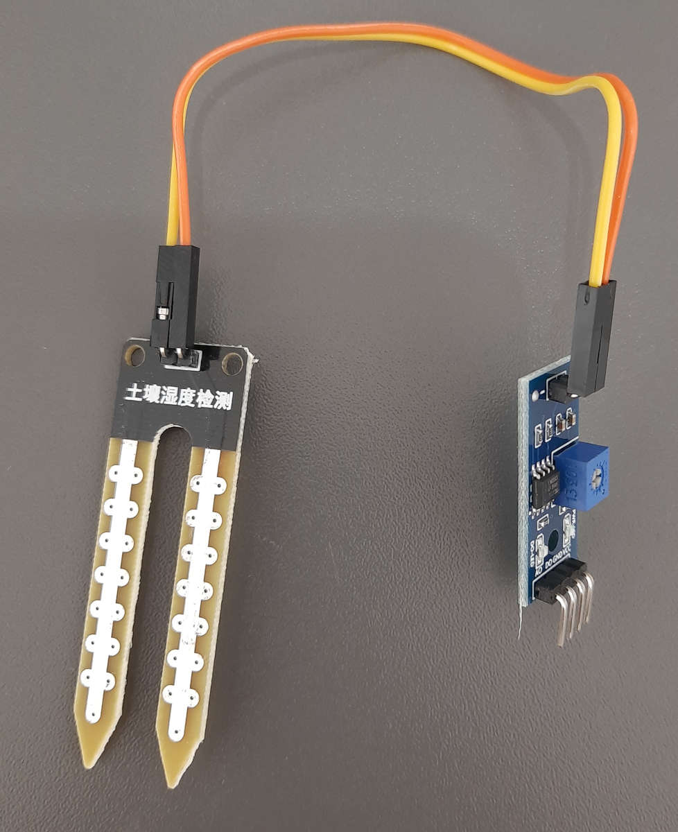
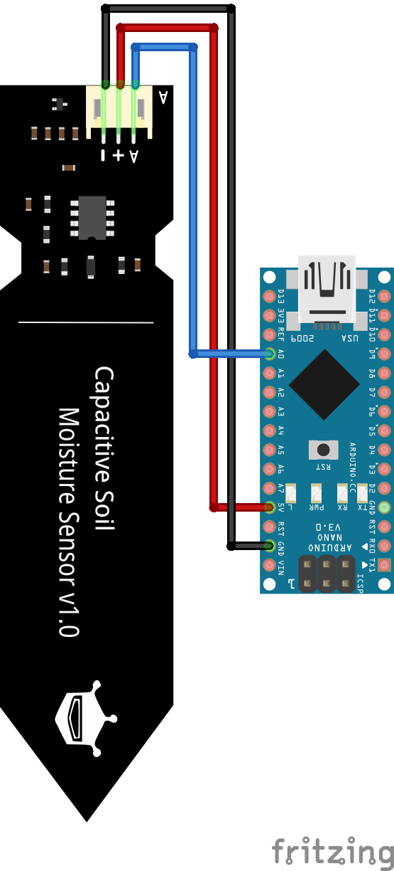
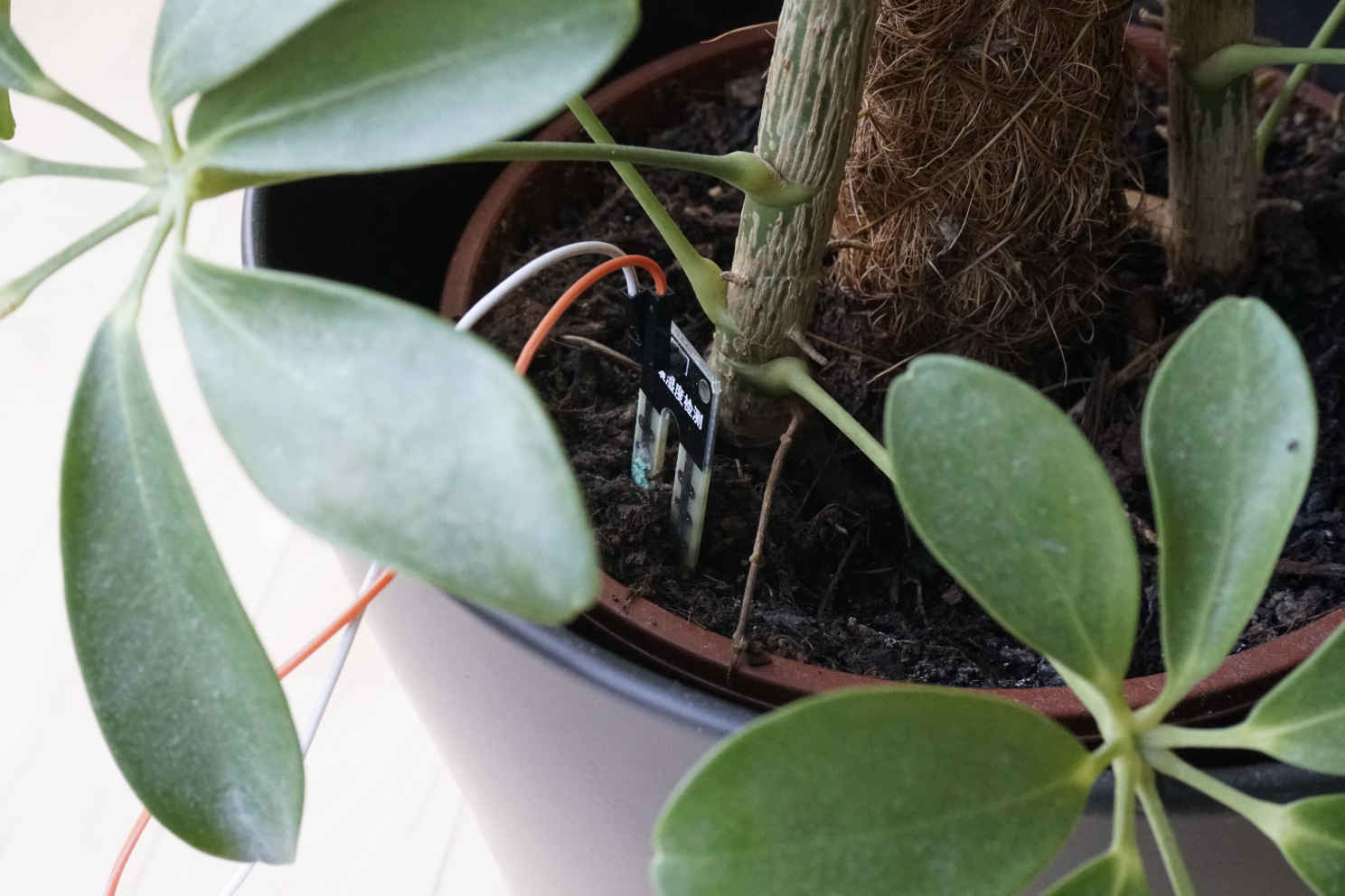
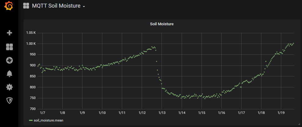
Soil Moisture Sensor Arduino Nano

Soil Moisture Sensor Arduino Pro Mini
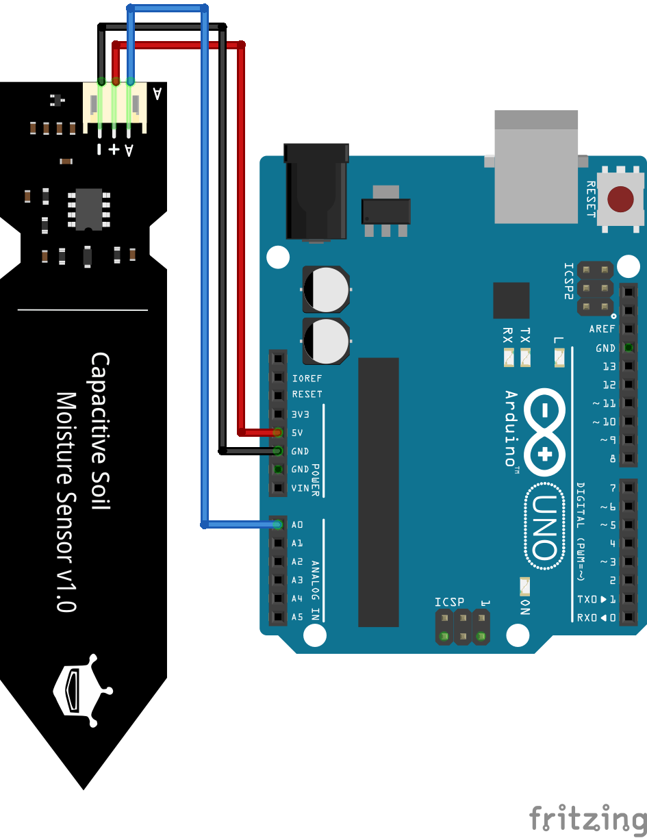
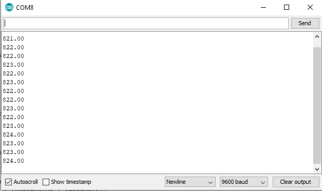
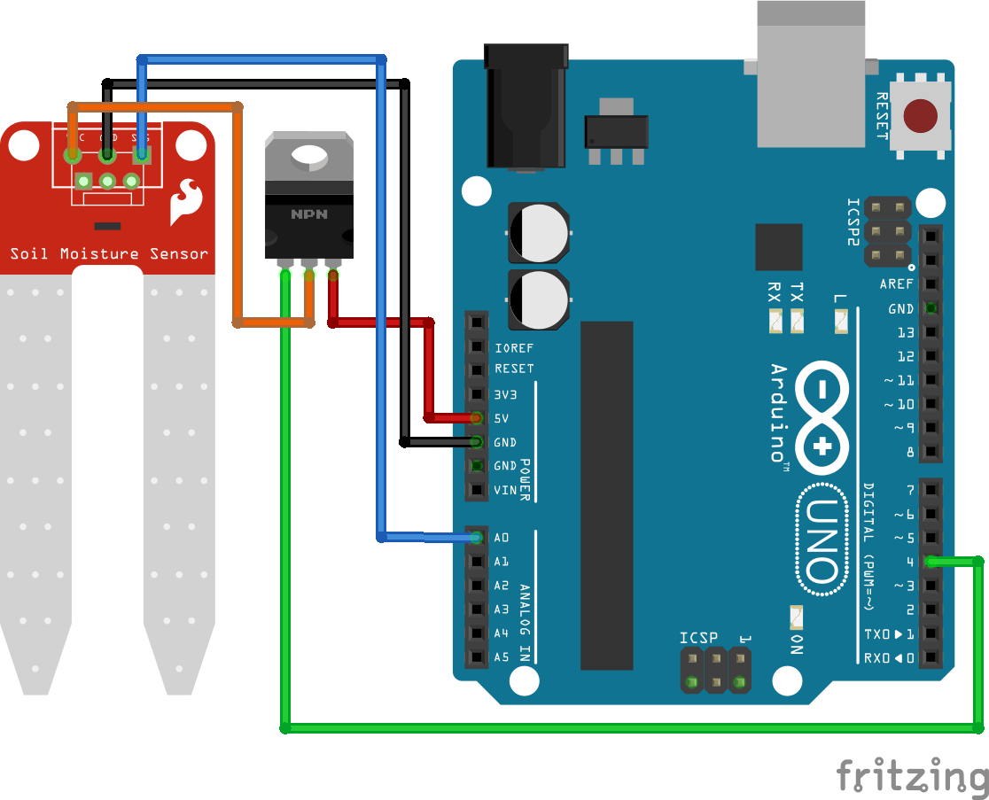
Soil Moisture Sensor Arduino Uno
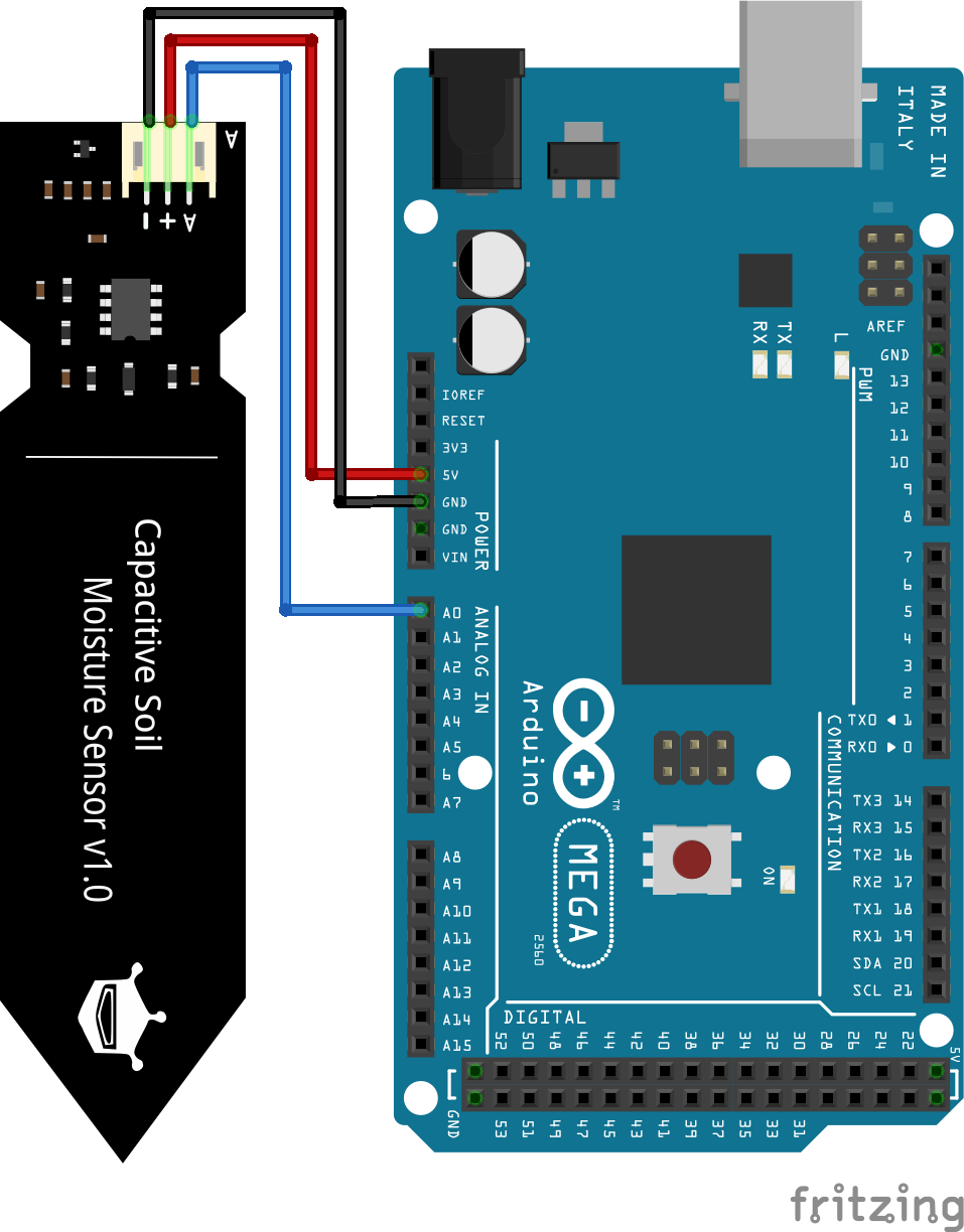
Soil Moisture Sensor Arduino Mega
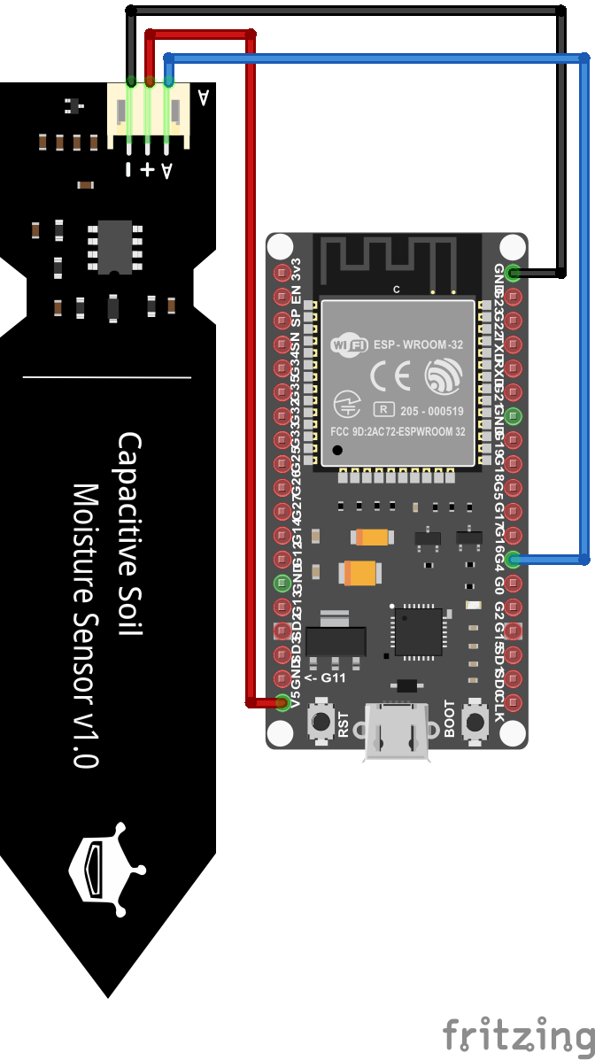
Soil Moisture Sensor ESP32 NodeMCU
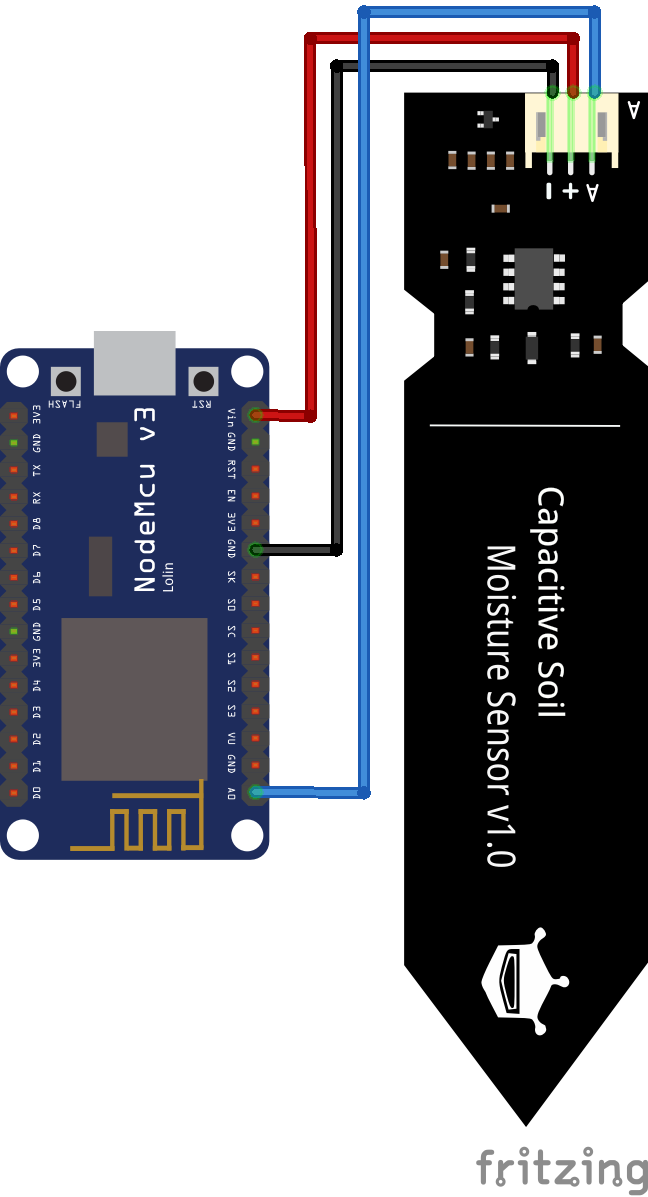
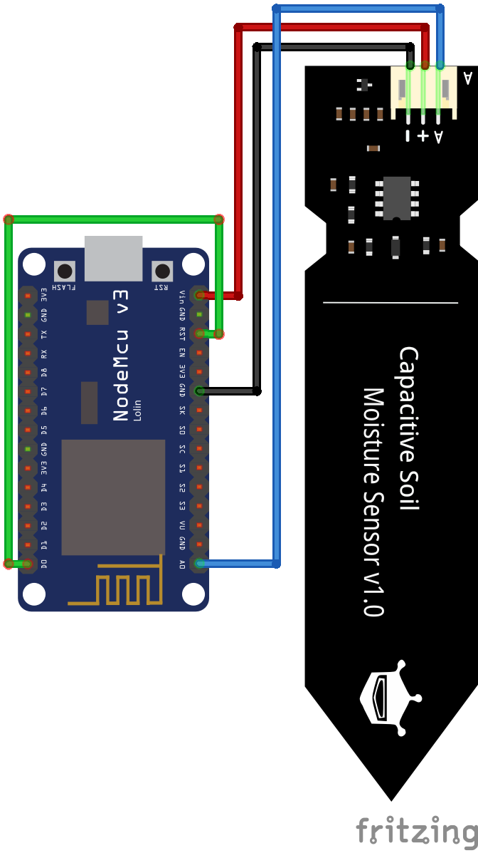
Soil Moisture Sensor ESP8266 NodeMCU
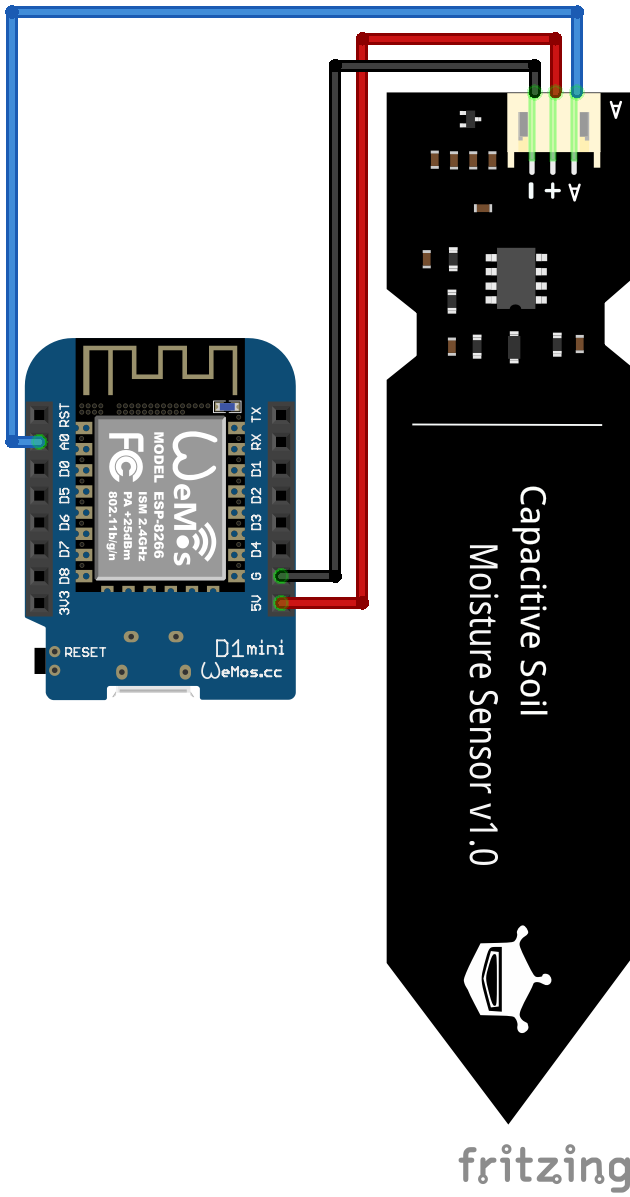
Soil Moisture Sensor ESP8266 WeMos D1 Mini

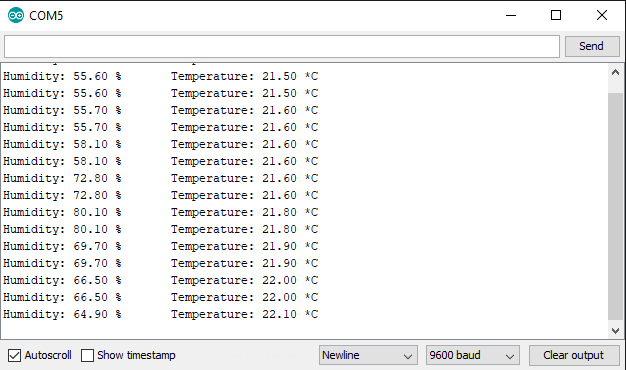
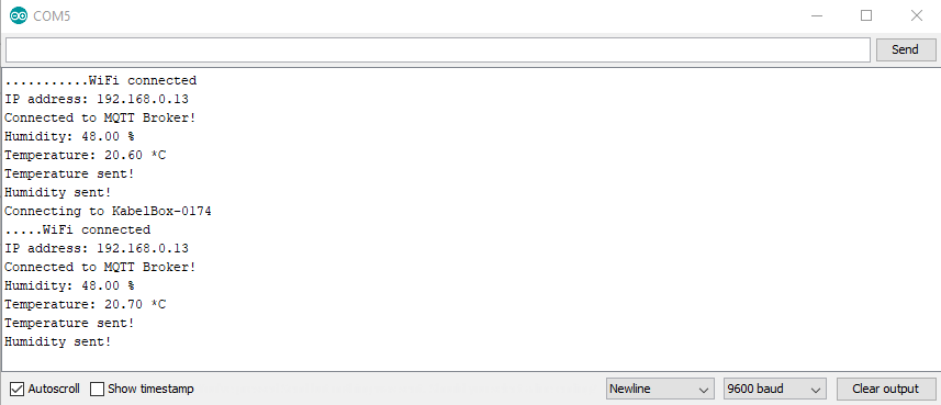
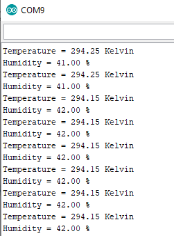
DHT22 Module ESP32 NodeMCU

DHT22 Module ESP8266 NodeMCU
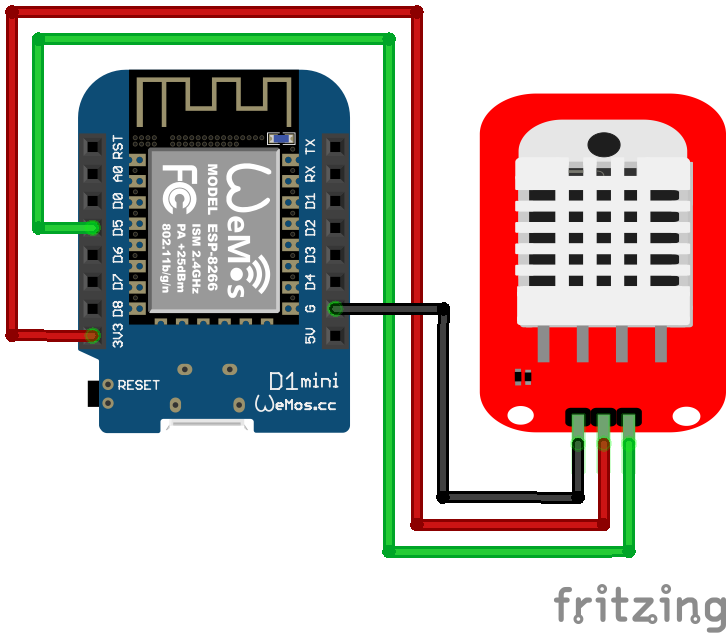
DHT22 Module ESP8266 WeMos D1 Mini