MQ2 Gas Sensor Tutorial for Arduino, ESP8266 and ESP32
In this tutorial I show you how to use the MQ2 gas sensor with your Arduino, ESP8266 or ESP32 microcontroller.
After we dive into the functionality of gas sensors in general, we build a gas alarm that detects smoke and wakes you up with a loud noise.
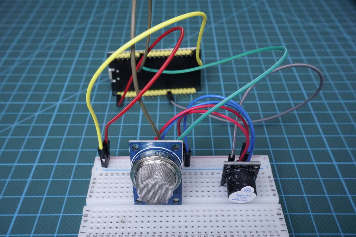
Table of Contents
General functionality of Gas Sensors
First of all we start with the general functionality of gas sensors. Inside the gas sensor is a chemiresistor that changes the resistance based on its sensing material. The following picture helps us to understand this functionality.
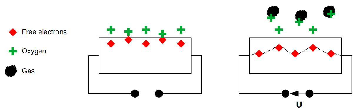
In most cases the sensing material is a tin dioxide (SnO2) material that has free electrons inside. These free electrons are attracted by the oxygen towards the surface of the sensing material (left side of the picture). On the surface, the oxygen is absorbed, due to the heated surface and therefore there are no free electrons in the tin dioxide. The result is: without free electrons there is no electrical current flow.
In an environment of toxic or combustible gases, the gas breaks the connection between the absorbed oxygen and the electrons. (right side of the picture) The released electrons are now free and back in their initial position, where they enable the current flow. How high the current flow is, depends on the amount of free electrons available in the SnO2 that is proportional with the concentration of toxic or combustible gases.
Due to Ohms law a higher current flow results in a higher potential difference, which is measured as output voltage on the analog output of the sensor, using a simple voltage divider network. Therefore the concentrations of gas can be measured.
The type of sensor is defined by the sensing material inside the sensor. Although some of the gas sensors are sensitive to multiple gases, the sensor can not identify which of the gases are in higher concentration.
Overview of Gas Sensors
The following table gives you an overview about the different gas sensors that are available and what gasses they are able to detect. I concentrated on the most used gas sensors, because there are more available then shown in the table.
The MQ2 Gas Sensor Module
In this tutorial I use the MQ2 gas sensor to detect the butane that is emitted by a lighter. The MQ2 gas sensor has an operating voltage of 5V that is also used as heater for the surface of the SnO2. Because it takes some time until the surface is hot, the MQ2 gas sensor has a preheat duration of around 20 seconds.
However the sensor is only suitable to measure a trend of gas concentration and not the exact gas concentration because the relation between ration in voltage change and concentration is nonlinear. If you want to measure the exact concentration, you have to buy a much more precise and costly sensor.
The following picture shows the minimum and maximum concentration of different gases that can be measured with the sensor.
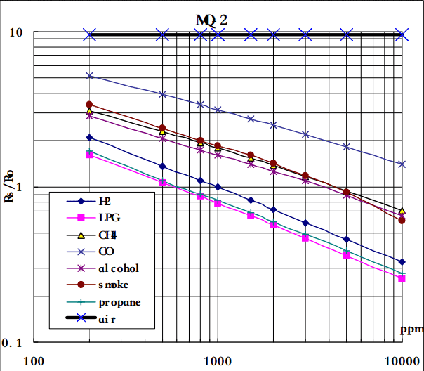
According to the graph, you see that the minimum gas concentration that can be measured is around 100ppm and the maximum around 10000ppm. The unit ppm stands for parts per million and therefore the concentration of gas between 0.01% and 1% can be measured.
Most MQ2 gas sensors are build on a breakout board that has a build in comparator for setting a threshold of gas concentration and provide a digital output to the microcontroller. The comparator compares the analog value with the threshold, that is set by a potentiometer, and changes the digital value from LOW (0) to HIGH (1) if this threshold is exceeded.
The following picture shows the front and the rear side of the MQ2 gas sensor breakout board.
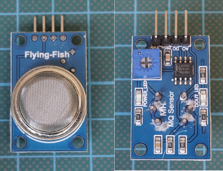
In the right picture you see the 4 pins that we connect to the microcontroller (from the left to the right):
- VCC
- Ground
- Digital Pin
- Analog Pin
Under the pins of the board you see the potentiometer on the left side and the comparator as IC on the board.
Moreover there is a power LED that signals the operation readiness of the MQ2 gas sensor and a second LED labeled DOUT LED that turn on when the digital value changes from LOW to HIGH.
The following table gives you an overview of all components and parts that I used for this tutorial. I get commissions for purchases made through links in this table.
Building a Gas Alarm
Now we want to build a gas alarm with the MQ2 gas sensor, an active buzzer and your favorite Arduino, ESP8266 or EPS32 microcontroller. The following pictures show how to connect the MQ2 gas sensor to different microcontroller boards. I also added an active buzzer to the project that makes a sound if the sensor detects gas in the air. If you are interested in more details about active or passive buzzers, visit the sound tutorial.
Wiring between MQ2 Gas Sensor and Microcontroller
Because the operating voltage of the MQ2 gas sensor is 5V, you have to use the Arduino Pro Mini in the 5V version and not the 3.3V version or any other microcontroller.
If your favorite board is missing, use the comment section below and I will add your board to this article.
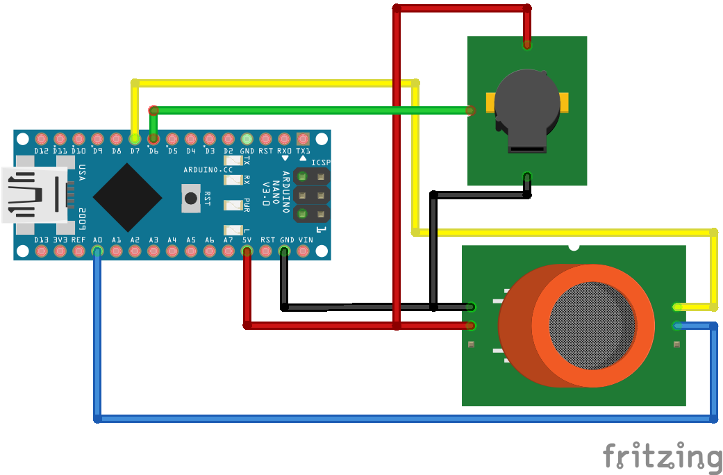
MQ2 Gas Sensor Arduino Nano

MQ2 Gas Sensor Arduino Pro Mini
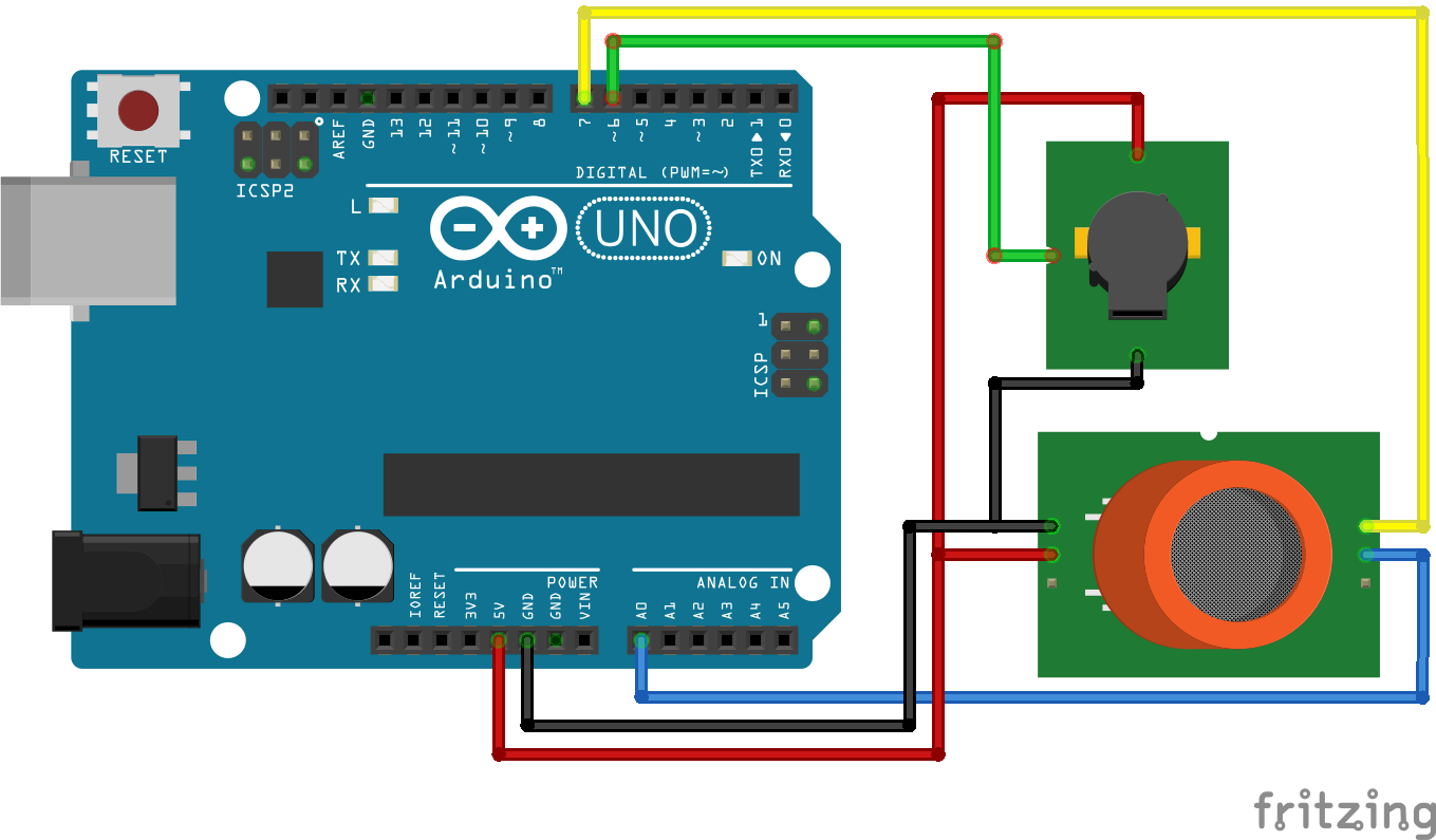
MQ2 Gas Sensor Arduino Uno
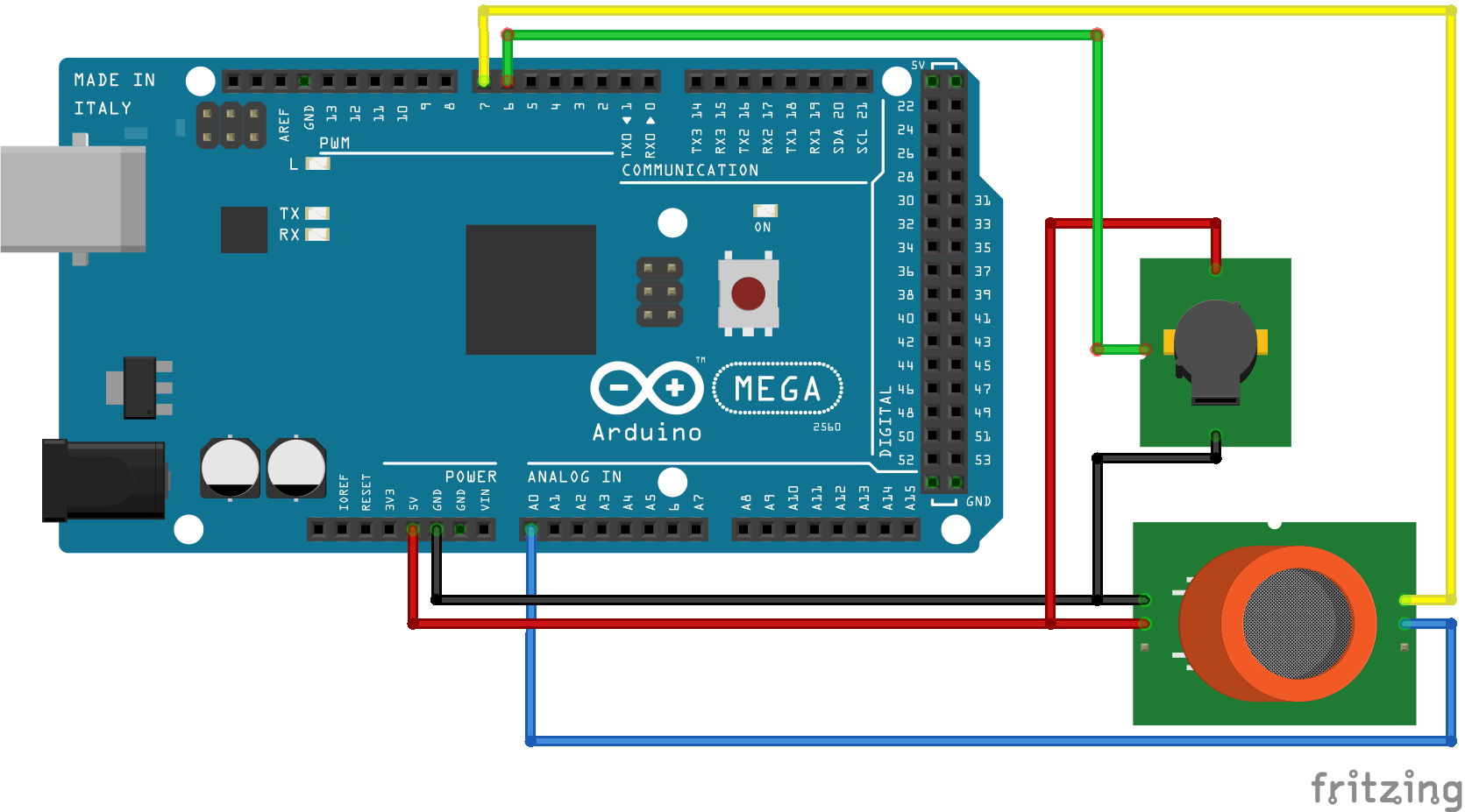
MQ2 Gas Sensor Arduino Mega
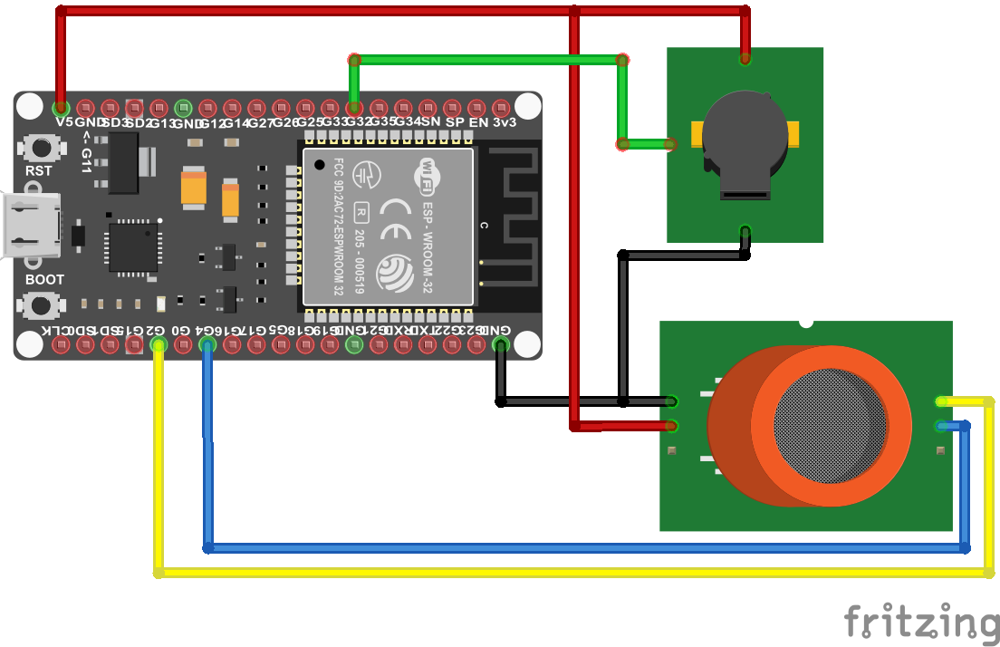
MQ2 Gas Sensor ESP32 NodeMCU
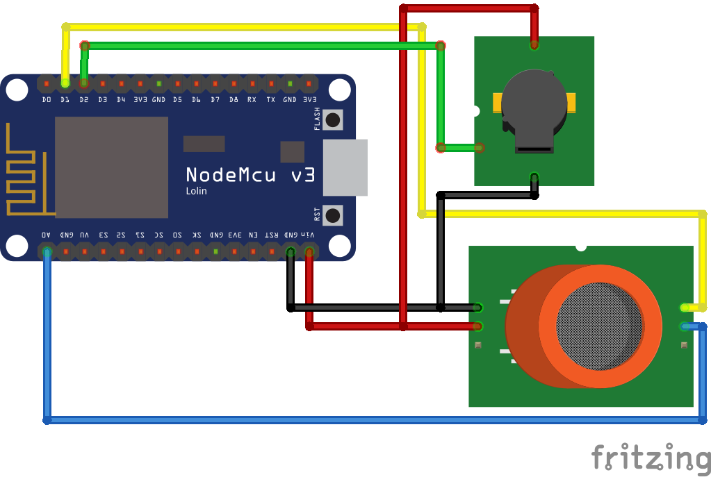
MQ2 Gas Sensor ESP8266 NodeMCU
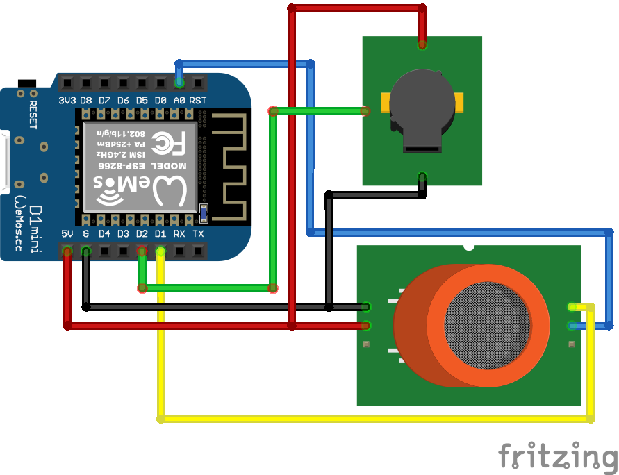
MQ2 Gas Sensor ESP8266 WeMos D1 Mini
From the wiring between the fire sensor and the different Arduino, ESP8266 and ESP32 microcontroller, you see that I use different pins. Therefore we have to take care, that the right pins are used in the program code.
Arduino Code for the Gas Alarm
//int Buzzer = 6;        // used for Arduino
//int Gas_analog = A0;    // used for Arduino
//int Gas_digital = 7;   // used for Arduino

//int Buzzer = D2;        // used for ESP8266
//int Gas_analog = A0;    // used for ESP8266
//int Gas_digital = D1;   // used for ESP8266

int Buzzer = 32;        // used for ESP32
int Gas_analog = 4;    // used for ESP32
int Gas_digital = 2;   // used for ESP32

void setup() {
  Serial.begin(115200);
  pinMode(Buzzer, OUTPUT);
  pinMode(Gas_digital, INPUT);
}

void loop() {
  int gassensorAnalog = analogRead(Gas_analog);
  int gassensorDigital = digitalRead(Gas_digital);

  Serial.print("Gas Sensor: ");
  Serial.print(gassensorAnalog);
  Serial.print("\t");
  Serial.print("Gas Class: ");
  Serial.print(gassensorDigital);
  Serial.print("\t");
  Serial.print("\t");

  if (gassensorAnalog > 1000) {
    Serial.println("Gas");
    digitalWrite (Buzzer, HIGH) ; //send tone
    delay(1000);
    digitalWrite (Buzzer, LOW) ;  //no tone
  }
  else {
    Serial.println("No Gas");
  }
  delay(100);
}
In the first part of the program code we define the pins that connect the MQ2 gas sensor, the active buzzer and the Arduino, ESP8266 or ESP32 microcontroller.
The following table shows what pins I choose for the connection.
Because I added the lines of code for all three microcontrollers, you have to comment and uncomment the first part of the code dependent on your microcontroller.
The ESP32 has a build-in analog to digital converter, so you can use multiple pins as analog input. The pins that you can use as analog pins are described in the ESP32 pinout tutorial.
In the setup function we set the baud rate to 115200 and define the pin modes:
- The microcontroller sends the digital value to the buzzer → Output
- The microcontroller gets the current digital status of the MQ2 gas sensor → Input
In the loop function we read the analog and digital value of the MQ2 gas sensor and save the values in different variables. Now we print the values to the serial output to see the values in the serial monitor of the Arduino IDE. For a better reading we separate each variable with a tabulator.
Now we have to define the threshold when we want to activate the buzzer or not. Therefore we compare the current analog sensor value with a constant, in my case 1000. If the analog sensor is greater than 1000, gas is detected and we set the buzzer active for one second. After this one second we deactivate the active buzzer again.
The following picture shows the output of the serial monitor with the program code in the next section.
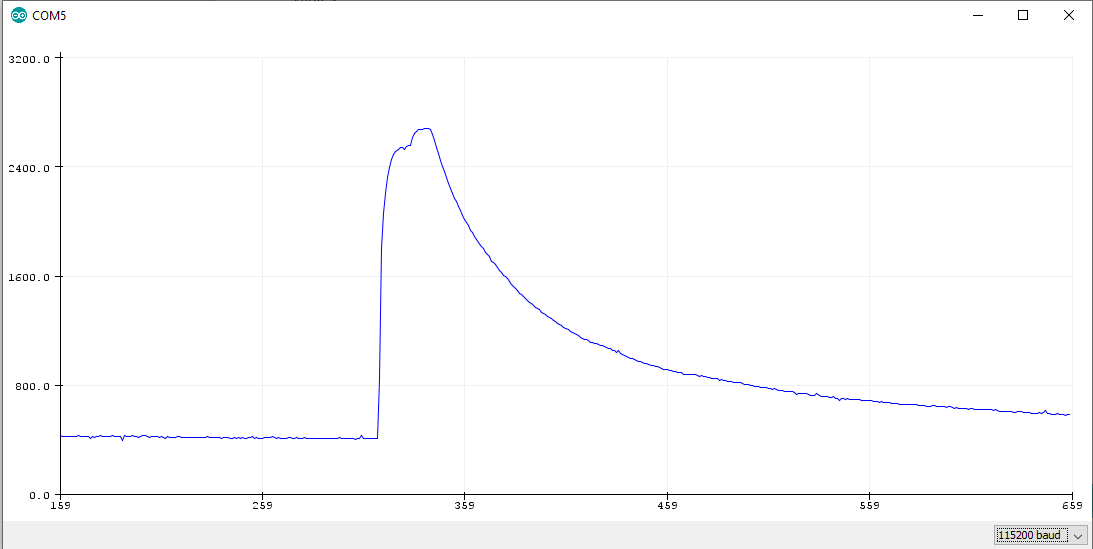
You see clearly, when I activate the cigarette lighter, the analog value spikes above 1000. Also in the following video you see that when the gas sensor detects the gas, the buzzer is activated.
Bonus: Analog value while MQ2 heating
We can also make the preheating visible in the analog signal. The wiring stays the same and you only need the following short program code and open the serial plotter of the Arduino IDE.
//int Gas_analog = A0;    // used for Arduino
//int Gas_analog = A0;    // used for ESP8266
int Gas_analog = 4;    // used for ESP32

void setup() {
  Serial.begin(115200);
}

void loop() {
  int gassensorAnalog = analogRead(Gas_analog);
  Serial.println(gassensorAnalog);
  delay(100);
}
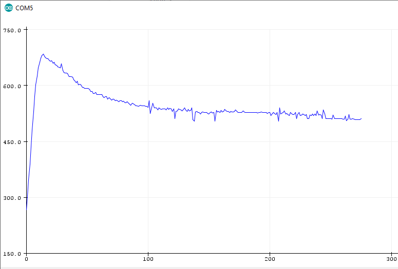
The x-axes shows the time in 1 seconds. During the preheating the analog sensor value spikes to around 700 in the first 10 seconds and then stabilizes around 500 after 200 seconds.
I hope you enjoyed reading the tutorial about the MQ2 gas sensor. You can also add a fire sensor to the gas alarm to detect an active fire. In the fire sensor tutorial you learn how to add the sensor to your project.
If you have any questions regarding this article, use the following comment section to ask your questions. I will answer them as soon as possible.
Leave A Comment