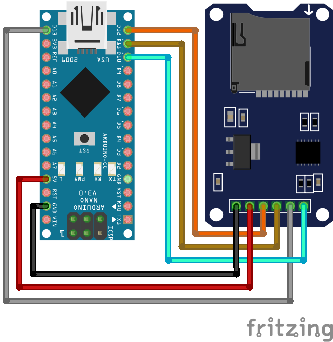
SD Card Module Arduino Nano
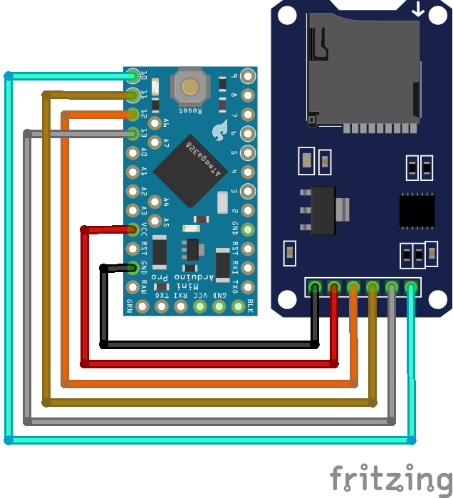
SD Card Module Arduino Pro Mini
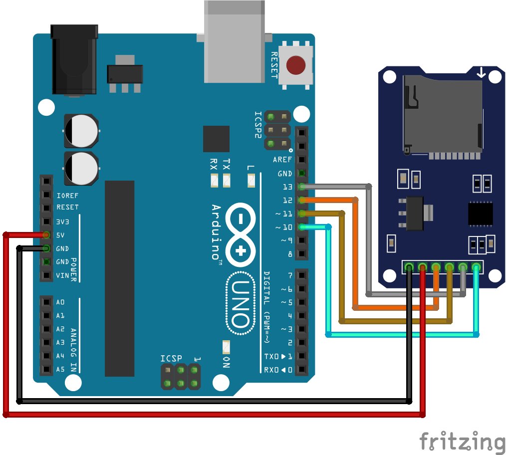
SD Card Module Arduino Uno
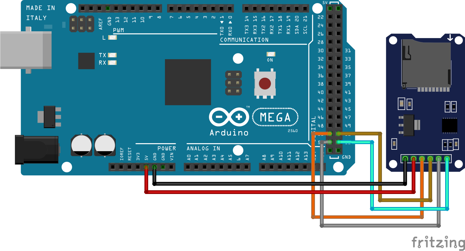
SD Card Module Arduino Mega
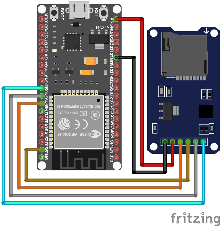
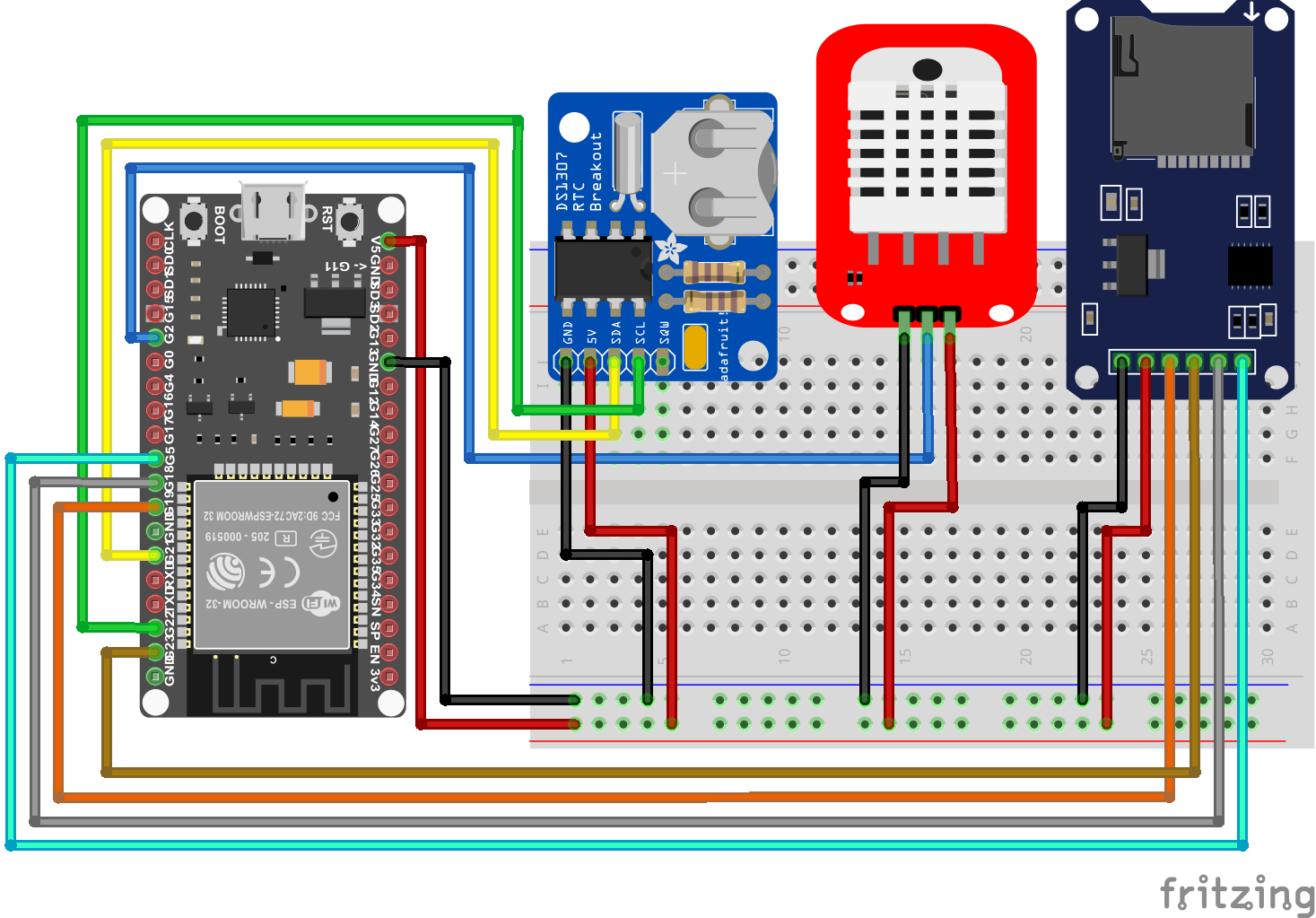
SD Card Module ESP32 NodeMCU
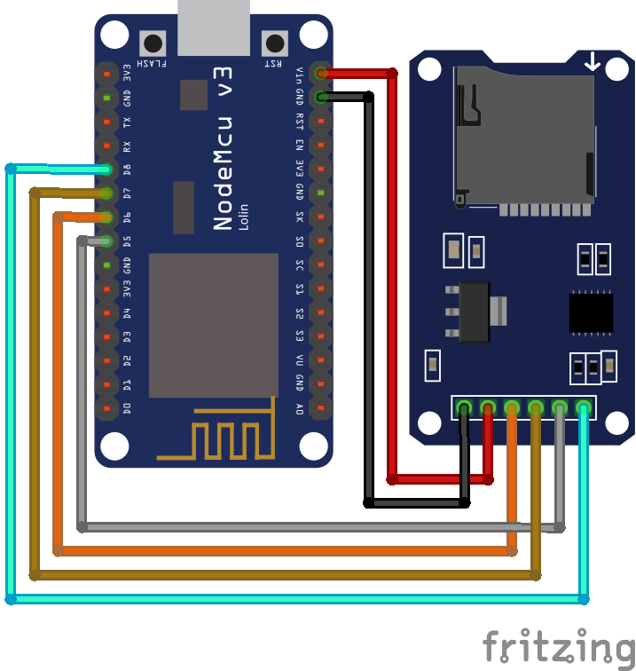
SD Card Module ESP8266 NodeMCU
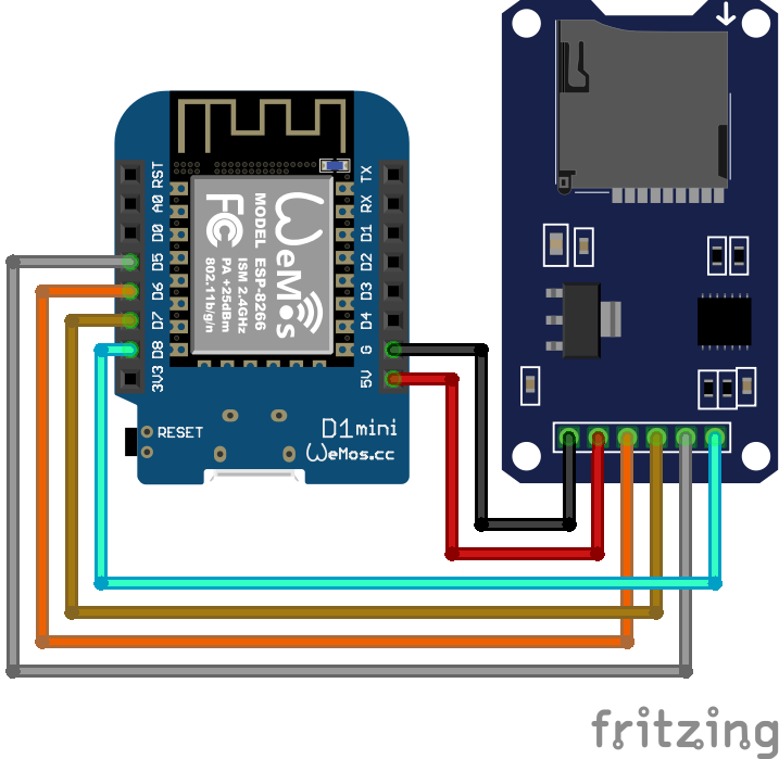
SD Card Module ESP8266 WeMos D1 Mini

Temperaturelogger RTC Arduino Nano
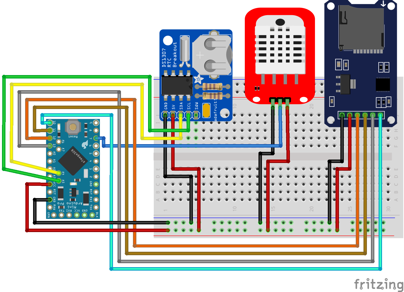
Temperaturelogger RTC Arduino Pro Mini
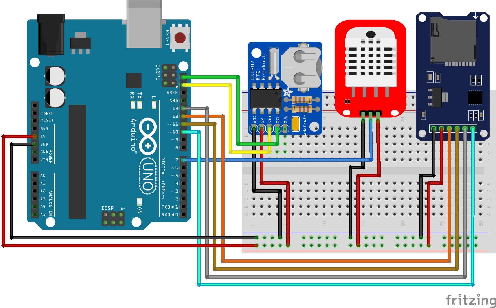
Temperaturelogger RTC Arduino Uno
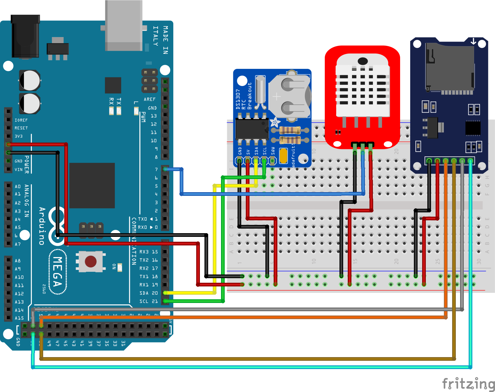
Temperaturelogger RTC Arduino Mega
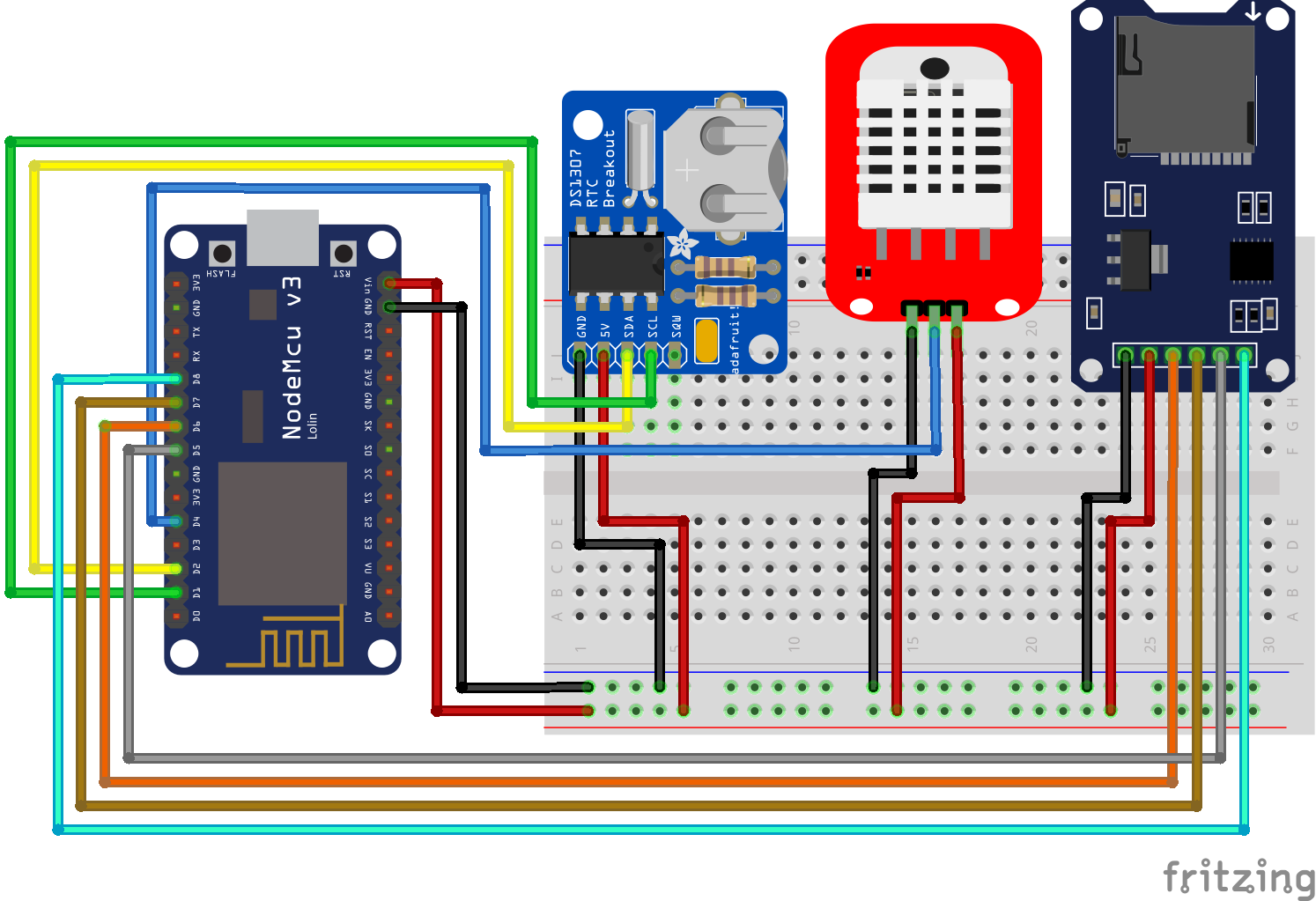
Temperaturelogger RTC ESP8266 NodeMCU

Temperaturelogger RTC ESP8266 WeMos D1 Mini
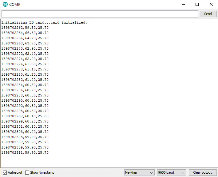
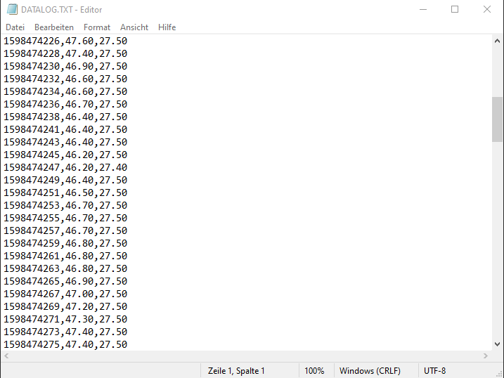
Interesting samples but not enough.Writing time in Unix system without conversion is a misconception. Where do we set the current time for Rtc?
Anyway thanks!
Hi Ron, maybe I do not get your point but the Unix timestamp is for everybody on the world the same. I only store data on the SD card to make some data analysis or to visualize the data. Therefore I can easily convert the unix timestamp during the data preprocessing.
Hi there! Great project and clear explanations. I’ve read through it and really have just one question. Is it possible to use the stored data on the SD card and send that stored data through the ESP8266 NodeMCU to a Google Spreadsheet? Right now I have a working Arduino script linked to a Google Spreadsheet so I can store my data there, but I want to store data while I’m driving in my car. When I get back home and park the car in my garage where there is wifi available I want the ESP8266 to send the logged data that is stored on the SD card. Is this possible through the code that you created? And if not, would you know how to do that?
Hi Mike,
there is a tutorial on hackster where you can find a tutorial: https://www.hackster.io/thatiotguy/sensor-data-upload-to-google-sheets-through-nodemcu-632358
Greetings! Thx for your tutorial! I’m attempting to write an ESP32 app that reads text files that I create on my laptop. I loaded the example included in the core ESP32 Arduino UI, and it operates (using the connection you describe here) and it runs to completion, creating, reading, writing and deleting files without error. I then created .txt files with Notepad, transferred them to the uSD card. The example code reads the directory, recognizes the files I created, but fails to read the contents of the file (with the error msg sent to the serial monitor). I tried creating .txt files in Notepad with each of the file formats available in Notepad, haha; UTF8; UTF16; ANSI, etc. The ESP32 recognizes the files but can’t read them. I was wondering if you had any insight as to what I am doing incorrectly? I’ve been scanning the internet but have yet to turn up an explanation of the file format used….. (Ultimately, I hope to create data matrices in Google Sheets, and export rows/columns of data to be read by the ESP32, so for the heck of it, I exported a file out of Sheets as a .csv (renaming it to a .txt) and Notepad could open it; the ESP32 could see the file in the directory but not open it). Thanks so much for your website and your contributions!
Hi there ! Your explainations are great for a newbie like me. I would like to setup a temperature controller (max31855) for a kiln incl. this data logger. How do I have to implement the max31855 in the sketch ?