Arduino
ESP8266 and ESP32
Arduino
ESP8266 and ESP32
Arduino Nano
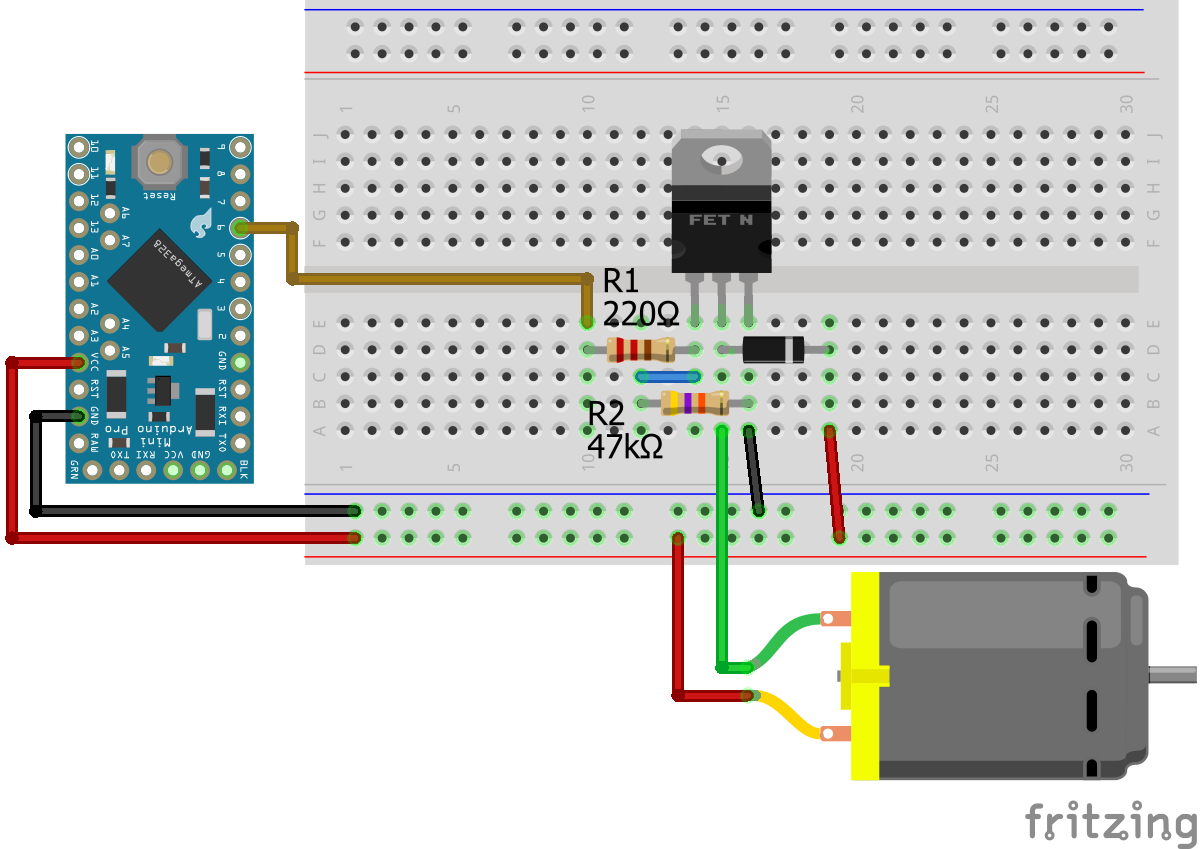
Arduino Pro Mini
Arduino Uno
Arduino Mega
Arduino Nano
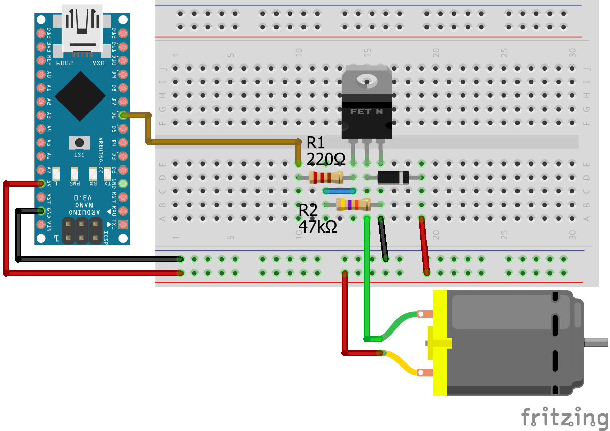
For more information about the Arduino Nano, visit the Arduino Nano Tutorial.
Arduino Pro Mini
Arduino Uno
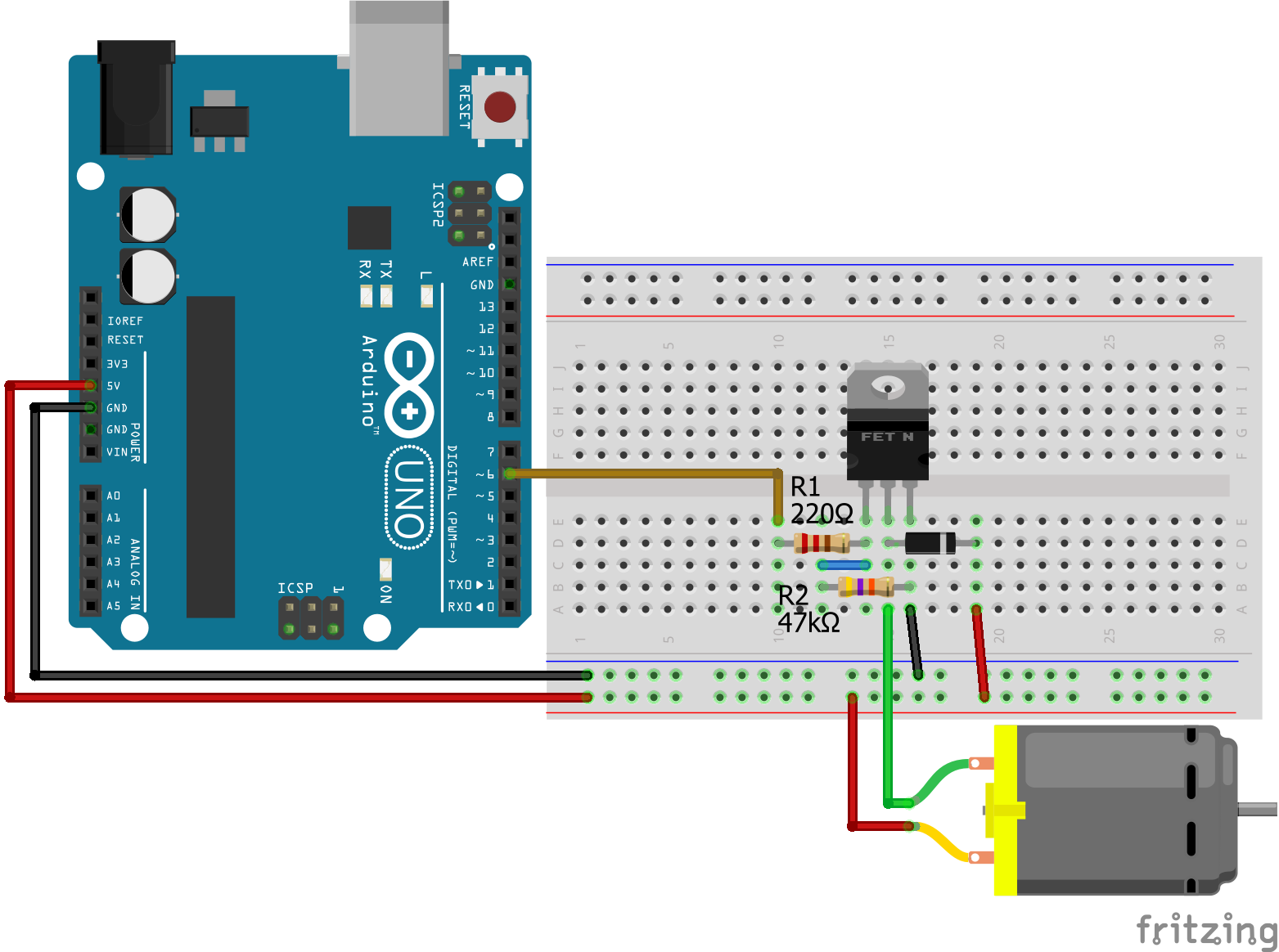
For more information about the Arduino Uno, visit the Arduino Uno Tutorial.
Arduino Mega
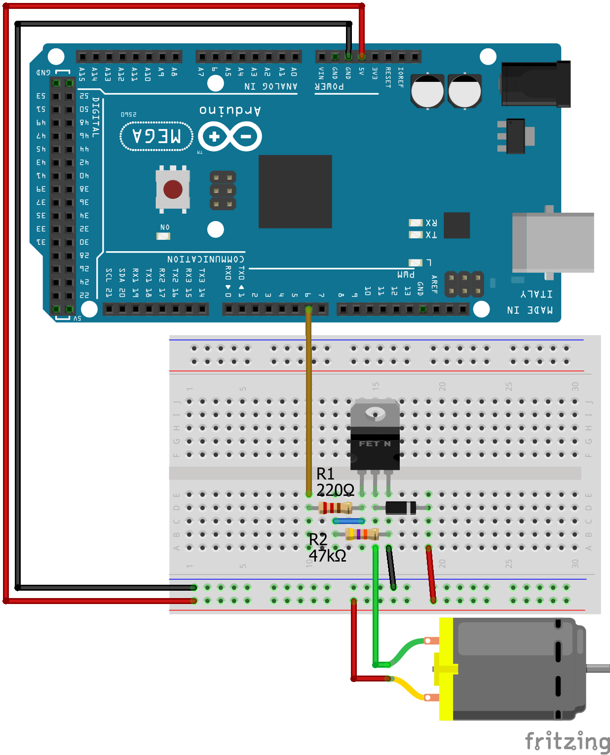
For more information about the Arduino Mega, visit the Arduino Mega Tutorial.
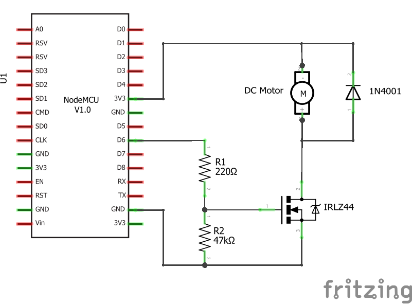
ESP8266 NodeMCU
ESP8266 WeMos D1 Mini
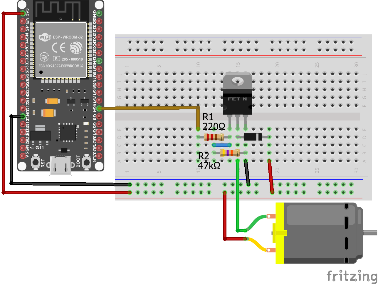
ESP32 ESP-WROOM-32
ESP8266 NodeMCU
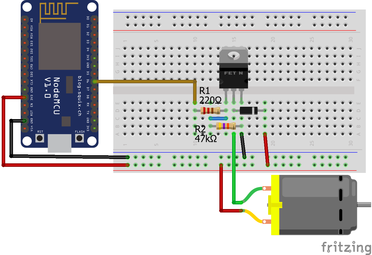
For more information about the ESP8266, visit the ESP8266 NodeMCU Tutorial.
ESP8266 WeMos D1 Mini
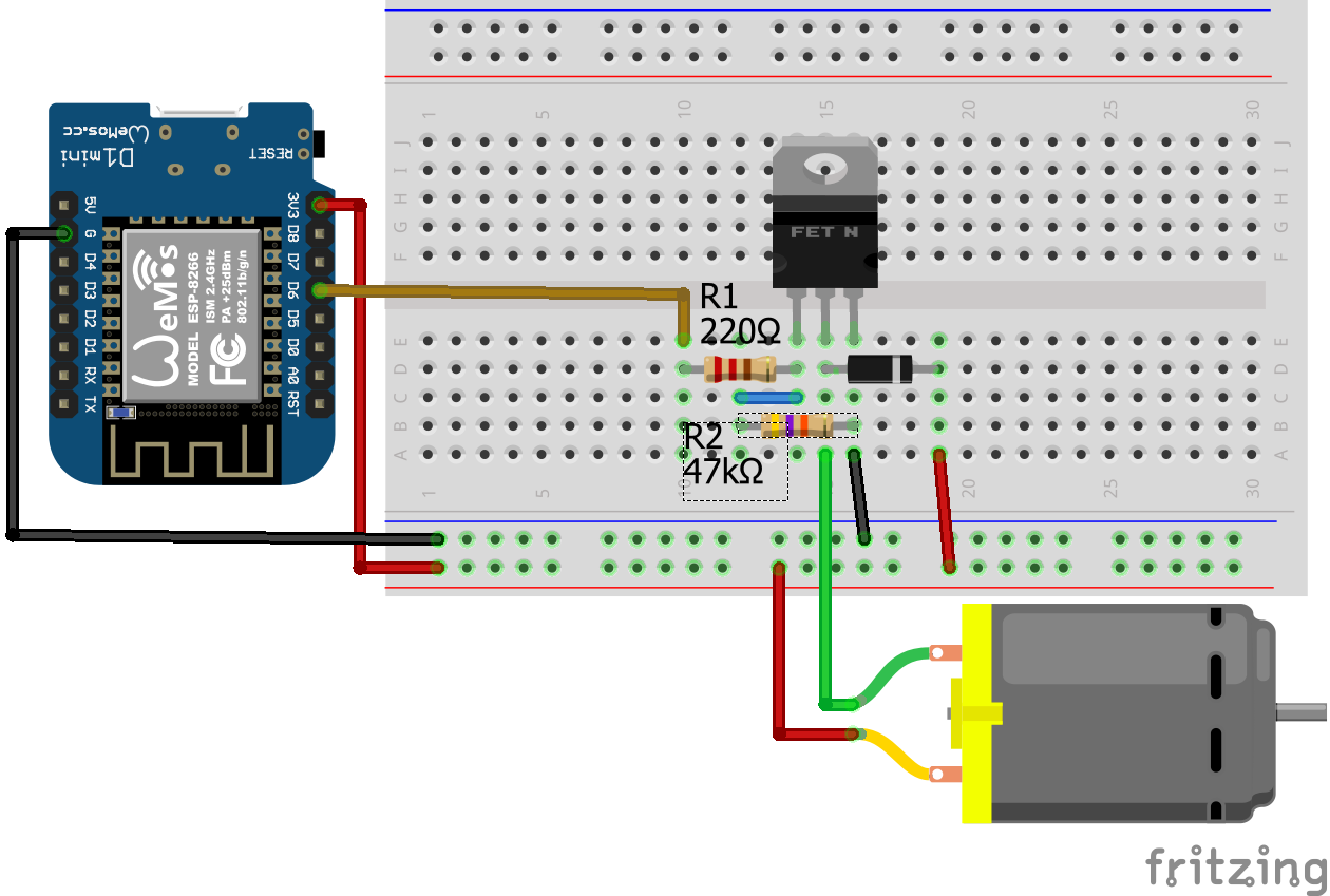
For more information about the ESP8266 WeMos D1 Mini, visit the ESP8266 WeMos D1 Mini Tutorial.
ESP32 ESP-WROOM-32
Arduino: R2=10k
Arduino: R2=22k
Arduino: R2=47k
Arduino no R2
ESP8266: R2=10k
ESP8266: R2=22k
ESP8266: R2=47k
ESP8266 no R2
Arduino: R2=10k
Max voltage is 1.512V

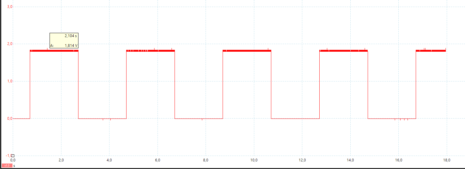
Arduino: R2=22k
Max voltage is 1.814V
Arduino: R2=47k
Max voltage is 2.695V

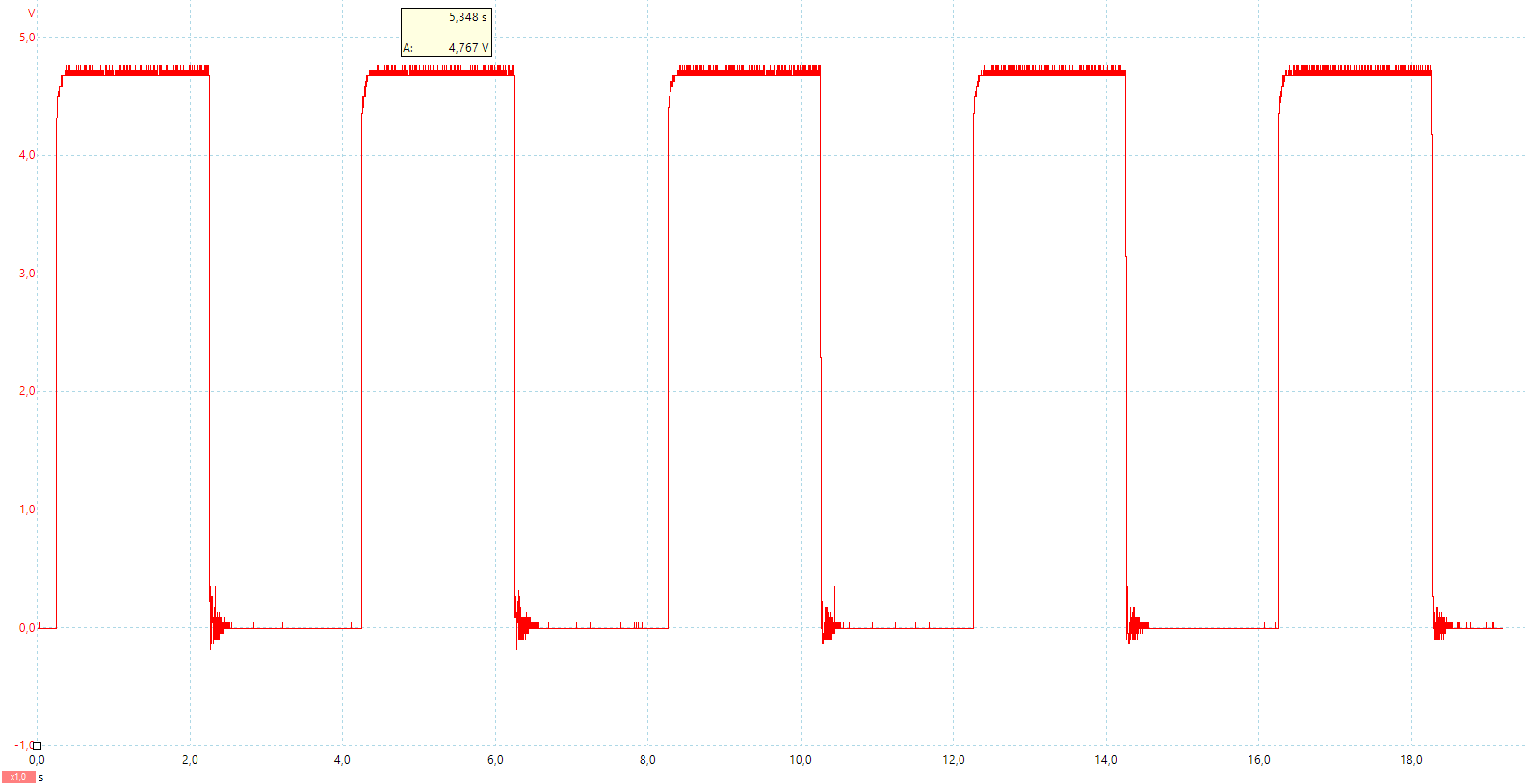
Arduino no R2
Max voltage is 4.767V
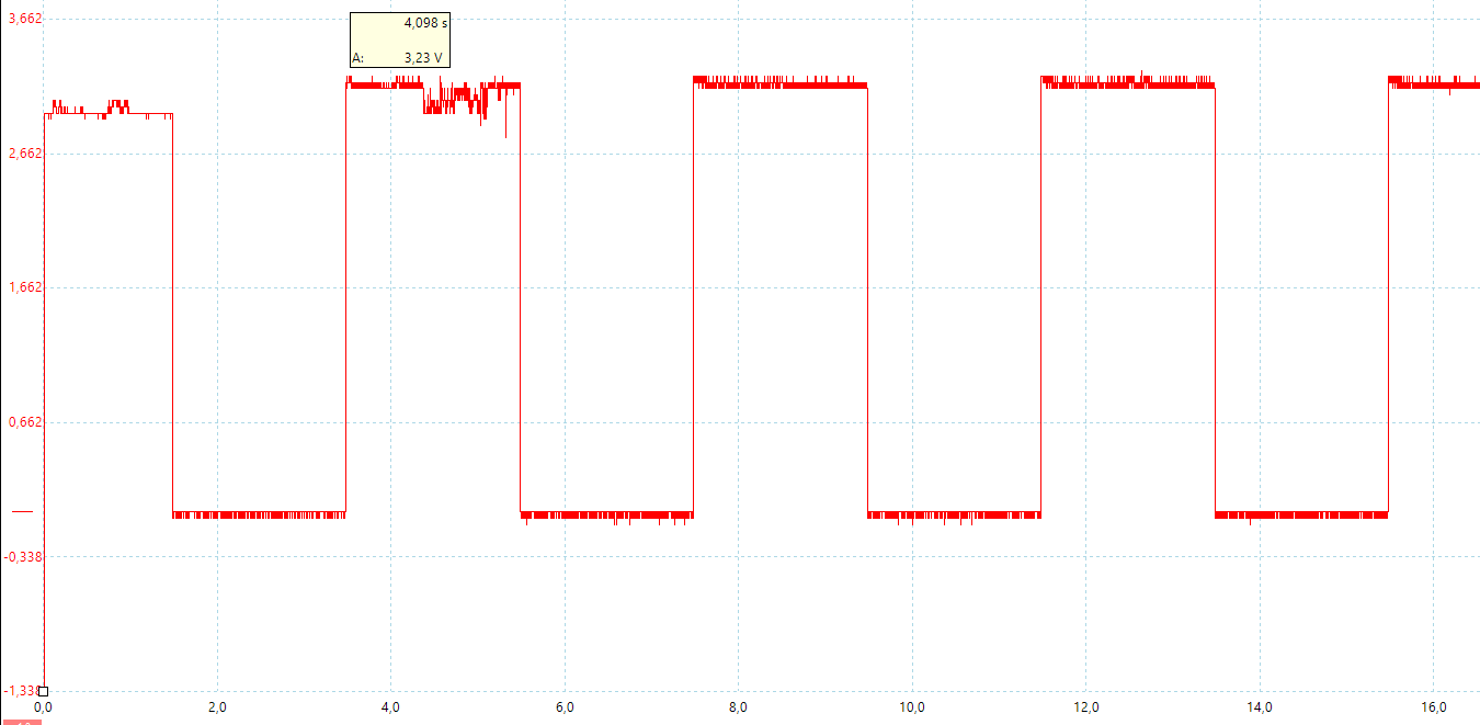
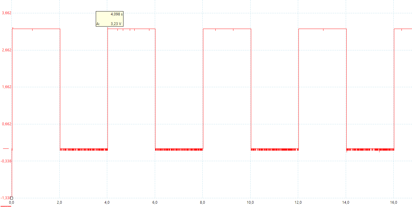
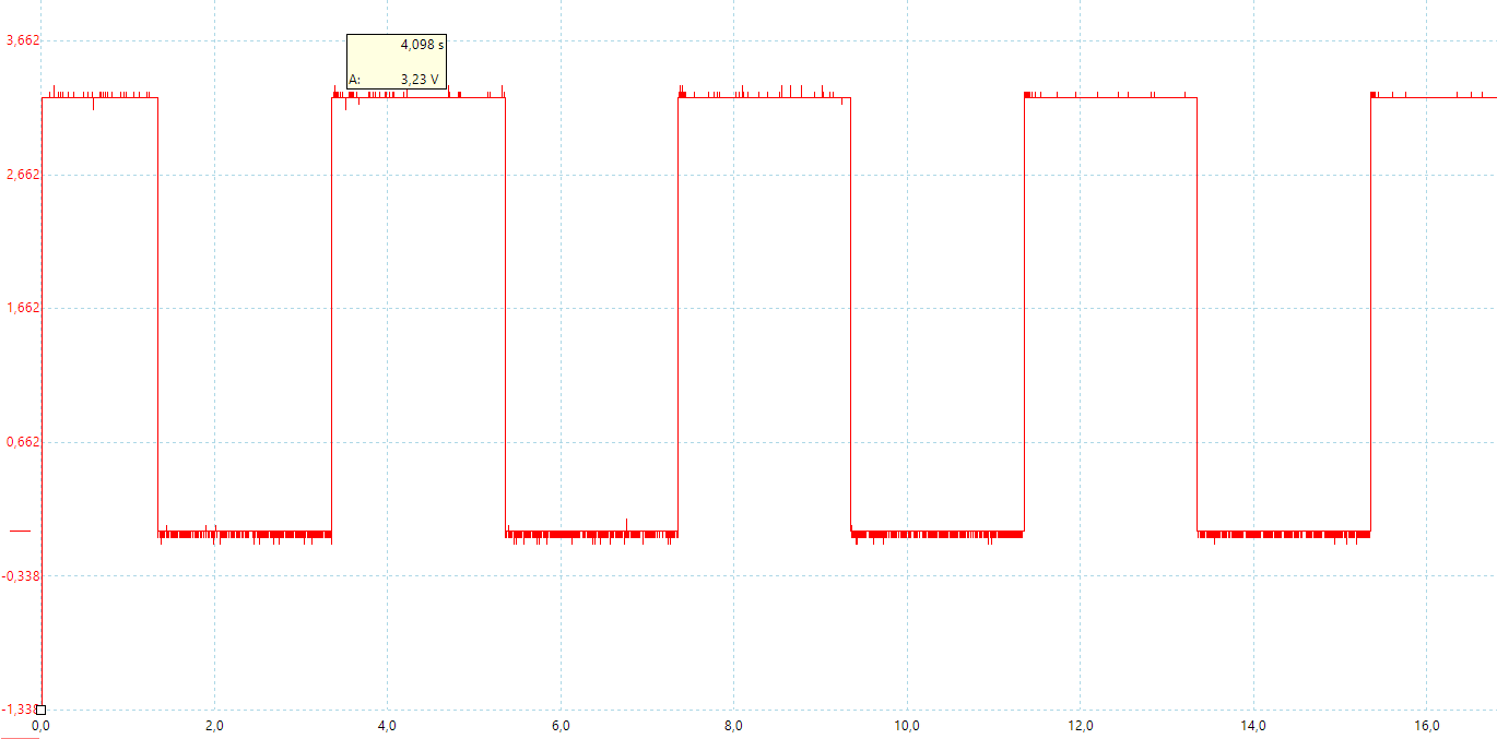
ESP8266: R2=10k
Max voltage is 3.23V
ESP8266: R2=22k
Max voltage is 3.23V
ESP8266: R2=47k
Max voltage is 3.23V
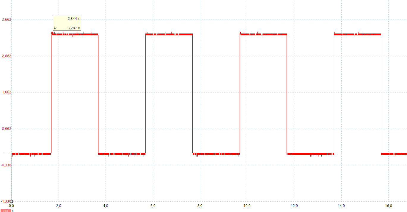
ESP8266 no R2
Max voltage is 3.287V

By loading the video, you agree to YouTube's privacy policy.
Learn more

Very good content, I followed the steps and wrote some programs myself.
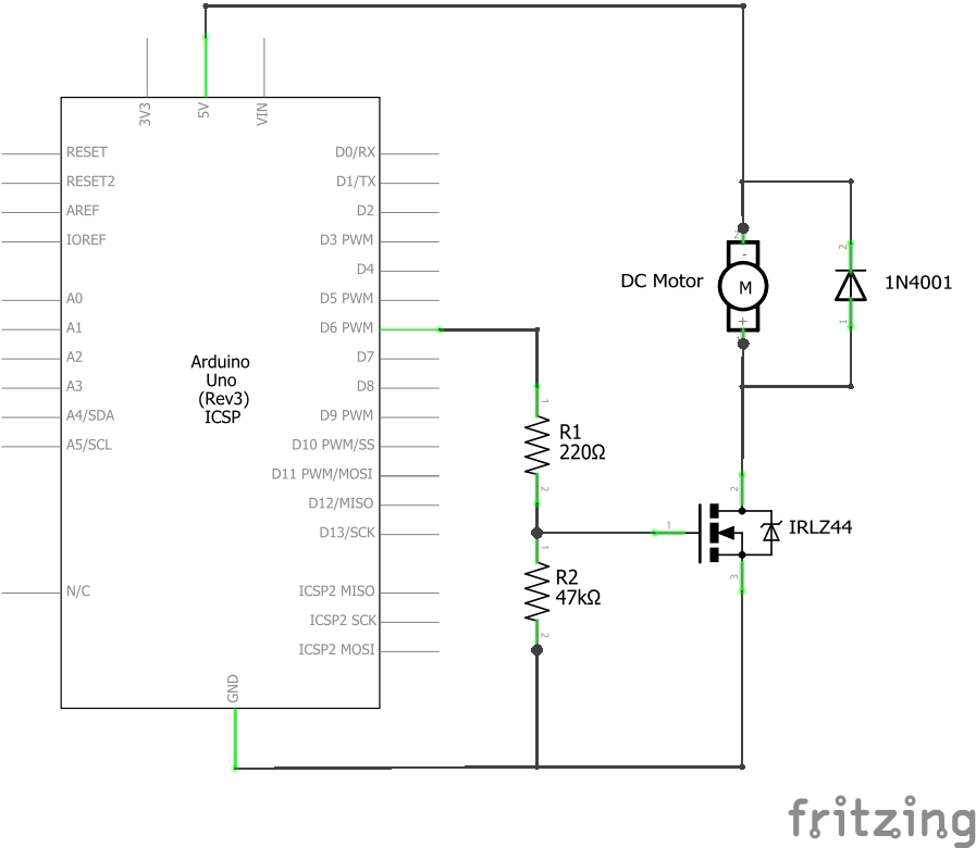
Thanks – great article 🙂 Just FYI 0 the links are to the IRF (not IRL).