Arduino Nano Tutorial [Pinout]
In this tutorial you learn everything you have to know about the Arduino Nano:
- Technical datasheet
- What is the pinout of the Nano?
- What is the best power supply for this microcontroller?
- Advantages and Disadvantages of the Arduino Nano.
- Compare the Nano to other Arduino and ESP8266 based microcontroller.
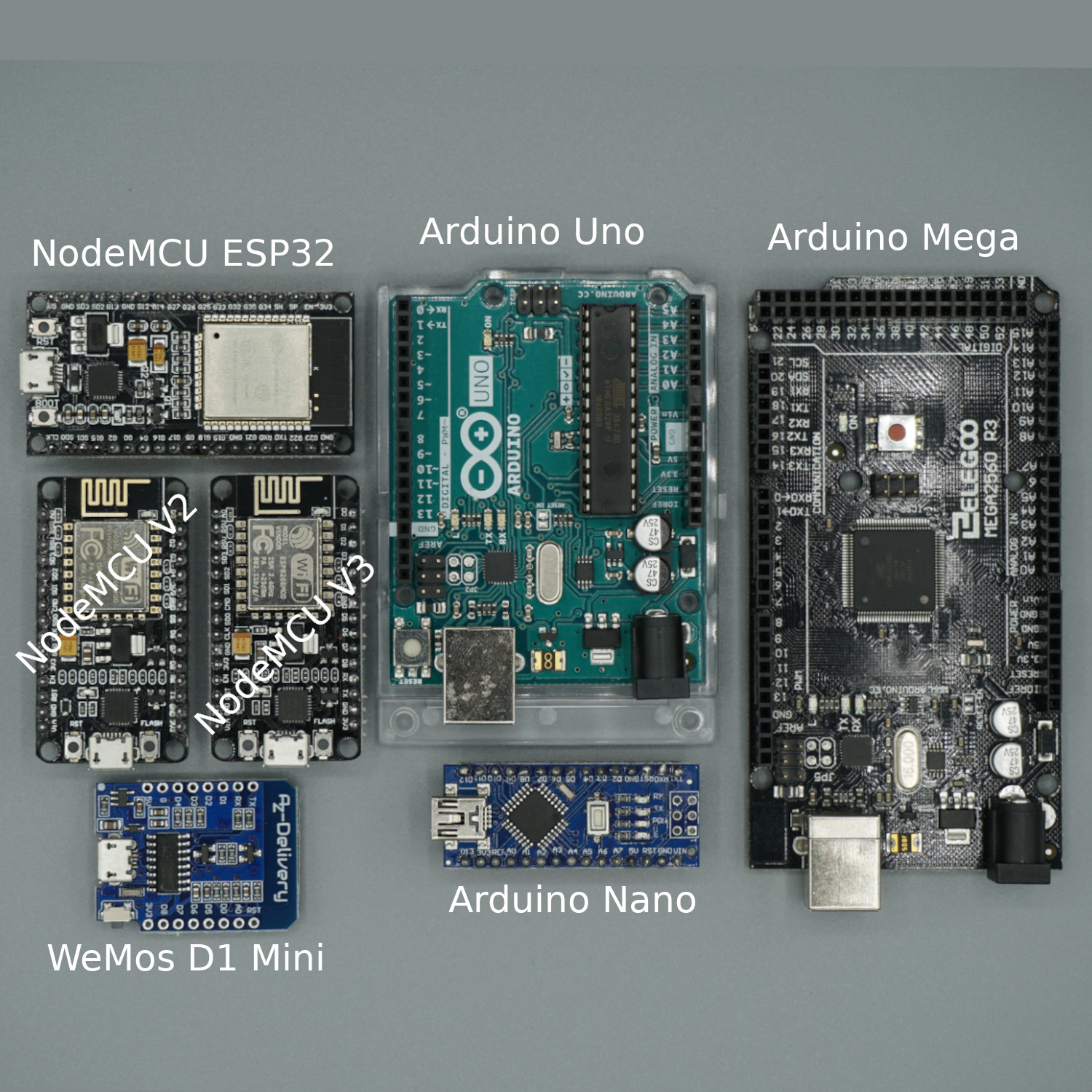
Table of Contents
The Arduino Nano is a microcontroller board, based on the ATmega328P microcontroller by Atmel. The Atmega328 comes with built-in bootloader, which makes it very easy to flash the board with your code. Like all Arduino boards, you can program the software running on the board using a language derived from C and C++. The easiest development environment is the Arduino IDE. The Nano is the smallest board of the Arduino boards but has nearly the same datasheet like the Arduino Uno. Only the power jack is missing and instead of a standard USB port the Nano has a Mini-B USB plug.
The following table contains the datasheet of the Arduino Nano R3 microcontroller board:
| Arduino NANO 3 | |
| Microcontroller | ATmega328p |
| Operating Voltage | 5 V |
| Power supply | 7 V – 12 V |
| Current consumption | 19 mA – 180 mA |
| Current consumption Deep Sleep | 23 µA (with special settings) |
| Digital I/O Pins | 14 |
| Digital I/O Pins with PWM | 6 |
| Analog Input Pins | 8 |
| SPI/I2C/I2S/UART | 1/1/1/1 |
| DC Current per I/O Pin | 40 mA |
| DC Current for 3.3V Pin | 50 mA |
| Flash Memory | 32 KB |
| SRAM | 2 KB |
| EEPROM | 1024 bytes |
| Clock Speed | 16 MHz |
| Length | 45 mm |
| Width | 18 mm |
| WIFI | no |
| Bluetooth | no |
| Touch sensor | no |
| CAN | no |
| Ethernet MAC Interface | no |
| Temperature Sensor | no |
| Hall effect sensor | no |
| Power jack | no |
| USB connection | yes |
| Price | $22 |
Do you want to compare the datasheet of different microcontroller boards like Arduino Uno, Arduino Mega, ESP8266 Node MCU and WeMos D1 Mini? Follow this Link for the comparison.
If you do not already have an Arduino Nano, you can buy one from the following links. I get commissions for purchases made through links in this table.
| Arduino Nano | Amazon | Banggood | AliExpress |
Arduino Nano R3 Pinout
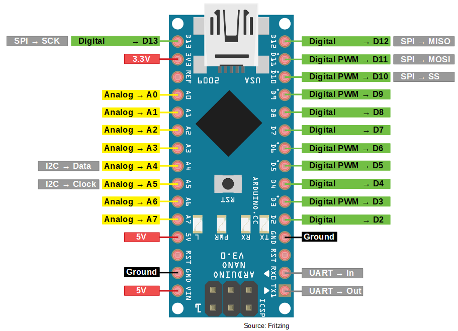
The Arduino Nano is the smallest microcontroller in the Arduino family and has therefore the lowest number of pins and connections. But in my opinion the Nano is very suitable for projects where you do not need a wireless connection.
The Nano has one 3.3V and two 5V power pins of which one is the VIN pin. With the VIN pin you can supply the Arduino Nano with a voltage between 7V-12V to run the microcontroller on battery for example. All three power pins provide a maximum currency of 50 mA. You can close the circuit with two ground pins.
The microcontroller has 8 analog pins with a 10-bit analog-to-digital converter (ADC). The ADC converts the input voltage to a signal between 0 and 1023. There is also the possibility to use the analog pins as output with the function digitalWrite(Ax).
There are in total 14 digital I/O pins which can be used with a maximum currency of 40 mA if you are not using the serial ports RX0 (UART -> In) and RX1 (UART -> Out) and do not use the Serial.begin() function in your Arduino script. If you use the serial ports, then you have in total 12 digital pins (D2…D13) that can be used like you see in the pinout picture. If you want to create a PWM signal for example to control the speed of a motor, there are 6 of the 13 digital pins, which are PWM ready.
You can use pin 2 and 3 as interrupts if you want to monitor an input during the runtime of the whole Arduino script.
The typical communication standards (SPI, I2C and UART) are also available on the Arduino Nano.
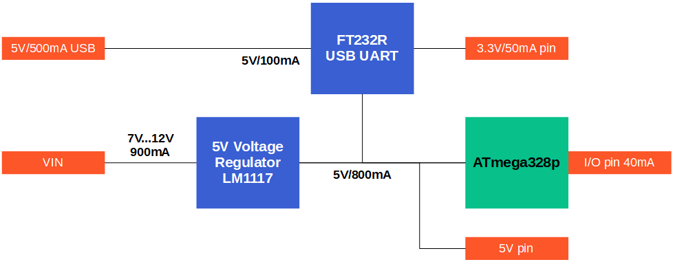
Arduino Nano R3 Power Supply
The Arduino Nano board has different voltage levels, that we have to know before we can dive into the possibilities to supply power to the microcontroller. The following picture shows a schematic of the voltage levels on the Arduino Nano as well as the voltage levels and the maximum currents defined by the components.
The main microprocessor for the Arduino Nano 3 is the ATmega328p.
Microcontroller | Minimum Voltage | Typical Voltage | Maximum Voltage |
ATmega328p | 2.7V | 5V | 6V |
The ATmega328p has an operation voltage of 5V, a minimum voltage of 2.7V and a maximum voltage of 6V. Therefore the two voltage regulators have an output voltage of 5V equal to the operation voltage of the microprocessor.
Arduino Nano Voltage Regulators
The following table shows the voltage specifications of the two onboard voltage regulators.
Voltage Regulator | Output Voltage | Maximum Input Voltage | Maximum Output Current |
LM1117IMPX-5.0 | 5V | 20V | 800mA |
FT232R USB UART | 3.3V | 5.25V | 100mA |
The FT232R USB UART is connected to the USB port of the Arduino Nano that supports the board with 5V and a maximum current of 500mA but it is recommended to only draw a current of 100mA if the microcontroller is powered via USB. The 3.3V pin is also powered from the FT232R voltage regulator that supports up to 50mA.
The second voltage regulator, the LM1117 supports input voltages between 7V and 12V with a maximum current of 900mA. In the data sheet you find a maximum voltage of 20V but this voltage is not recommended for a longer duration because the voltage regulator has no head sink.
The 5V pin of the Arduino Nano is directly connected to the 5V voltage regulator and supports a maximum current that is defined by the difference of the current provided by the voltage regulator and the current from the ATmega328p.
Maximum Current for I/O Pins
Each I/O pin supports a maximum current of 40mA but it is not possible to draw 40mA current over each pin because the maximum allowed current load of the port registers must be considered.
The digital and analog pins of the ATmega328p are connected to different port registers and each port register supports a maximum allowed current that depends on if the register is used as source or as sink. The following table shows which pin is assigned to which port register and also the maximum current.
Pins | D0…D4 | D5…D7 | D8…D13 | A |
Port Register | D0…D4 | D5…D7 | B0…B5 | C0…C5 |
Max Current Source 150mA | ||||
Max Current Sink 100mA |
There are in total 3 port registers: D, B, C. All digital pins D0…D13 are assigned to register D and B. For the maximum current, port register D is separated. All analog pins belong to the port register C.
The maximum current, if the pins are a current source, is 150mA. The sum of all pins in the colored port register should not exceed 150mA:
- Current source of port register D0…D4 + C0…C5 < 150mA
- Current source of port register D5…D7 + B0…B5 < 150mA
If the I/O pin is a current sink, the maximum current is 100mA and divided into three groups:
- Current sink of port register D0…D4 < 100mA
- Current sink of port register D5…D7 + B0…B5 < 100mA
- Current sink of port register C0…C4 < 100mA
Two possibilities for the Power Supply
You can power your Nano in two save options because a voltage regulator provides a regulated and stable voltage for the microprocessor:
- Mini USB cable: The most popular and also the easiest way to power the Arduino Nano is via USB cable. The standard USB connection delivers 5V and allows you to draw 100mA in total.
- VIN Pin: If the current consumption exceeds 100mA you should power the Arduino Nano via the VIN pin. The voltage has to be between 5V and 12V. Therefore you are able to power the Nano with an external 9 Volt battery.
You can also power power the Arduino microcontroller from the 3.3V pin or the 5V pin. This is not recommended because you bypass the voltage regulators and have to make sure that the voltage level is stable.
Arduino Nano Power Consumption
The ATmega328p microprocessor draws about 5.2mA depending on the clock frequency and the supply voltage. The following table shows the typical and maximum voltage for different clock frequencies and supply voltages.
Mode | Clock Frequency | Supply voltage | Typical current consumption | Maximum current consumption |
Active | 4MHz | 3V | 1.5 mA | 2.4 mA |
Active | 8MHz | 5V | 5.2 mA | 10 mA |
Active | 16MHz | 5V | 9.2 mA | 14 mA |
Idle | 4MHz | 3V | 0.25 mA | 0.6 mA |
Idle | 8MHz | 5V | 1 mA | 1.6 mA |
Idle | 16MHz | 5V | 1.9 mA | 2.8 mA |
The current consumption can be reduced, using the power-down mode.
Mode | WDT | Supply voltage | Maximum current consumption |
Power-down | enabled | 3V | 0.044 mA |
Power-down | enabled | 5V | 0.066 mA |
Power-down | disabled | 3V | 0.004 mA |
Power-down | disabled | 5V | 0.006 mA |
The activation of the power-down mode is easy if you use the Low-Power library from rocketscream. The following example scripts sets Arduino Mega in the deep-sleep mode for 8 seconds.
#include "LowPower.h"

void setup()
{
    // No setup is required for this library
}

void loop()
{
    // Enter power down state for 8 s with ADC and BOD module disabled
    LowPower.powerDown(SLEEP_8S, ADC_OFF, BOD_OFF);

    // Do something here
    // Example: Read sensor, data logging, data transmission.
}
If we want to know the power consumption of the Arduino Nano we have to add the current consumption of all electric parts on the PCB.
After the ATmega328p we have to add the current consumption of the FT232R USB UART IC Regarding to the data sheet the average current consumption is 15mA. Therefor the average current consumption of the Arduino Nano, connected to USB, is 5.2mA + 15mA = 20.2mA. Additionally you have to consider the build in LEDs and other connected electrical parts like sensors or actors.
Arduino Nano R3 Advantages and Disadvantages
Advantages
- The Nano has an advantage in size compared to the Uno. Because the Nano is shorter it fits better in small cases for your projects.
- 8 analog input pins are for the most projects more than enough. The 1 analog input from the EPS8266 are for some projects too few and 8 analog inputs are better than the 6 of the Uno.
Disadvantages
- For the Nano R3 there is no build in WiFi. Because most of my projects are related to the IoT sector I use WiFi in almost all my projects.
- Also the Nano has a relative high price for his datasheet. If you are looking for a small but cheaper microcontroller, have a look at the WeMos D1 Mini.
Conclusion
The Nano is the smallest Arduino board on the market. If you do not need a WiFi connection the Arduino Nano is a good choice. If you want a small board in combination with a mini USB cable power supply and you do not need multiple analog pins than the WeMos D1 Mini with the ESP8266 chip will be a good alternative because this board has WiFi included.
Hey , I think your pins showing i2c as A2 and A3 iare incorrect. All the other diagrams online I’ve seen show them as A5 and A5.
Hi Marty,
thx for your comment and you are right. I updated the picture of the pinout regarding the I2C pins
Very nice picure! 😉
Thanks Ricardas
Hi, regarding 13 or 14 digital pins, RX0 is D0, and TX1 is D1. So, if at runtime you don’t use the serial port and are not calling Serial.begin(), you can use these 2 pins too, making a total of 14 digital pins (D0 to D13). If you do need the serial port, there are only 12 digital pins available (D2 to D13).
Hi Ronny,
thanks for your feedback that is absolute correct. I changes the text of the article that everybody sees this information.
Great information men!!
you say “23 µA (with special settings)”, Can you guide me to investigate about that special setting? please give me some library name to look…thanks!!
Hi Javier,
you could use the Low-Power library from rocketscream: https://github.com/rocketscream/Low-Power
Hi , regarding maximum currency for output pins – 40mA it is the maximum value just and only for one pin. You can not take 40mA from all outputs simultaneously.
Hi Andy, the maximum current for one I/O pin is 40mA but you have to consider the maximum voltage of each port register that is 100mA for a sink and 150mA for a source. I added a whole new chapter to the article to provide detailed information.
Hi, can I ask which ports support change interrupts for Two devices which communicate serially
Hi Libor,
for the Arduino Nano, Pin 2 and 3 support interrupts.
Hi, can you add info on the 6-pin connector located opposite to the USB port? Thanks, very useful article!
Very good information. Lucky me I discovered your site by chance (stumbleupon).
I have bookmarked it for later!
Take a look at my web-site … Casti Audio
I feel that is among the suuch a lot significant info for me.
Annd i’m satisfied reading your article. However wanna statement on few
normal issues, The website style is wonderful, the articles is truly greaat : D.
Good job, cheers
Müsste nicht bei VIn 7…12V stehen?
Hi WilliP,
du meinst sicherlich im Pinout Bild oder? Das Pinout ist so zu verstehen, dass es über USB mit Strom versorgt wird.
– VIN: Input Spannung: 7V…12V
– VIN: Output Spannung bei USB Versorgung: 5V
Ja, meinte das Pinout Bild. O.k., dass bei USB-Anschluss 5 Volt Ausgang am VIn-Pin zur Verfügung stehen, war mir nicht bekannt. Heißt ja auch “VIn” …
I am running an Arduino Pro Mini requiring a diode between serial rx/tx, due to one wire communication on that port. Constant removal of the diode for connecting the FTDI is a hassle but doable. Can I leave the diode on the rx/tx pins on the Nano and program the Nano via USB?
Hi, I require a diode between the serial port Tx and Rx due to one wire communication. On the Pro Mini this is hassle to upload sketches as the diode needs to be removed for each code upload. Can I program the Nano via USB if there is a diode on the UART pins?
Hello,
“There is also the possibility to use the analog pins as output with the function digitalWrite(Ax).”
Only A0-A5 can be used as output (analog or digital), A6 & A7 are input only:
See https://forum.arduino.cc/index.php?topic=682988.0
Thanks for your synthesis work
Hello, What happens if there is a short circuit between a pin and ground? Does IT damaged the nano?