Switches Tutorial for Arduino, ESP8266 and ESP32
In this tutorial you learn everything you need to know for your next project about the two different types of switches:
- Buttons which are losing connection when released. Buttons power a device as long as the button is pressed.
- Switches which maintain the state when the switch is pressed to hold the connection as long as the switch is pressed again.
Moreover you learn about the debouncing problem and how to fix it with a software and a hardware solution.
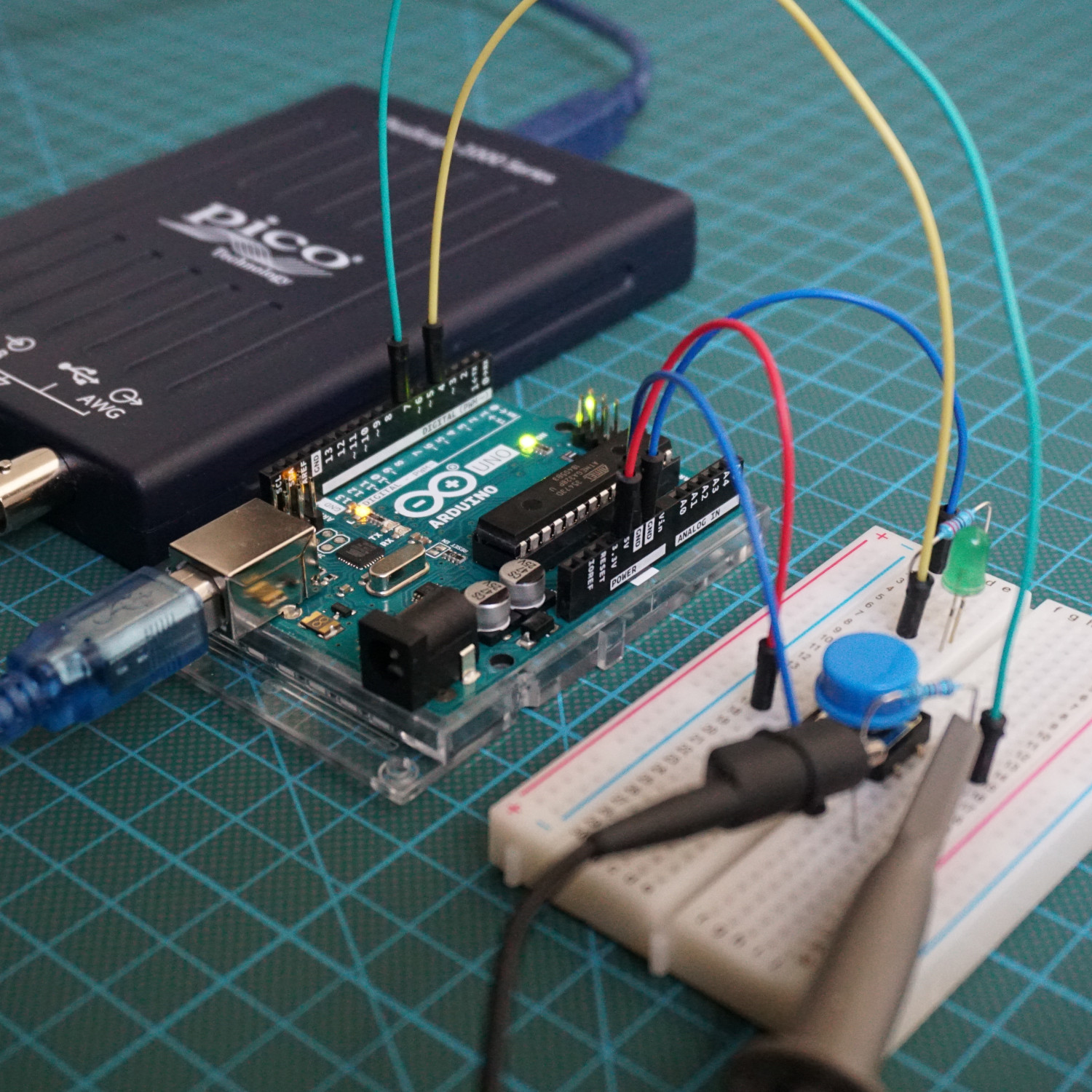
Table of Contents
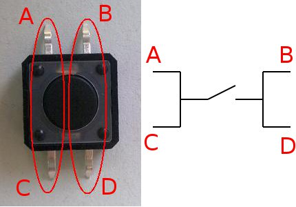
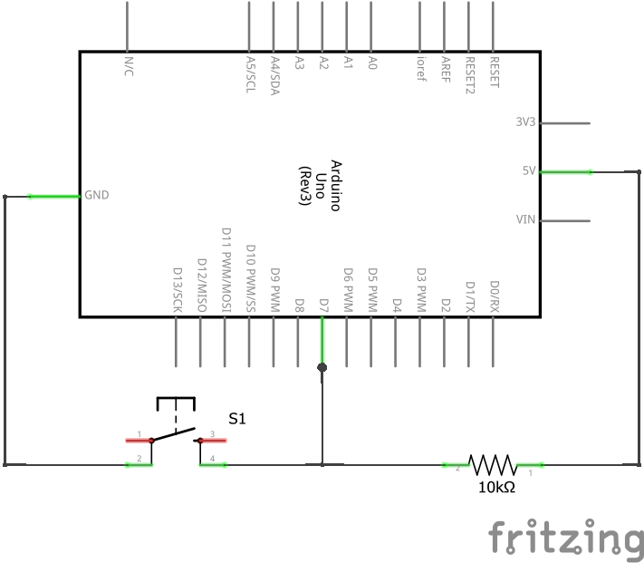
You might wonder why the four-pin switch has 4 legs. How do we have to connect the switch to other components?
If the four-pin switch is not pressed, the pins A and C are connected as well as the pins B and D. If the switch is pressed, the connection of the pins changes and all pins are wired together. Therefore there is no difference if you connect your component you want to switch on pin B or pin D of the other side of the button.
The following table gives you an overview of all components and parts that I used for this tutorial. I get commissions for purchases made through links in this table.
| Arduino Uno | Amazon | Banggood | AliExpress | |
| OR | ESP8266 NodeMCU | Amazon | Banggood | AliExpress |
| OR | ESP32 NodeMCU | Amazon | Banggood | AliExpress |
| AND | Resistor and LED in Package | Amazon | Banggood | AliExpress |
| AND | Capacitors | Amazon | Banggood | AliExpress |
| OPTIONAL | Oscilloscope | Amazon | Banggood | AliExpress |
Connect Switches and Arduino
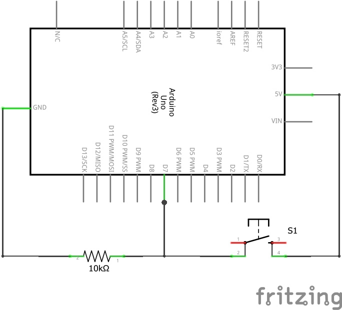
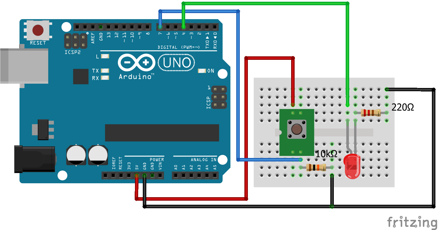
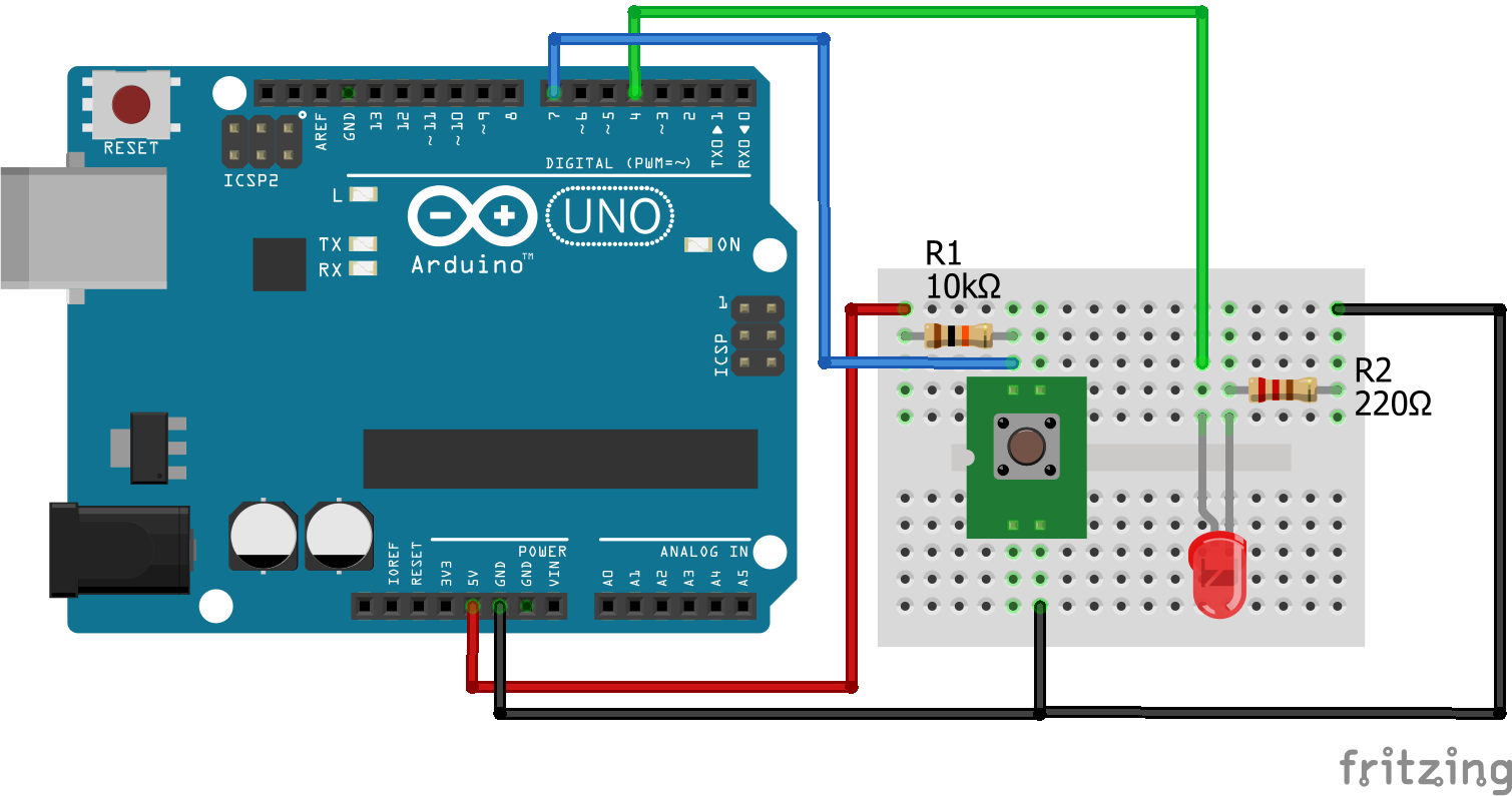
If you want to connect one or multiple switches to your Arduino it is useful to add a pull-down resistor when the signal should be LOW if the switch is open and to add a pull-up resistor if the signal should be HIGH if the switch is open. If you do not use a pull-down or pull-up resistor than, when the switch is open the digital pin is not connected to GND or to 5V. Therefore the pin state would be undefined.
The following section describes the difference between the pull-down resistor and the pull-up resistor.
Pull-Down Resistor
int switchPIN = 7;  // pin switch
int switchStatus;   // status switch
int LEDpin = 4;     // pin LED

void setup() {
Serial.begin(9600);
pinMode(LEDpin, OUTPUT);  // LED pin as output
}

void loop() {
switchStatus = digitalRead(switchPIN);   // read status of switch

// turn LED on if switch is HIGH, turn LED off if switch is LOW
digitalWrite(LEDpin, switchStatus);
}
It is possible to change the sketch that the used button has the functionality of a switch. The LED is turned on and off only if the button is pressed. Therefore the states of the LED and switch have to be stored in variables to compare the last state with the current inputs. If the button in continuously pressed the states should not be changed.
int switchPIN = 7;           // pin switch
int switchStatus;            // status switch
int switchStatusLast = LOW;  // last status switch
int LEDpin = 4;              // pin LED
int LEDStatus = LOW;         // current status LED

void setup() {
Serial.begin(9600);
pinMode(LEDpin, OUTPUT);  // LED pin as output
}

void loop() {
switchStatus = digitalRead(switchPIN);   // read status of switch
if (switchStatus != switchStatusLast)  // if status of button has changed
    {
      // if switch is pressed than change the LED status
      if (switchStatus == HIGH && switchStatusLast == LOW) LEDStatus = ! LEDStatus;
      digitalWrite(LEDpin, LEDStatus);  // turn the LED on or off
      switchStatus = switchStatusLast;
    }
}
Pull-Up Resistor
In the case of a pull-up resistor circuit, the pull down-resistor connect the digital pin and 5V. Therefore the digital input is pulled up to 5V. Only if the switch is closed, the digital pin is connected to GND.
Regarding the sketch for the pull-up resistor, we can copy the sketch of the pull-down resistor.
The switch example would be the same for the pull-up as for the pull-down. Only the initial state of the LED would be high. Therefore we do not consider the switch example for the pull-up resistor in this article.
int switchPIN = 7;  // pin switch
int switchStatus;   // status switch
int LEDpin = 4;     // pin LED

void setup() {
Serial.begin(9600);
pinMode(LEDpin, OUTPUT);  // LED pin as output
}

void loop() {
switchStatus = digitalRead(switchPIN);   // read status of switch

// turn LED on if switch is HIGH, turn LED off if switch is LOW
digitalWrite(LEDpin, switchStatus);
}
Debouncing Problem with Buttons
When a switch or button is pressed, the metal contacts in the contact points can cause the contact points to touch several times. Therefore the contact is bouncing before making a permanent contact. You might ask yourself what problem could occur due the bouncing contacts. The problem is that the Arduino clock speed is 16 MHz which results in 16 million operations per second. So the Arduino will recognize the bouncing contacts as having closed and opened the contacts several times in a row. The following picture shows this behavior on the oscilloscope when pressing a button.
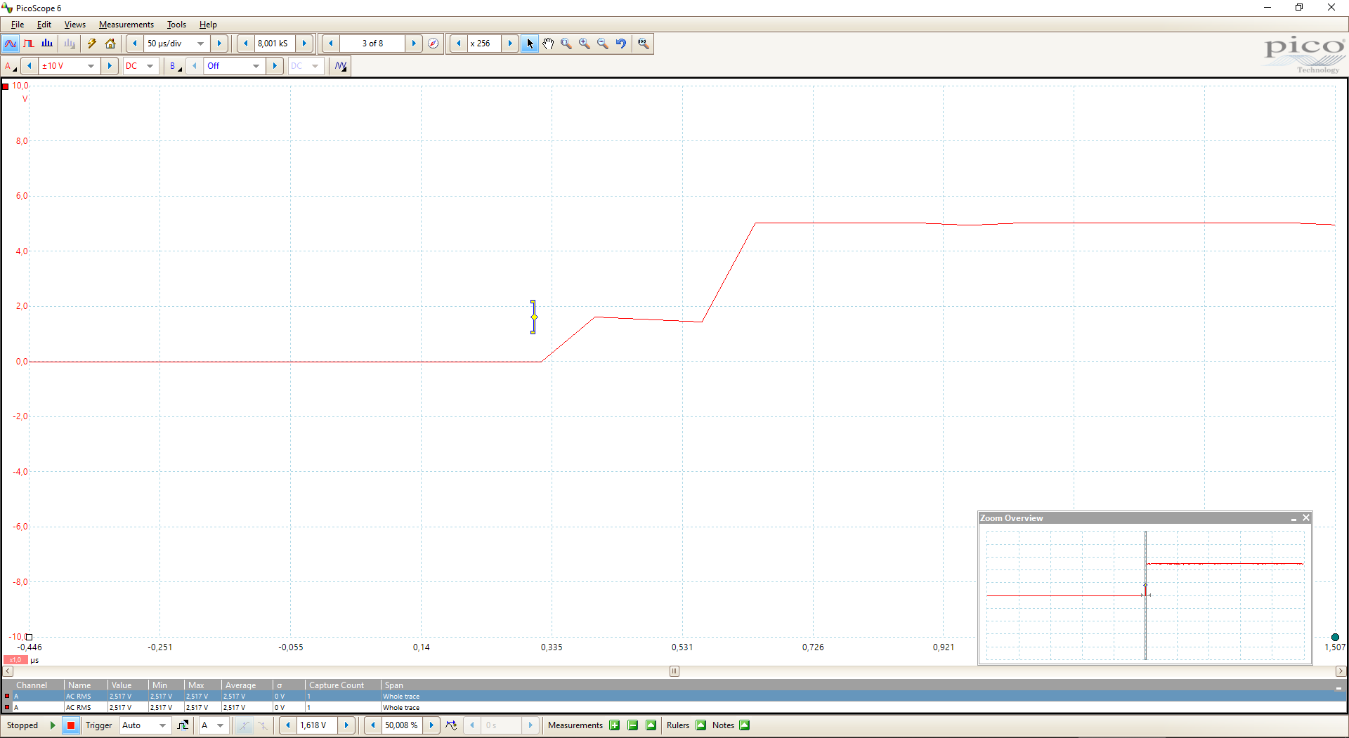
In the first picture you see clear, that when the button is pressed, the voltage only reach the around 1.8V instead of 5V. This behavior results in an LED that is not reacting when the switch or button is pressed. Only when the button is pressed a second time the internal contacts are connected and the operating voltage of 5V is reached and the LED stays on.
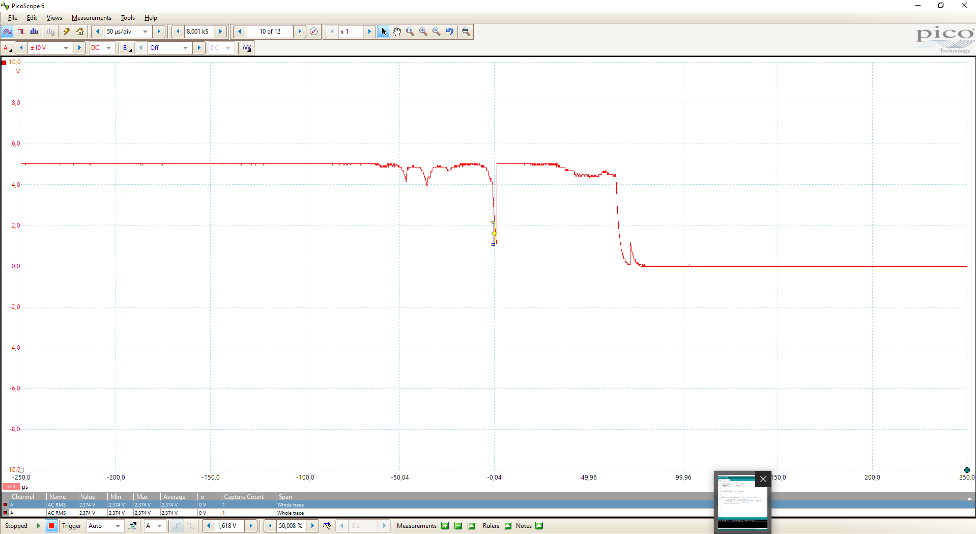
The same behavior can be shown when I try to switch the LED off in the second picture. The operating voltage is 5V and I push the button. Two times the voltage drops to around 4V and jumps back to 5V. The third time the voltage drops to around 1V but also jumpy back to 5V. Only when I push the button a forth time the switch is released and the LED goes off.
This behavior is a big problem in real live because to you want to push a button multiple times to switch on or off a light in your kitchen? I do not think so.
Good to know that there are two software and one hardware solution to fix this behavior called the debouncing problem.
Software solutions against debouncing
The first software solution is quite simple and initiates a delay and then rereads the state. The time between the two input reads is defined by a delay. If the delay is too short, the switch may be still bounding.
int switchPIN = 7;           // pin switch
int switchStatus;            // status switch
int switchStatusLast = LOW;  // last status switch
int LEDpin = 4;              // pin LED
int LEDStatus = LOW;         // current status LED

void setup() {
Serial.begin(9600);
pinMode(LEDpin, OUTPUT);  // LED pin as output
}

void loop() {
switchStatus = digitalRead(switchPIN);   // read status of switch
if (switchStatus != switchStatusLast)  // if status of button has changed
    {
      delay(50);     // debounce time of 50 ms
      switchStatus = digitalRead(switchPIN);   // read the status of the switchPIN again
      if (switchStatus != switchStatusLast) // if the status of the button has changed again
      {
        // if switch is pressed than change the LED status
        if (switchStatus == HIGH && switchStatusLast == LOW) LEDStatus = ! LEDStatus;
        digitalWrite(LEDpin, LEDStatus);  // turn the LED on or off
        switchStatus = switchStatusLast;
      }
    }
}
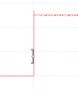
You see in the following pictures of the oscilloscope that the press and release voltage is more smoothly than without a software solution. This results in the behavior that when the button is pressed once, the LED turns on or off. The following video also shows the result of the software solution against debouncing.
Press
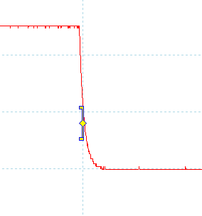
Release
A second possible software solution against debouncing is to continue delaying until there is no longer change in the switch state at the end of the debounce time. Therefore the state of the switch has to be stored at three different times:
- State before the switch was pressed (switchStatusLast)
- State during the debounce time (switchStatusDebounce)
- State when the switch was last pressed (switchStatus)
If the state has changed and is present longer than a predefined debounce time, the state of the LED can be changed. To compare the debounce time with the time, the switch was last pressed we have to define the time the switch was last pressed as unsigned long variable because the integer number has an upper limit of (2^15-1) ms or 33 seconds. The unsigned long maximum value is (2^32-1) ms or 50 days.
But there is also a much better solution than saving the state of the switch 3 times because it is also possible to solve the problem with the debouncing switch with a capacitor hardware solution.
Hardware solutions against debouncing
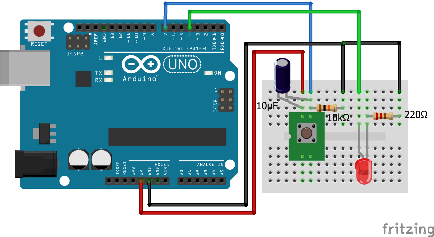
The possible hardware solution to fix the debounce problem is to use a capacitor across the switch. While the switch is not pressed, the capacitor charges. When the switch is pressed, the capacitor discharges while the switch signal to the Arduino is HIGH. During the bouncing the energy of the capacitor maintains the switch signal at HIGH. A recommended resistor-capacitor combination is 10 kΩ pull-down resistor and 10µF capacitor.
The rate which the capacitor charges and discharges depends on the resistance R and the capacitance C. The equation for the voltage of the capacitor after t seconds
- of charging is V(1-^e(-t/RC)) and
- discharging is V(e(-t/RC))
Therefore the higher the RC value, the longer is the debounce delay. The debounce delay can be expressed as 0.693 * RC seconds. With a combination of a 10 kΩ pull-down resistor and 10µF capacitor the debounce delay is 69 ms. Although the combination of resistor and capacitor is free of choice, a large resistor should be used to minimize the current through the resistor.
int switchPIN = 7;           // pin switch
int switchStatus;            // status switch
int switchStatusLast = LOW;  // last status switch
int LEDpin = 4;              // pin LED
int LEDStatus = LOW;         // current status LED

void setup() {
Serial.begin(9600);
pinMode(LEDpin, OUTPUT);  // LED pin as output
}

void loop() {
switchStatus = digitalRead(switchPIN);   // read status of switch
if (switchStatus != switchStatusLast)  // if status of button has changed
    {
      // if switch is pressed than change the LED status
      if (switchStatus == HIGH && switchStatusLast == LOW) LEDStatus = ! LEDStatus;
      digitalWrite(LEDpin, LEDStatus);  // turn the LED on or off
      switchStatus = switchStatusLast;
    }
}
Capacitor = 10µF
Capacitor = 100µF
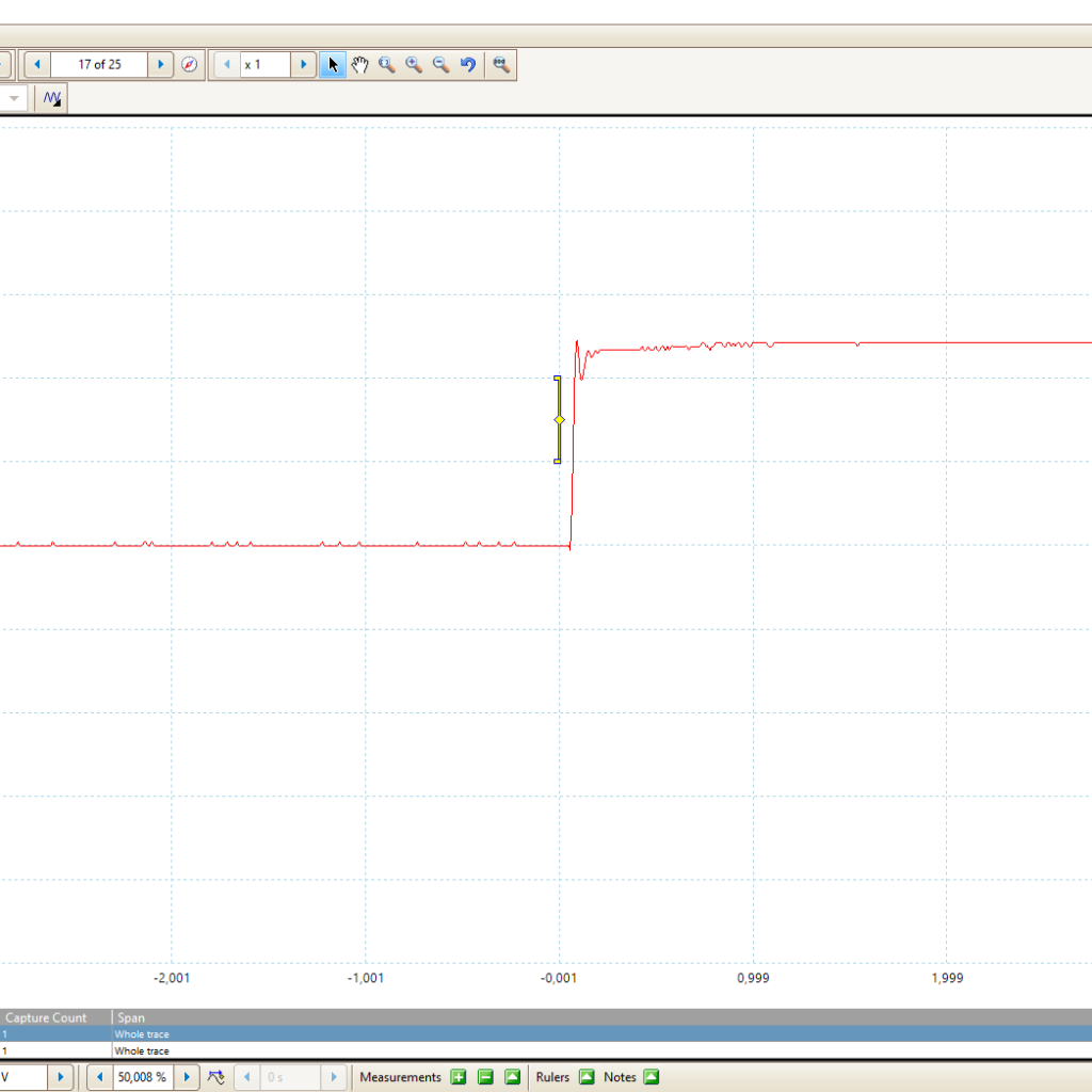
In the following picture you see the voltage rise during the button press. It is very similar to the software solution.
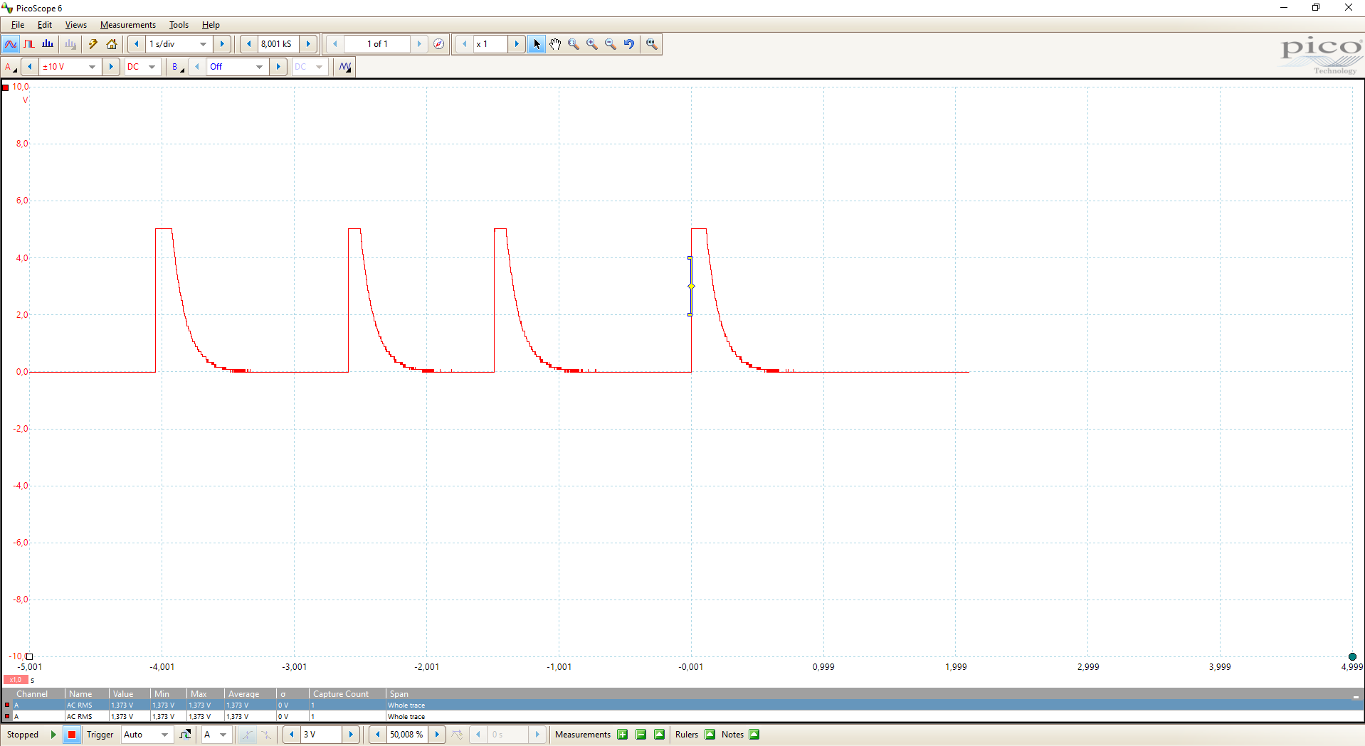
The following picture shows the voltage during the press and release phases. You see very good the impact of the capacitor reducing the voltage over time. The picture shows 4 cycles.
Conclusion
In this article you learn about different kinds of switches and the pull-up and pull down resistors, how to use them and the differences. Also you learned what the debouncing problem is. Moreover we discussed hardware and software solutions against the debouncing problem.
I hope you enjoined this article. Do you have any further questions about switches? Use the comment section below to ask your questions.
Leave A Comment