I2S Sound Tutorial for ESP32
In this tutorial you learn the fundamentals of the I2S communication that is used to transfer digital sound signals and why you should use an ESP32 microcontroller for your I2S projects.
After your learn the functionality of I2S we create 3 projects where you can apply what you have learned.
The I2S communication protocol was developed by Philips Semiconductors in 1986. I2S stands for Inter-Integrated Circuit Sound and as an electrical serial bus interface I2S is the standard to connect different digital audio devices.
ESP32 and ESP8266 microcontroller support the I2S protocol where only some special Arduino microcontroller support the communication protocol.
Table of Contents
Why do we need the I2S protocol?
If we want to play a digital audio file with the help of a microcontroller board, we have to consider the whole digital audio chain. The following schematic sketch shows how an audio file is stored on an SD card and read from the microcontroller board. The board is then connected to the speaker via a digital pin and ground.
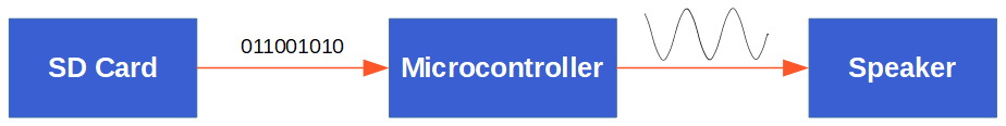
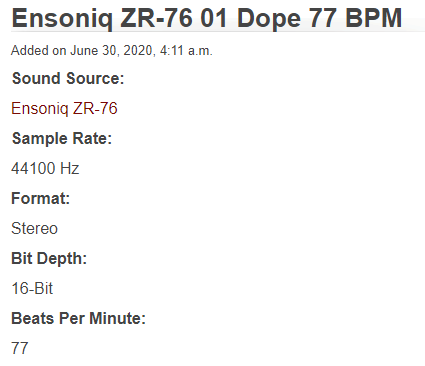
In my case I have a sample audio file from freewavesamples with a sample rate of 44.1 kHz, stereo format and a bit depth of 16 bits. On our input side, where we want to read the music file, we have no problem because the SPI connection is fast enough that the quality is not reduced during the transmission.
But on the output side we have to transfer the digital signal to an analog signal. This is done by a digital to analog converter (DAC). Depending on the used microcontroller there are different problems:
- Arduino and ESP8266: The Arduino boards as well as the ESP8266 in general do not have an internal DAC and therefore you would have to build an DAC with external components.
- ESP32: The ESP32 has an internal DAC to create an analog output signal, however the DAC has only an 8-bit resolution. Because we have a 16 bit input signal, we would loose quite some quality.
But how can we convert the digital data from the WAVE file to the speaker? The solution to this is the I2S communication protocol, that supports between 4 to 32 data bits per sample. To make our life even easier, we use an MAX98357 I2S audio breakout board. But first we dive deeper into the I2S communication protocol.
I2S Communication Protocol
In this part of the I2S tutorial we want to take a closer look at the I2S communication protocol. Therefore we cover three important topics.
- I2S 3-Wire Connection
- I2S Network Components
- I2S Timing Diagram
The following table shows which boards have an I2S interface and which boards don’t.
From the table you see that only some special Arduino boards have the I2S interface but not the most used boards like the Arduino Uno. Also all ESP8266 and ESP32 boards support the I2S interface and therefore I recommend to use either an ESP8266 or ESP32 microcontroller based board for this tutorial. In my case I use an ESP32 microcontroller because the libraries that we use supports the ESP32 better than the ESP8266 in my experience.
I2S 3-Wire Connection
The I2S protocol uses three wires for the communication.
The Serial Clock (SCK) also called the bit clock line (BCLK) is used to get all components on the same cycle. The frequency of the serial clock is defined by: Frequency = Sample Rate * Bits per channel * Number of channels.
For my WAVE file that I use in this tutorial we already know the following variables:
- Sample rate: 44.1 kHz
- Bits per channel: 16
- Number of channels: 2
Therefore the serial clock has the frequency of 44.1 kHz * 16 * 2 = 1.411 MHz.
The second line of the I2S communication protocol is the Word Select (WS) or Frame Select (FS) wire that differentiate between the left or the right channel.
- If WS = 0 → Channel 1 (left channel) is used
- If WS = 1 → Channel 2 (right channel) is used
The last wire is the Serial Data (SD) line where the payload is transmitted in 2 complements. It is important that the most significant bit is transferred fist (MSB first), because transmitter and receiver may have different word lengths. Therefore the transmitter nor the receiver have to know how many bits are transferred. But what happened if the word length between transmitter and receiver does not match?
- If WS of receiver > WS transmitter → word is truncated (least significant data bits are set to 0)
- If WS of receiver < WS transmitter → bits after the LSB are ignored
I2S Network Components
If there are multiple I2S components connected to each other, I call this an I2S network. The network components have different names and also different functions. The following picture shows three different networks, that I describe in the following section.
In the first picture we have a transmitter and also a receiver. The transmitter could be an ESP NodeMCU board and the receiver an I2S audio breakout board, that we describe in the next section. Also we do have the three wires to connect the I2S devices.
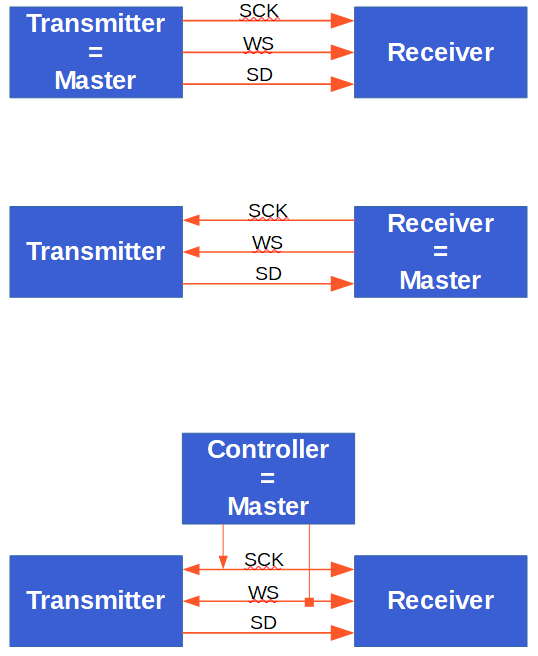
In this first case the transmitter is the master because the master controls the serial clock (SCK) and the word select (WS) lines. In the second picture we see the opposite because also the receiver of the I2S messages can be the master. Therefore the SCK and WS lines starts from the receiver and ends on the transmitter.
The third picture shows that also an external controller can be the master device that generates the SCK and WS. The controller is connected to the nodes in the network.
In all I2S networks there is only one master device. There could be multiple other components that receive or transmit sound data.
I2S Timing Diagram
To better understand the behavior and also the functionality of the I2S communication protocol, we have a look at the following I2S timing diagram.
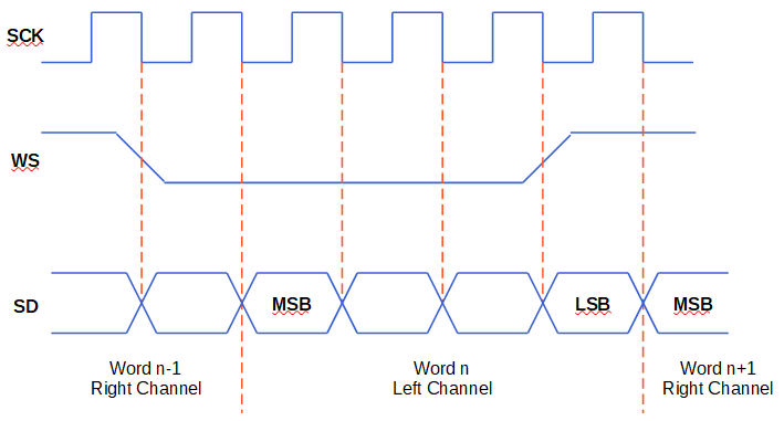
In the timing diagram you see all three lines: SCK, WS and SD. First we have our serial clock that have the frequency of Sample Rate * Bits per channel * Number of channels, in our example 1.411 MHz. The second channel is the word select line that changes between 1 for the right sound channel and 0 for the left channel.
From the serial data line we see that data is send on every clock cycle on the falling edge (red dotted line) → HIGH to LOW. For the I2S communication it is also possible to send data on a LOW to HIGH change.
Also we see that the WS line changes one clock cycle before the most significant bit (MSB) is transmitted. That gives the receiver time to store the previous word and clear the input register for the next word. The MSB is sent when SCK changes after WS changes.
The MAX98357 I2S Audio Breakout Board
After we know that we can use the I2S communication protocol to get the sound data out of the microcontroller without any reduction in quality, the next problem is, that we have to decode the I2S signals into analog signals and also need an amplifier to use a speaker.
- Decoder from I2S signal to analog signal, because speakers only work with analog signals.
- Amplifier increases the power of the analog signal to increase the sound intensity.
The MAX98357 is a digital pulse-code modulation (PCM) input amplifier that decodes the I2S signal in an analog signal with a digital to analog converter (DAC) and has also a build in amplifier. The following picture shows the simplified block diagram from the MAX98357 datasheet.
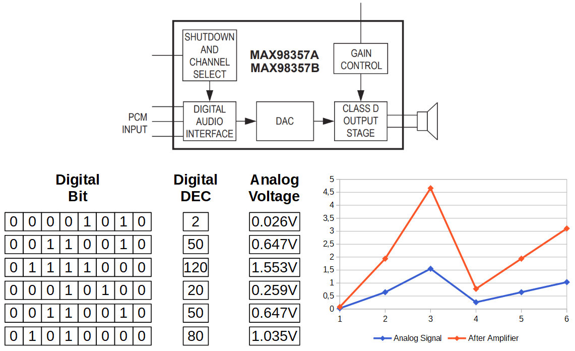
From the block diagram of the MAX98357 you see that first the I2S signal is transformed into an analog signal via the DAC and afterwords boosted by the amplifier with a predefined gain control.
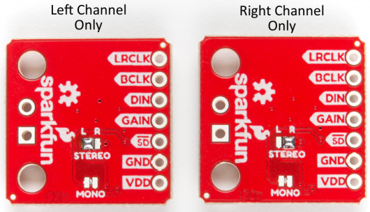
You can buy the MAX98357 on a breakout board from Adafruit or SparkFun. The products are exactly the same. The following table shows the datasheet of the MAX98357.
The operation voltage of the MAX98357 is between 2.7V and 5.5V. Therefore you can power the microcontroller with an Arduino (5V) or ESP (3.3V) based board. The output power is 3.2W for a 4Ω speaker and 1.8W for a speaker with 8Ω.
The default configuration of the board is “mono” operation, meaning the left and right signals are combined together to drive a single speaker. If you want to switch to stereo sound, you have to cut the mono jumper on the PCB and solder the stereo connection either for the left or the right channel.
The sample rate of the MAX98357 is between 8kHz – 96kHz and therefore our example music with 44.1 kHz fits perfectly in the sample rate. The sample resolution is 16 bit or 32 bit and the quiescent current is very low with 2.4 mA.
Because the amplifier uses pulse-width modulation to control the output devices, it is a class D amplifier. The gain rate of the amplifier is between 3dB and 15dB with a default gain rate of 9dB. The following table shows how to change the gain rate. Key is that the gain pin has to be connected to other pins to change the gain rate.
The following table gives you an overview of all components and parts that I used for this tutorial. I get commissions for purchases made through links in this table.
Record and visualize data with an I2S microphone
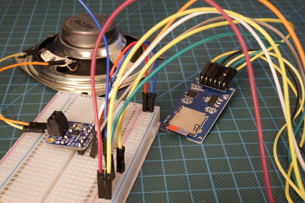
In the first example we start to record and visualize sound data from an I2S microphone microcontroller SPH0645 from adafruit. For this example we use the ESP32 NodeMCU microcontroller.
The following picture shows the wiring between the ESP32 NodeMCU and the SPH0645 breakout board.
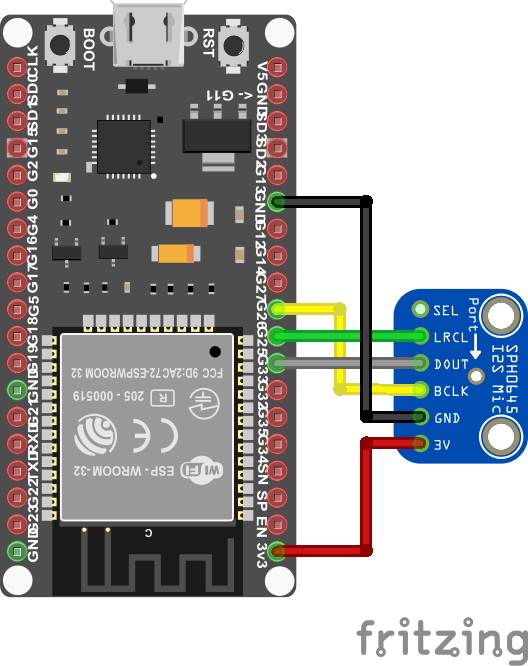
It is important to connect the I2S microcontroller only to the 3.3V pin. The following Arduino code visualize the analog sound data in the Arduino Serial Plotter.
#include "driver/i2s.h"

const i2s_port_t I2S_PORT = I2S_NUM_0;

void setup() {
  Serial.begin(115200);
  esp_err_t err;

  // The I2S config as per the example
  const i2s_config_t i2s_config = {
      .mode = i2s_mode_t(I2S_MODE_MASTER | I2S_MODE_RX), // Receive, not transfer
      .sample_rate = 16000,                         // 16KHz
      .bits_per_sample = I2S_BITS_PER_SAMPLE_32BIT, // could only get it to work with 32bits
      .channel_format = I2S_CHANNEL_FMT_ONLY_RIGHT, // use right channel
      .communication_format = i2s_comm_format_t(I2S_COMM_FORMAT_I2S | I2S_COMM_FORMAT_I2S_MSB),
      .intr_alloc_flags = ESP_INTR_FLAG_LEVEL1,     // Interrupt level 1
      .dma_buf_count = 4,                           // number of buffers
      .dma_buf_len = 8                              // 8 samples per buffer (minimum)
  };

  // The pin config as per the setup
  const i2s_pin_config_t pin_config = {
      .bck_io_num = 26,   // Serial Clock (SCK)
      .ws_io_num = 25,    // Word Select (WS)
      .data_out_num = I2S_PIN_NO_CHANGE, // not used (only for speakers)
      .data_in_num = 33   // Serial Data (SD)
  };

  // Configuring the I2S driver and pins.
  // This function must be called before any I2S driver read/write operations.
  err = i2s_driver_install(I2S_PORT, &i2s_config, 0, NULL);
  if (err != ESP_OK) {
    Serial.printf("Failed installing driver: %d\n", err);
    while (true);
  }
  err = i2s_set_pin(I2S_PORT, &pin_config);
  if (err != ESP_OK) {
    Serial.printf("Failed setting pin: %d\n", err);
    while (true);
  }
  Serial.println("I2S driver installed.");
}

void loop() {

  // Read a single sample and log it for the Serial Plotter.
  int32_t sample = 0;
  int bytes_read = i2s_pop_sample(I2S_PORT, (char *)&sample, portMAX_DELAY); // no timeout
  if (bytes_read > 0) {
    Serial.println(sample);
  }

}
In the first line we include the I2S library for the ESP32 and define the used I2S Pin structure because only GPIO25 and GPIO26 are connected to an internal 8-bit DAC, that is also shown in the ESP32 pinout.
In the setup function we set the baud rate to 115200 that have to match the baud rate in the serial plotter of the Arduino IDE, where we display the analog sound data.
If we get any error during the execution of the code we can access the error with the variable err.
The next step in the Arduino code is to define the structure of the I2S communication. We set the following settings:
- set the I2S Mode to RX to receive I2S data
- use a default sample rate of 16 kHz
- set the bits per sample to 32 and not 16
- we use only the right channel of the microphone
- we use 4 buffers, each with a length of 8
After we set the structure of the I2S communication, we define the pins that are used on the ESP32 NodeMCU for the communication. In my case I choose:
- Serial Clock (SCK) = 26
- Word Select (WS) = 25
- Serial Data (SD) = 33
In the following section, the I2S driver and pins are configured. Because this part of the code dives deep into the internal functions of the ESP32, we skip the explanation of this section.
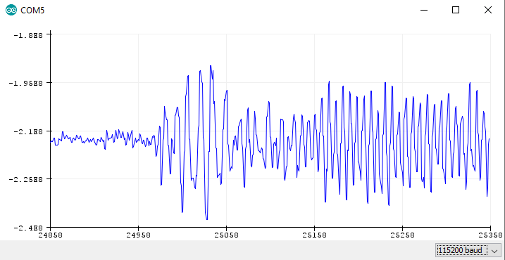
In the loop function, we read the analog output from the DAC and save the data in the bytes_read variable. If we receive data, we print the analog audio signal to the serial output to visualize the audio frequency in the serial plotter.
The following picture shows the analog output of the serial monitor if I play some music from my PC and the microphone is listening.
Play Music from the internal ESP32 memory
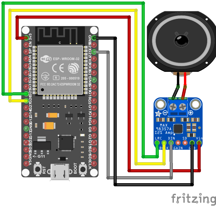
In the second example we want to play music with a speaker. The sound data is stored as array in the internal RAM of the ESP32. We use the MAX98357 I2S audio breakout board to decodes the digital signal to an analog signal. Therefore we use the I2S protocol to output the digital sound data without any quality losses.
The following picture shows the wiring between the ESP32 NodeMCU, the MAX98357 I2S audio breakout board and the speaker.
For the Arduino code we use the ESP8266Audio library from Earle F. Philhower. To include this library to your Arduino, follow the 4 steps:
- Download the github folder as zip file
- unzip the downloaded folder
- rename the unzipped folder to ESP8266Audio
- copy the folder to your Arduino IDE library path (in my case: C:\Users\chris\Documents\Arduino\libraries)
We use the following Arduino code from the library examples to play music from the internal memory.
#include "AudioGeneratorAAC.h"
#include "AudioOutputI2S.h"
#include "AudioFileSourcePROGMEM.h"
#include "sampleaac.h"

AudioFileSourcePROGMEM *in;
AudioGeneratorAAC *aac;
AudioOutputI2S *out;

void setup()
{
  Serial.begin(115200);

  in = new AudioFileSourcePROGMEM(sampleaac, sizeof(sampleaac));
  aac = new AudioGeneratorAAC();
  out = new AudioOutputI2S();
  out -> SetGain(0.125);
  out -> SetPinout(26,25,22);
  aac->begin(in, out);
}

void loop()
{
  if (aac->isRunning()) {
    aac->loop();
  } else {
    aac -> stop();
    Serial.printf("Sound Generator\n");
    delay(1000);
  }
}
In the first lines we add the following header files from the ESP8266Audio library:
- AudioGeneratorAAC: Audio output generator using the Helix AAC decoder
- AudioOutputI2S: Base class for I2S interface port
- AudioFileSourcePROGMEM: Store a “file” as a PROGMEM array and use it as audio source data
- sampleaac: Header file that stores the audio file as array
The digital sound data is stored in the sampleaac header file. To upload the Arduino code with the header file to the EPS32, it is important that the Arduino (.ino file) and the header (.h file) are in the same folder.
After we include the header files of the ESP8266Audio library, we give the first three of them a short variable, that contain functions.
In the setup function, we set the baud rate to 115200 and initialize the header files. For the AudioFileSourcePROGMEM, we define that the sample audio file is in the sampleaac file with the size of the containing array.
The AudioOutputI2S object has different functions. We use the SetGain function to reduce the volume of the speaker and we define the pinout with the SetPinout function. In my case I choose the default pinout that is the following:
- Serial Clock (SCK) = 26
- Word Select (WS) = 25
- Serial Data (SD) = 22
But feel free to choose other digital pins of your EPS32 microcontroller.
The last step of the setup function is to connect the input sound data from the internal program memory to the I2S audio output with the AudioGeneratorAAC begin function.
In the loop function the audio generator continues running until the whole sound array is run through the generator. When the generator is done, it stops running and in the serial output we can see that the sound generator is done.
Play a WAVE file from an external SD card
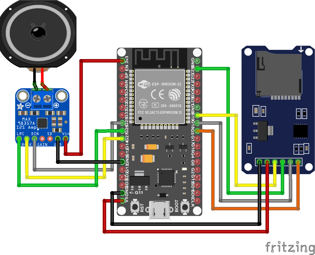
In our last project we want to play the WAVE file that I mentioned at the beginning of this tutorial via the ESP32 NodeMCU and the speaker. Because the ESP32 have to read the WAVE file and forward the digital audio signal to the MAX98357A, we have to use a SD card with the WAVE file on it. You can also use an MP3 file instead of the WAVE file.
The following picture shows the wiring of the ESP32 NodeMCU with the (Micro) SD card module, the MAX98357A and speaker. From the picture you see, that you have to change the DIN pin of the MAX98357A, compared to the second project.
Before we dive in to the Arduino code, we have to prepare the (Micro) SD card. The file system has to be FAT16 or FAT32. Depending on the SD card module there is a limit of 32GB for the SD card. I use a 32GB micro SD card formatted as FAT32 and copy the WAVE file with no folder on to the SD card.
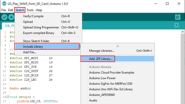
For this project we use the ESP32-audioI2S Arduino library from schreibfaul1. You can download the library as zip file from his gibhub page. Because the library is included with the name audio, and there is already an Arduino library that has the same name, we include the library via the Arduino IDE:
- Open the Arduino IDE
- Navigate to (see the following picture): Sketch → Include Library → Add .ZIP Library
- Select the downloaded library
The Arduino script is based on the example script of schreibfaul1, but I reduced the script to the parts that are necessary to play the WAVE file and deleted all parts for the WiFi streaming.
#include "Audio.h"
#include "SD.h"
#include "FS.h"

// Digital I/O used
#define SD_CS          5
#define SPI_MOSI      23
#define SPI_MISO      19
#define SPI_SCK       18
#define I2S_DOUT      25
#define I2S_BCLK      27
#define I2S_LRC       26

Audio audio;

void setup() {
    pinMode(SD_CS, OUTPUT);
    digitalWrite(SD_CS, HIGH);
    SPI.begin(SPI_SCK, SPI_MISO, SPI_MOSI);
    Serial.begin(115200);
    SD.begin(SD_CS);
    audio.setPinout(I2S_BCLK, I2S_LRC, I2S_DOUT);
    audio.setVolume(10); // 0...21
    audio.connecttoFS(SD, "Ensoniq-ZR-76-01-Dope-77.wav");
}

void loop()
{
    audio.loop();
}

// optional
void audio_info(const char *info){
    Serial.print("info        "); Serial.println(info);
}
void audio_id3data(const char *info){  //id3 metadata
    Serial.print("id3data     ");Serial.println(info);
}
void audio_eof_mp3(const char *info){  //end of file
    Serial.print("eof_mp3     ");Serial.println(info);
}
void audio_showstation(const char *info){
    Serial.print("station     ");Serial.println(info);
}
void audio_showstreaminfo(const char *info){
    Serial.print("streaminfo  ");Serial.println(info);
}
void audio_showstreamtitle(const char *info){
    Serial.print("streamtitle ");Serial.println(info);
}
void audio_bitrate(const char *info){
    Serial.print("bitrate     ");Serial.println(info);
}
void audio_commercial(const char *info){  //duration in sec
    Serial.print("commercial  ");Serial.println(info);
}
void audio_icyurl(const char *info){  //homepage
    Serial.print("icyurl      ");Serial.println(info);
}
void audio_lasthost(const char *info){  //stream URL played
    Serial.print("lasthost    ");Serial.println(info);
}
void audio_eof_speech(const char *info){
    Serial.print("eof_speech  ");Serial.println(info);
}
In the first part of the Arduino script for the ESP32, we include all libraries and define the pins that are used to connected the ESP32 NodeMCU to the MAX98357A and the SD card module.
After the Audio object is initialized with the name “audio”, the setup function is called. In the setup function, the pins and the SPI connection for the SD card communication is defined. The baud rate is set to 115200 and the SD card object is also initialized.
For the audio object, the previous pins are set to the pinout and we reduce the sound volume to 10. You can adjust the sound volume between 0 and 21. The last part of the setup function is to connect the inputs and outputs of this example. Therefore we connect the audio object with the SD card object and define the path to the WAVE file. If you put the sound file into a folder, you have to copy the whole path to the sound file with forward slashes (“/”).
In the loop function we only have to loop over the preconfigured audio object to play the music.
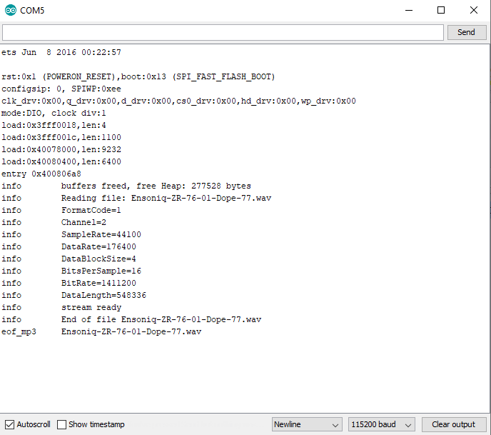
The last part is interesting if you want to print some details of the sound file in the serial monitor. The following picture shows the serial output in my example. The first section are booting information of the ESP32 that are shown to the serial monitor if the baud rate is set to 115200.
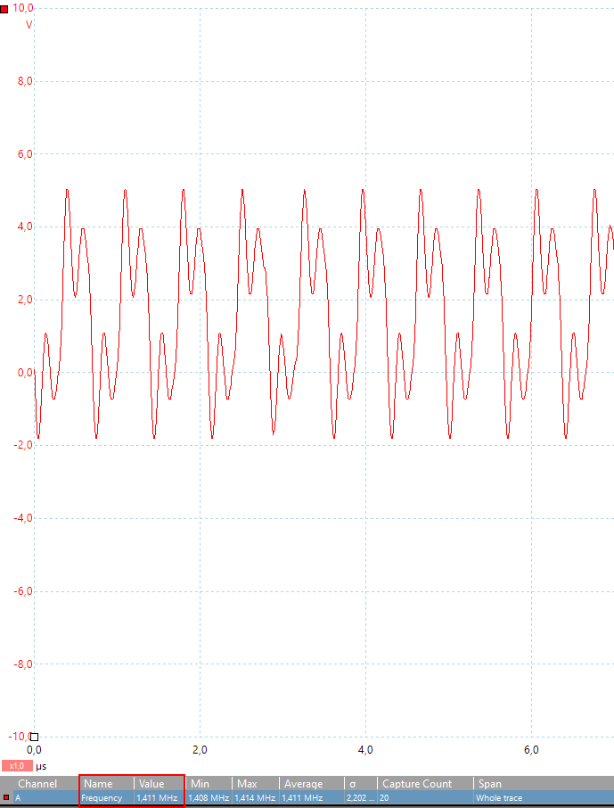
In the first part of this article I calculated the frequency of the serial clock 44.1 kHz * 16 * 2 = 1.411 MHz. Now I want to prove if the serial clock I2S connection between the ESP32 and the MAX98357A is 1.411 MHz. Therefore I connected the CLK line to my USB oscilloscope and add the measurement for the frequency.
The following picture shows that my calculation was correct and the frequency is 1.411 MHz.
If you have any questions regarding the I2S communication in general or if you are struggling to create the example projects, please use the comment section below to ask questions. I will answer them as soon as possible.
Hello
Thanks so much for this great explanation!
Did you also acheive to output two sounds simultaneously? Elsewhere I read, that this is only possible, if we use the internal memory (as in your second example).
By the way: my goal is to build my own diy-sampler / diy-drum machine. For this use it would be great to play more than just one sample at the time.
Thanks for your help!
Timon
Thanks for the great examples! I’m a newbie with I2S and digital audio. These provide a good start.
Hi. Can we also run the audio files from a pen drive? Like we have in our home system?
hello,
I want to us an i2s mic so when i talk i can hear my self from the other side i wrote this Programm below using the buffer and the left and right side of the esp32 but it seems not to be working can you help me
tim
#include “esp_system.h”
#include “esp_log.h”
#include “driver/i2s.h”
#include “freertos/ringbuf.h”
#include
#include
// micro port
#define I2S_PORT I2S_NUM_1
// haut parleur Port
#define I2S_PORT_0 I2S_NUM_0
//haut parleur
#define I2S_WS_PIN_OUT 22
#define I2S_SCK_PIN_OUT 26
#define I2S_DATA_PIN_OUT 25
// micro
#define I2S_IN_NUM (1)
#define I2S_IN_BCK_IO (GPIO_NUM_14)
#define I2S_IN_WS_IO (GPIO_NUM_33)
#define I2S_IN_DO_IO (-1)
#define I2S_IN_DI_IO (GPIO_NUM_32)
#include
char* i2s_read_buff;
char* ptr_write_buff;
char* i2s_write_buff;
//SPH0645 Microfon // 32-Bit Modus, 24 Bit Daten, 2er-Komplement, MSB first, Rest wird mit 0 rausgetaktet
// SEL wird für linker/rechter Kanal benötigt
// SEL hier: GND
static const char *TAG = “I2s”;
//buf_len = 1024; // 8 Bytes pro gelesenes Sample => 128 Samples => 3ms Buffer
//buf_len = 4096; // 8 Bytes pro gelesenes Sample => 512 Samples => 12ms Buffer
//buf_len = 8192; // 8 Bytes pro gelesenes Sample => 1024 Samples => 24ms Buffer
#define buf_len (8192)
void setup()
{
i2s_setpin();
i2s_start(I2S_PORT);
i2s_start(I2S_PORT_0);
}
void loop()
{
}
void task_megaphone(void *pvParams)
{
char *buf = (char *)calloc(buf_len, sizeof(char));
struct timeval tv = {0};
struct timezone *tz = {0};
gettimeofday(&tv, &tz);
uint64_t micros = tv.tv_usec + tv.tv_sec * 1000000;
uint64_t micros_prev = micros;
uint64_t delta = 0;
uint32_t delta2=0;
int16_t value_16bit=0;
char*p_value_16bit= (char*)&value_16bit;
int cnt = 0;
uint16_t i=0;
int bytes_to_write = 0;
size_t bytes_written=0;
while(1)
{
char*buf_ptr_read = buf;
char*buf_ptr_write = buf;
// read whole block of samples
size_t bytes_read = 0;
while(bytes_read == 0) i2s_read(I2S_PORT, buf, buf_len, &bytes_read,10);
// Mikrophone liefert 32 Bit pro Kanal (L/R) – also 4 Bytes pro Kanal;
// Mikrophone liefert also 8 Bytes links und rechtes zusammen
uint32_t samples_read = bytes_read / 8; // 2 / (I2S_BITS_PER_SAMPLE_32BIT / 8);
// Mikrofon gibt nur Mono aus
// convert 2x 32 bit stereo -> 1 x 16 bit mono
float max=0;
for(i = 0; i max) max=abs(value_16bit);
buf_ptr_write += 4; //2 * (I2S_BITS_PER_SAMPLE_16BIT / 8);
buf_ptr_read += 8; //2 * (I2S_BITS_PER_SAMPLE_32BIT / 8);
}
cnt += samples_read;
if(cnt >= 44100) {
gettimeofday(&tv, &tz);
micros = tv.tv_usec + tv.tv_sec * 1000000;
delta = micros – micros_prev;
micros_prev = micros;
delta2=delta;
cnt = 0;
}
buf_ptr_write = buf;
for(i = 0; i < samples_read; i++) {
buf_ptr_write[0] = *p_value_16bit++; // low
buf_ptr_write[1] = *p_value_16bit; // high
// right
buf_ptr_write[2] = buf_ptr_write[0]; // low
buf_ptr_write[3] = buf_ptr_write[1]; // high
// Ausgabe (write) hat 4 Bytes pro Sample (2×2 Bytes = 2×16 Bit)
buf_ptr_write += 4; //2 * (I2S_BITS_PER_SAMPLE_16BIT / 8);
}
// local echo
//rechne Anzahl zu schreibende Byes aus:
bytes_to_write = samples_read * 4; //2 * (I2S_BITS_PER_SAMPLE_16BIT / 8);
i2s_write(I2S_PORT_0, buf, bytes_to_write, &bytes_written,portMAX_DELAY);
}
}
void i2s_install()
{
const i2s_config_t i2s_config_in =
{
.mode = i2s_mode_t(I2S_MODE_MASTER | I2S_MODE_RX),
.sample_rate = 44100,
.bits_per_sample = i2s_bits_per_sample_t(32),
.channel_format = I2S_CHANNEL_FMT_RIGHT_LEFT,
.communication_format = i2s_comm_format_t(I2S_COMM_FORMAT_I2S | I2S_COMM_FORMAT_I2S_MSB),
.intr_alloc_flags = ESP_INTR_FLAG_LEVEL1, // default interrupt priority
.dma_buf_count = 14,
.dma_buf_len = 64,
};
const i2s_config_t i2s_config_out =
{
.mode = i2s_mode_t(I2S_MODE_MASTER | I2S_MODE_TX),
.sample_rate = 44100,
.bits_per_sample = i2s_bits_per_sample_t(16),
.channel_format = I2S_CHANNEL_FMT_RIGHT_LEFT,
.communication_format = i2s_comm_format_t(I2S_COMM_FORMAT_I2S | I2S_COMM_FORMAT_I2S_MSB),
.intr_alloc_flags = 0, // default interrupt priority
.dma_buf_count = 32,
.dma_buf_len = 64,
.use_apll = 0,
.tx_desc_auto_clear= true
};
i2s_driver_install(I2S_PORT, &i2s_config_in, 0, NULL);
i2s_driver_install(I2S_PORT_0, &i2s_config_out, 0, NULL);
}
void i2s_setpin()
{
const i2s_pin_config_t pin_config_in =
{
.bck_io_num = I2S_IN_BCK_IO,
.ws_io_num = I2S_IN_WS_IO,
.data_out_num = I2S_IN_DO_IO,
.data_in_num = I2S_IN_DI_IO ,
};
const i2s_pin_config_t pin_config_out =
{
.bck_io_num =I2S_SCK_PIN_OUT ,
.ws_io_num = I2S_WS_PIN_OUT,
.data_out_num = I2S_PIN_NO_CHANGE,
.data_in_num = I2S_DATA_PIN_OUT,
};
i2s_set_pin(I2S_PORT, &pin_config_in);
i2s_set_pin(I2S_PORT_0, &pin_config_out);
}
void app_main(void) {
i2s_install();
i2s_setpin();
i2s_start(I2S_PORT);
i2s_start(I2S_PORT_0);
xTaskCreate(&task_megaphone, "task_megaphone", 16384, NULL, 20, NULL);
while (1)
{
vTaskDelay(1000 / portTICK_PERIOD_MS);
}
}
I have a Wifi + Bluetooth Module that has i2s protocol. Although their entries are different, they are:
BT_PCM_SYNC
BT_PCM_CLK
BT_PCM_IN
BT_PCM_OUT
How can I use these connectors on Arduino?
El Chip es un rtl8723as
https://spanish.alibaba.com/product-detail/-ble-wifi-module-60401082125.html