MH-Z14A CO2 Meter Tutorial with Arduino, ESP8266 or ESP32
The objective of this MH-Z14A CO2 meter tutorial is that you learn the basic functionality of the MH-Z14A and how this CO2 sensor can be useful in times of Corona.
You learn how to build a CO2 alarm that can be used in the office and how to use the three communication interfaces of the MH-Z14A in combination with different Arduino, ESP8266 and ESP32 microcontroller.
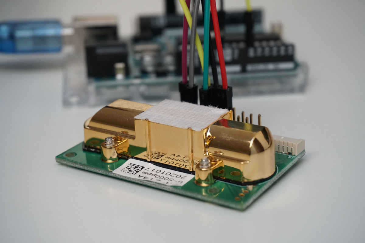
Table of Contents
Why is the CO2 Measurement Important in Times of Corona?
The major cause by which people are infected with SARS-CoV-2 (the virus that causes COVID-19) is through exposure to respiratory droplets, carrying the infectious virus.
Respiratory droplets are produced during exhalation (breathing, speaking, singing, coughing, sneezing, …). The size of these droplets differs and are divided basically into two categories:
- Larger droplets
- Smaller droplets and particles
We want to focus on these smaller droplets and particles that are transmitted by airborne transmission where infectious person producing respiratory droplets for an extended time (>30 minutes to multiple hours) in an enclosed space like an office. After that time, enough virus is present in the air to cause infections in people that are more than 6 feet away.
We can avoid airborne transmission by ventilation, for example open windows in offices or classrooms. The objective is to avoid a high concentration of respiratory droplets and particles in the air.
But when is the concentration reached, that I should open the windows in my office? It is extremely hard to measure the concentration of respiratory droplets in the air. But we can measure the carbon dioxide (CO2) concentration in the air that is exhaled during the breathing. This CO2 concentration is proportional to the concentration of respiratory droplets in the air.
Therefore, this tutorial has the objective to build a CO2 meter, that tells you when the concentration of respiratory droplets is reached to open the windows to reduce the risk of an COVID-19 infection.
How to Measure the CO2 Concentration in the Air?
The concentration of carbon dioxide can be measured via an infrared (IR) radiation detector because CO2 IR radiation in a characteristic unique manner that is defined by the wavelength. The following picture shows the wavelength of different gases and their absorption strength.
At a wavelength of around 4250nm, the absorption of CO2 is the highest. Therefore, an IR CO2 detector is able to measure the concentration of CO2 in the air if all other wavelengths are not present for the measurement. The following picture shows the layout of an IR detector.
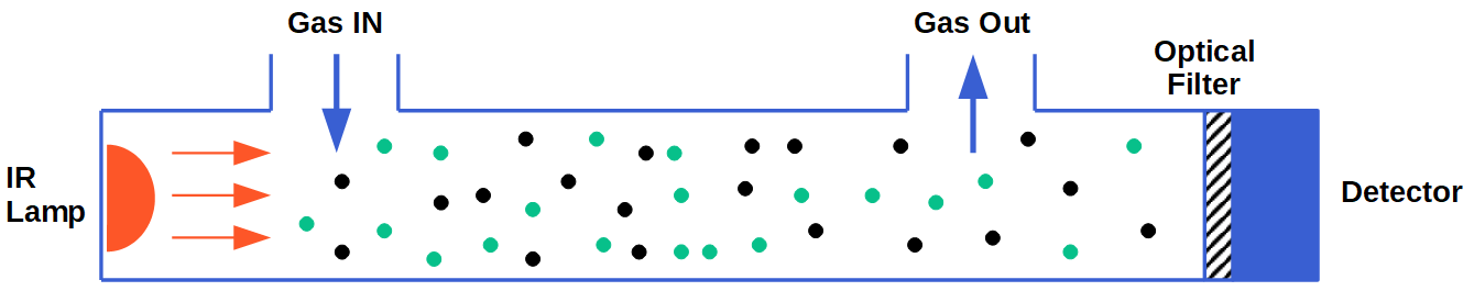
From the picture you see that there is an entrance and exit for the gas. The infrared lamp created an IR radiation through the measured gas. This IR radiation is filtered by the interference filter to the desired gas that should be measured, in our case CO2. The filter prevents that other wavelength than CO2 hit the IR detector. The IR detector measures the light intensity and coverts this intensity to a gas concentration value that has the unit parts per million (ppm).
Like all gases, the concentration depends on the temperature and pressure. The standard ambient temperature is 25°C and the pressure is 1013hPa. The equation to calculate the gas concentration on different temperatures and pressures is p = p(25°C,1013hPa) * p/1013 * 298/(273+t)
We could dive deep into the theory at this part, but the good thing is that the CO2 sensor that we use has a build in temperature compensation.
MH-Z14A CO2 Sensor
For our Corona CO2 sensor, we use the MH-Z14A that has an operation voltage between 4.5V and 5.5V. Therefore, the CO2 sensor can run on all Arduino microcontroller with an operation voltage of 5V. For ESP8266 and ESP32 microcontroller with an operation voltage of 3.3V, we have to use the 5V output from the USB connection.
During the operation of the MH-Z14A the current consumption is around 100mA and therefore not suitable for a battery powered project.
At the initial start of the CO2 sensor, the IR lamp needs around 3 minutes for preheating to create an optimal IR radiation through the measured gas. We can use this information of the setup function later in the Arduino script, where we pause the whole script for 3 minutes before we read any sensor values.
The CO2 measurement range is between 0….5000ppm with a measurement accuracy of around +- 50ppm. Regarding the Federation of European Heating, Ventilation and Air Conditioning Association (REHVA) a well-ventilated room has a CO2 concentration under 800ppm (our warning trigger) and should be under 1000ppm (our alarm trigger)
MH-Z14A Baseline Correction
The MH-Z14A has a build in temperature compensation, called automatic baseline correction (ABC), to measure accurate CO2 values also after changing the room with different temperatures. The baseline for the CO2 sensor is that the CO2 level must be 400ppm, that equals the CO2 level of the outside air. Therefore the sensor collects measurement over a time-span of 24 hours and set the minimum internal sensor value equal to 400ppm. There are two ways to activate the automatic baseline correction:
- Connect pin 8 to GND for a least 7 seconds.
- Send a specific byte combination via the UART interface, see Program Code for Aerosols Alarm.
MH-Z14A Communication Interfaces
There are in total three options to read the sensor values from the MH-Z14A that are described in detail in the following sections.
MH-Z14A Analog Interface
There are in total two different analog outputs of the MH-Z14A that differs in the output voltage of the analog output.
- Vout1 has a. output voltage between 0V and 2.5V for an output range between 0ppm and 5000ppm.
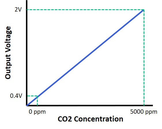
- Vout2 has a. output voltage between 0.4V and 2V for an output range between 0ppm and 5000ppm.
Because the voltage range of Vout1 is higher, we can get a more detailed measurement from Vout1, that we want to use for our CO2 alarm in this article.
To calculate the CO2 concentration, we must do the following steps:
- Read the analog value with the analogRead function.
- Recalculate the analog voltage based on the operation voltage of the microcontroller and the maximum value of the analog-to-digital converter (ADC) of the microcontroller.
- Calculate the gas concentration based on the following gradient triangle.
If you can not remember the operation voltage or maximum ADC value of the different microcontroller, the following table shows an overview for the used microcontroller in this tutorial. You can also download the Microcontroller Datasheet Wallpaper, where you find additional information about the different Arduino, ESP8266 and ESP32 boards.
| Microcontroller | Operation Voltage | ADC Value Range |
|---|---|---|
| Arduino | 5V | 0…1023 |
| ESP8266 | 3.3V | 0…1023 |
| ESP32 | 3.3V | 0…4095 |
Now we can dive into the equations to calculate the CO2 concentration from the MH-Z14A when you use the Vout1 or Vout2 pin of the MH-Z14A.
Formulars when Vout1 is used to calculate the gas concentration.
| Microcontroller | Analog Voltage | Gas Concentration |
|---|---|---|
| Arduino | float v = analogRead(analogPin) * 5.0 / 1023; | int gas_concentration = int((v-0) * (5000/2)); |
| ESP8266 | float v = analogRead(analogPin) * 3.3 / 1023; | |
| ESP32 | float v = analogRead(analogPin) * 3.3 / 4095; |
Formulars when Vout2 is used to calculate the gas concentration.
| Microcontroller | Analog Voltage | Gas Concentration |
|---|---|---|
| Arduino | float v = analogRead(analogPin) * 5.0 / 1023; | int gas_concentration = int((v-0.4) * (5000/(2-0.4)); |
| ESP8266 | float v = analogRead(analogPin) * 3.3 / 1023; | |
| ESP32 | float v = analogRead(analogPin) * 3.3 / 4095; |
MH-Z14A UART Interface
If you do not want to calculate the CO2 concentration, you can read the value for the CO2 concentration directly via the UART interface. The settings for the UART communication are the standard ones and listed in the following table.
| Baud rate | 9600 |
| Date byte | 8 bytes |
| Stop byte | 1 byte |
| Calibration byte | none |
The UART communication process the following:
- The microcontroller sends a predefined 9 bytes array via UART to the MH-Z14A.
- The MH-Z14A answers, depending on the content of the array with an 9 bytes answer array that the microcontroller reads.
- The answer array contains a high-level concentration (byte 2) as well as a low-level concentration (byte 3).
- The gas concentration is: highlevel * 256 + lowlevel
You can also trigger the calibration of the zero and span point with the UART communication interface. You find the content for all arrays in the MH-Z14A datasheet or later in our programming example.
MH-Z14A PWM Interface
The CO2 concentration can also be transferred via PWM signal from the MH-Z14A to the microcontroller. Remember that because we do not want to create a PWM signal, you can use any digital pin on your microcontroller to read a PWM signal.
To read the PWM signal, we must measure two times that are described in the datasheet and shown in the following picture.
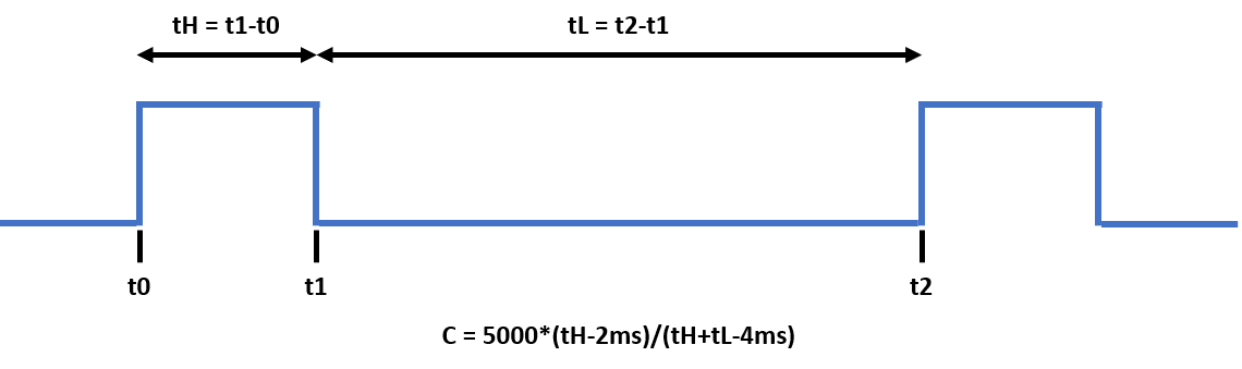
- tH: Time the PWM signal is high during one cycle.
- tL: Time the PWM signal is low during one cycle.
Because the Arduino, ESP8266 and ESP32 microcontroller can not measure a time range, we have to use the millis() function that returns the number of milliseconds passed since the microcontroller board began running the current program. Based on these timestamps when the PWM signal shows a rising or falling edge we can calculate the time ranges as follows:
- tH = t1-t0
- tL = t2-t1
The CO2 concentration is now calculated C = 5000*(tH-2ms)/(tH+tL-4ms).
MH-Z14A Pinout
In the datasheet, you find the following pinout if you look from the top on the MH-Z14A.
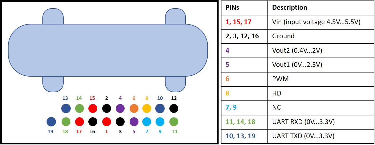
The connection between the MH-Z14A and different Arduino, ESP8266 and ESP32 microcontroller is shown in the next chapter of this article.
From the following table, you see all electronic components that I use for this tutorial. I get commissions for purchases made through links in this table.
| Component | Amazon Link | AliExpress Link |
|---|---|---|
| Arduino Nano | Amazon | AliExpress |
| Arduino Pro Mini | Amazon | AliExpress |
| Arduino Uno | Amazon | AliExpress |
| Arduino Mega | Amazon | AliExpress |
| ESP32 ESP-WROOM-32 | Amazon | AliExpress |
| ESP8266 NodeMCU | Amazon | AliExpress |
| ESP8266 WeMos D1 Mini | Amazon | AliExpress |
| MH-Z14A CO2 Sensor | Amazon | AliExpress |
Building a CO2 Alarm with the MH-Z14A
Now we want to build our CO2 alarm with the MH-Z14A and different Arduino, ESP8266 and ESP32 microcontroller boards. Our CO2 alarm should measure the CO2 concentration in the room every minute and plot the data to the serial plotter. Also, we want to use all three options to read the CO2 concentration and compare the different options to find out what the best option is regarding the stability and accuracy.
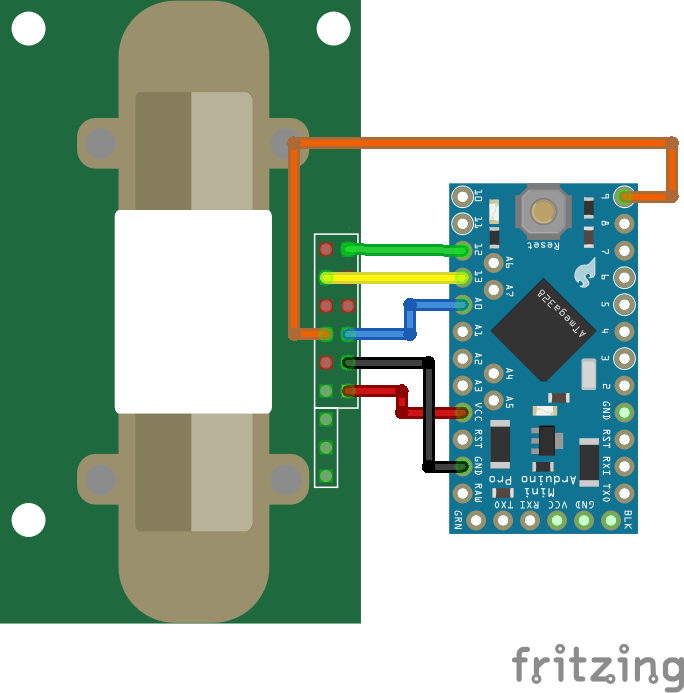
Wiring between MH-Z14A and different Microcontroller
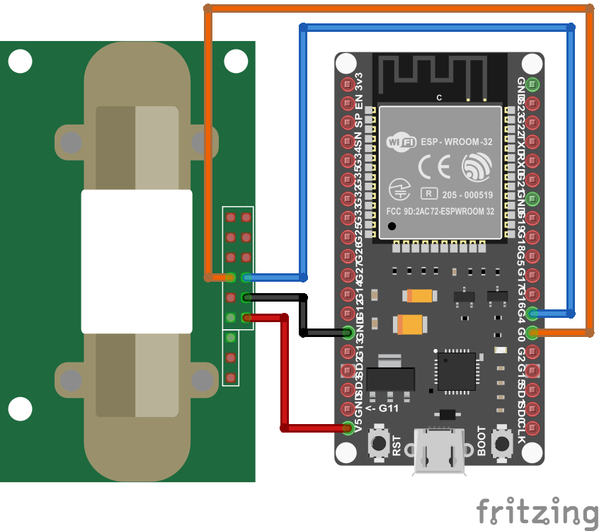
First, we have to connect the MH-Z14A to our microcontroller. The following pictures show the wiring between the CO2 sensor and different Arduino, ESP8266 and ESP 32 microcontroller boards.
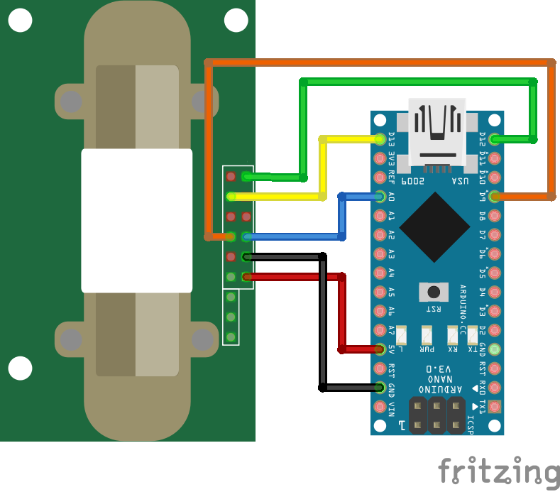
For more information about the Arduino Nano, visit the Arduino Nano Tutorial.
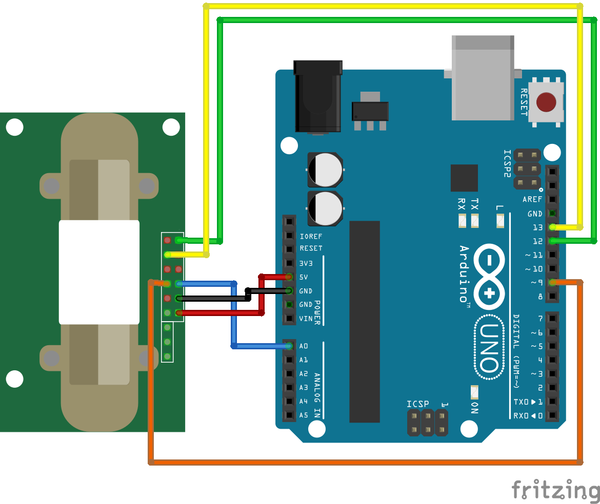
For more information about the Arduino Uno, visit the Arduino Uno Tutorial.
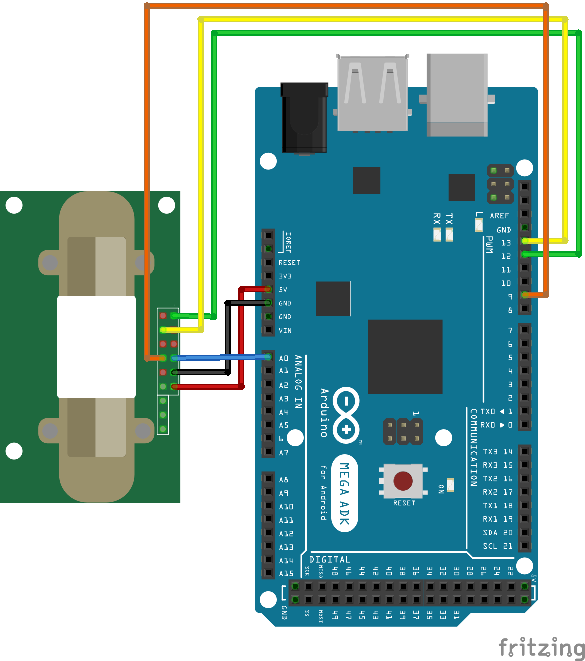
For more information about the Arduino Mega, visit the Arduino Mega Tutorial.
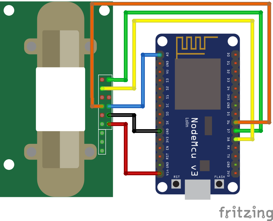
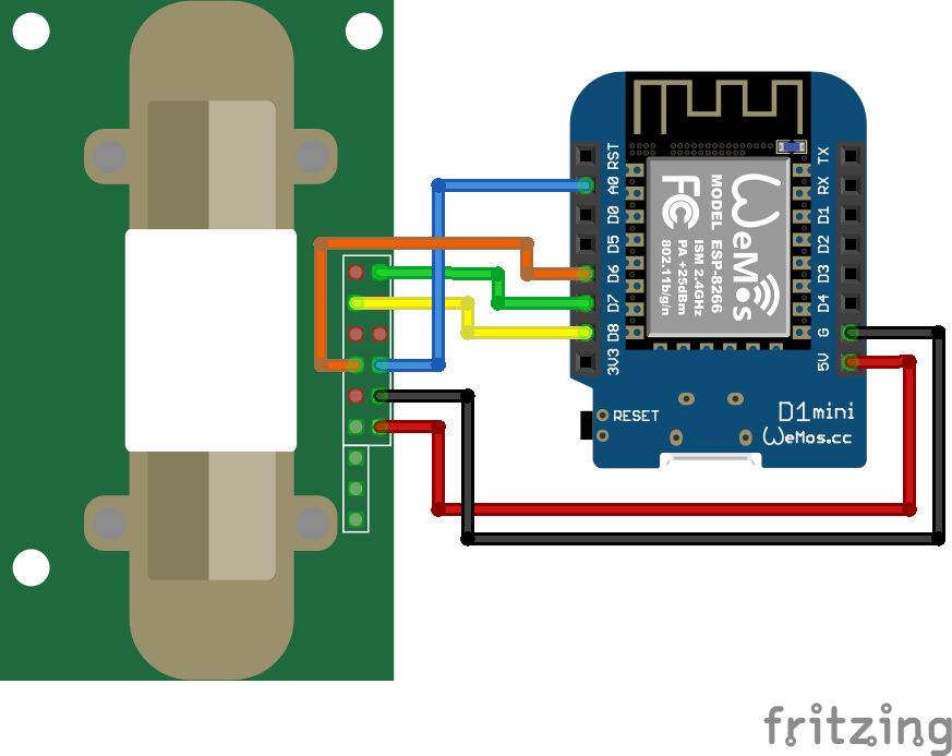
For more information about the ESP8266 WeMos D1 Mini, visit the ESP8266 WeMos D1 Mini Tutorial.
Arduino Program Code for CO2 Alarm with the MH-Z14A
After the wiring, we want to create the program script. Most of the program script is independent on the microcontroller, but because there are some small differences, I created a program script individually for the Arduino, ESP8266 and ESP32.
#include <SoftwareSerial.h>
SoftwareSerial SerialCom(13, 12); // RX, TX

// analog interface
const int analogPin = A0;

// PWM interface
const int pwmPin = 9;

void setup() {
  SerialCom.begin(9600);
  pinMode(pwmPin, INPUT_PULLUP);

  delay(180000); // preheat the CO2 sensor for 3 minutes

  Serial.begin(115200);
  Serial.println("Analog:,UART:,PWM:");
}

void loop() {
  int ppm_analog = get_analog();
  int ppm_uart = gas_concentration_uart();
  int ppm_PWM = gas_concentration_PWM();

  Serial.print(ppm_analog);
  Serial.print(",");
  Serial.print(ppm_uart);
  Serial.print(",");
  Serial.println(ppm_PWM);

  delay(60000); // sleep for 1 minute
}


int get_analog() {
  float v = analogRead(analogPin) * 5.0 / 1023.0;
  int gas_concentration = int((v) * (5000/2));

  return gas_concentration;
}


int gas_concentration_uart() {
  byte addArray[] = {0xFF, 0x01, 0x86, 0x00, 0x00, 0x00, 0x00, 0x00, 0x79};
  char dataValue[9];

  SerialCom.write(addArray, 9);
  SerialCom.readBytes(dataValue, 9);

  int resHigh = (int) dataValue[2];
  int resLow  = (int) dataValue[3];
  int ppm_uart = (resHigh*256)+resLow;

  return ppm_uart;
}


int gas_concentration_PWM() {
  while (digitalRead(pwmPin) == LOW) {};
  long t0 = millis();
  while (digitalRead(pwmPin) == HIGH) {};
  long t1 = millis();
  while (digitalRead(pwmPin) == LOW) {};
  long t2 = millis();
  long tH = t1-t0;
  long tL = t2-t1;
  long ppm = 5000L * (tH - 2) / (tH + tL - 4);
  while (digitalRead(pwmPin) == HIGH) {};
  delay(10);

  return int(ppm);
}#include <SoftwareSerial.h>
SoftwareSerial SerialCom(D8, D7); // RX, TX
// analog interface
const int analogPin = A0;
// PWM interface
const int pwmPin = D6;
void setup() {
SerialCom.begin(9600);
pinMode(pwmPin, INPUT_PULLUP);
delay(180000); // preheat the CO2 sensor for 3 minutes
Serial.begin(115200);
Serial.println("Analog:,UART:,PWM:");
}
void loop() {
int ppm_analog = get_analog();
int ppm_uart = gas_concentration_uart();
int ppm_PWM = gas_concentration_PWM();
Serial.print(ppm_analog);
Serial.print(",");
Serial.print(ppm_uart);
Serial.print(",");
Serial.println(ppm_PWM);
delay(60000); // sleep for 1 minute
}
int get_analog() {
float v = analogRead(analogPin) * 3.3 / 1023.0;
int gas_concentration = int((v) * (5000/2));
return gas_concentration;
}
int gas_concentration_uart() {
byte addArray[] = {0xFF, 0x01, 0x86, 0x00, 0x00, 0x00, 0x00, 0x00, 0x79};
char dataValue[9];
SerialCom.write(addArray, 9);
SerialCom.readBytes(dataValue, 9);
int resHigh = (int) dataValue[2];
int resLow = (int) dataValue[3];
int ppm_uart = (resHigh*256)+resLow;
return ppm_uart;
}
int gas_concentration_PWM() {
while (digitalRead(pwmPin) == LOW) {};
long t0 = millis();
while (digitalRead(pwmPin) == HIGH) {};
long t1 = millis();
while (digitalRead(pwmPin) == LOW) {};
long t2 = millis();
long th = t1-t0;
long tl = t2-t1;
long ppm = 5000L * (th - 2) / (th + tl - 4);
while (digitalRead(pwmPin) == HIGH) {};
delay(10);
return int(ppm);
}// analog interface
const int analogPin = 4;
// PWM interface
const int pwmPin = 0;
void setup() {
pinMode(pwmPin, INPUT_PULLUP);
delay(180000); // preheat the CO2 sensor for 3 minutes
Serial.begin(115200);
Serial.println("Analog:,PWM:");
}
void loop() {
int ppm_analog = get_analog();
int ppm_PWM = gas_concentration_PWM();
Serial.print(ppm_analog);
Serial.print(",");
Serial.println(ppm_PWM);
delay(60000); // sleep for 1 minute
}
int get_analog() {
float v = analogRead(analogPin) * 3.3 / 4095.0;
int gas_concentration = int((v) * (5000/2));
return gas_concentration;
}
int gas_concentration_PWM() {
while (digitalRead(pwmPin) == LOW) {};
long t0 = millis();
while (digitalRead(pwmPin) == HIGH) {};
long t1 = millis();
while (digitalRead(pwmPin) == LOW) {};
long t2 = millis();
long th = t1-t0;
long tl = t2-t1;
long ppm = 5000L * (th - 2) / (th + tl - 4);
while (digitalRead(pwmPin) == HIGH) {};
delay(10);
return int(ppm);
}In the first part of the program code, we define variables and the configurations for the communication interface between the microcontroller and the CO2 sensor.
The following variables are defined during the start of the program script:
- Pins for the UART serial communication: SerialCom
- Analog pin: analogPin
- Digital pin for the PWM interface: pwmPin
For the Arduino and ESP8266 program code, we define the software serial for the UART interface. We cannot use the standard interface, because the standard interface is used for the USB communication between the microcontroller and the PC, to send the measurements via the USB cable to the Arduino IDE.
For the ESP32 you cannot use the software serial, because the ESP32 has in total 3 UART interfaces that you can use. But from the program script, you see that I did not define the UART interface. The reason is, that I get a lot of resets when I tried to include the UART interface. I did not find the reason for these resets and I tried all three UART interfaces, but nothing worked. When I deleted the UART interface, everything runs smoothly. If you get the UART interface running for the ESP32, let me know how you achieved this in the comment section.
In the setup function we start the software serial communication with a baud rate of 9600, that is specified in the datasheet of the MH-Z14A. Also, we set the pin for the PWM signal as input and use the internal pullup resistor of the microcontroller.
Because the CO2 sensor needs time to heat up the IR lamp, we create a delay of 3 minutes.
After the delay we set the baud rate of the serial communication via USB to the PC to 115200 and print our table header that contains our three measurement interfaces for the Arduino and ESP8266, and two interfaces for the ESP32.
In the loop function we read the CO2 concentration from every function that you can find under the loop function. In each function, we implement the method that is described in the interface chapter. If you have any questions regarding the functions to read the CO2 concentration, please ask your question in the comment section below.
After we got all our CO2 measurements, we write the values of the CO2 concentration to the serial output and wait for 1 minute before we run the loop function all over again to read the new sensor values of the MH-Z14A.
Microcontroller Datasheet eBook
The 35 pages Microcontroller Datasheet Playbook contains the most useful information of 14 Arduino, ESP8266 and ESP32 microcontroller boards.
Key findings building the CO2 Alarm with the MH-Z14A
In the last chapter of this article, I want to discuss my key findings using different microcontroller when I build my CO2 Alarm with the MH-Z14A.
Key findings using the Arduino with the MH-Z14A
The following picture shows my measurements with the Arduino Uno, visualized with the serial plotter of the Arduino IDE. The MH-Z14A was not recalibrated during this measurement. The difference after the recalibration in shown in the next sub-chapter.
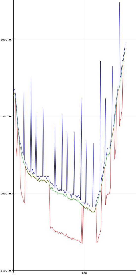
Using the analog interface of the MH-Z14A with an Arduino microcontroller (blue line)
If you see the analog values in the serial plotter, you directly notice the higher outliers that seems to occur on a regular basis. For a stable and valid measurement, the outliers are a big problem, because our alarm would start when an outlier exceeds a predefined alarm value.
Using the UART interface of the MH-Z14A with an Arduino microcontroller (red line)
Using the UART communication to receive the CO2 values from the MH-Z14A causes similar problems like the analog interface. We can see that the UART sensor values crack down and are running for time parallel to the PWM interface before they go up again. This behavior seems to be unregular and prevents the UART interface for being selected for the CO2 alarm.
Using the PWM interface of the MH-Z14A with an Arduino microcontroller (green line)
The PWM interface is the only one that has no outliers and can therefore be used for our CO2 alarm. Most of the time the PWM values are also validated by the CO2 concentration from the UART interface.
Key findings using the Arduino with the MH-Z14A after the recalibration
Maybe you saw that the sensor values in the last chapter were too high (between 1700ppm and 3200ppm) for being the actual CO2 concentration in my office.
As a recap, we defined that a well-ventilated room has a CO2 concentration under 800ppm (our warning trigger) and should be under 1000ppm (our alarm trigger).
Therefore we need to recalibrate the MH-Z14A by connecting pin 8 (HD) of the MH-Z14A with ground of your microcontroller for 7 to 10 seconds. The following picture shows you the CO2 measurement with my Arduino Uno after the recalibration.
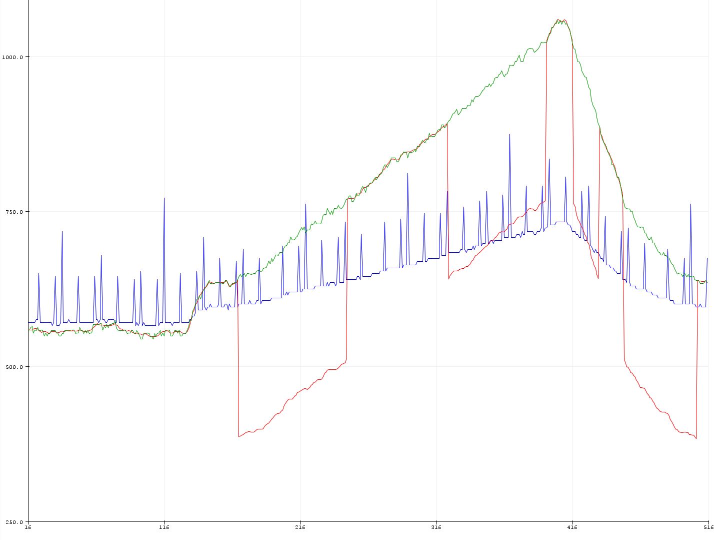
Now my CO2 concentration is around 600ppm when my office door is open, and the window is closed. When I close the door (I have a small office room) the CO2 concentration rises and exceeds the threshold of 800ppm and 1000ppm. At the end, I opened the window, and you see that the CO2 concentration is reduced by the fresh air.
The recalibration does not fix the misleading behavior of the analog and UART interface.
Key findings using the ESP8266 with the MH-Z14A
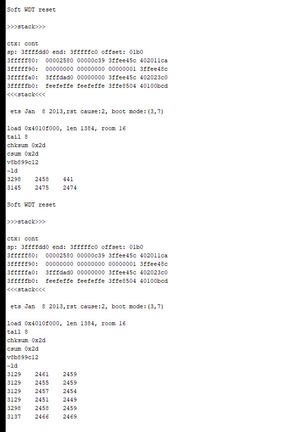
The key finding using the ESP8266 with the MH-Z14A is that I did not get this combination running. I used different ESP8266 microcontroller and tried every measurement interface separately. But I always got the same error code that you see in the following picture.
Key findings using the ESP32 with the MH-Z14A
When I used the ESP32 with the MH-Z14A I got problems with the UART interface that results in permanent restart of the ESP32. For this reason, I only used the analog and PWM interface to receive the CO2 concentration. Note that all sensor values are recorded before the recalibration.
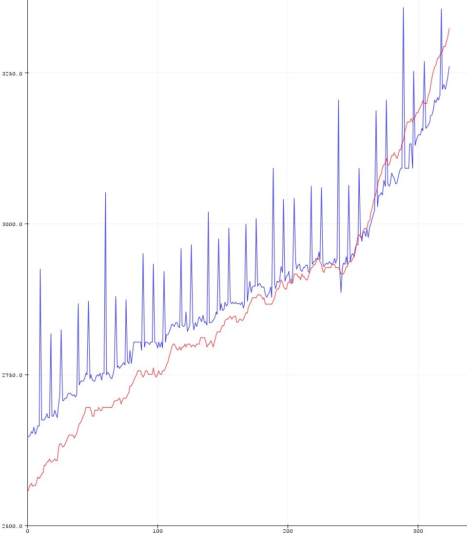
Using the analog interface of the MH-Z14A with an ESP32 microcontroller (blue line)
The ESP32 analog interface show the exact same outlier behavior as the Arduino. We get higher CO2 concentrations on a regular basis.
Using the PWM interface of the MH-Z14A with an ESP32 microcontroller (red line)
The PWM interface shows valid sensor values without any outliers. Therefore, I would recommend using the PWM interface of the MH-Z14A when you use an ESP32 microcontroller.
Conclusion building a CO2 Alarm with the MH-Z14A
The following points summarizes all my learnings during the creation of this article.
- Put your MH-Z14A CO2 sensor in the environment where you want to measure the CO2 concentration for at least 24h.
- Using the PWM interface will get you valid measurements of the CO2 concentration.
- Recalibrate the MH-Z14A by connecting pin 8 (HD) with ground for 10 seconds.
- If you build a system without using a Wi-Fi connection, use an Arduino microcontroller and if you want to build an IoT CO2 measurement sensor that sends the CO2 values to a central logger, use the ESP32 but no ESP8266.
If you have any questions regarding this article, feel free to ask your questions in the following comment section and I will answer them as soon as possible.

Dear Diyi0t,
I looked at your nodemcu wiring and thought. Hmmm… this would not work for me, as the Vin pin is NOT on 5V. That’s the VU Pin.
When I read that you did not manage to get nodemcu work, this might be the reason.
I will try tomorrow if I am right. Before that, thanks a lot, I found your tutorial REALLY interesting.
Best,
Wolfgang
Are you still watching this space? I fixed your esp8266 program. It needs a delay(1) in each of the pwm waiting loops. I cannot tell you WHY it works, but this avoids the crash you and I were experiencing.
I found your tutorial hugely helpful.
Thanks to you!
Wolfgang