TCRT5000 Line Tracking Module for Arduino, ESP8266 and ESP32
The TCRT5000 Line Tracking Module is an infrared distance module that is most used for robot applications like a line following robot, product line decoder or other robot projects.
In this tutorial you learn the pinout and schematic of two different TCRT5000 line tracking modules.
At the end of the tutorial, you learn how to build a line decoder that can also detect objects.
Table of Contents
TCRT5000 Module Technical Datasheet
The following table shows the technical specifications for the TCRT5000 module.
| Operation Voltage | 3V…5V DC |
| Emitter Wavelength | 950 nm |
| Peak Operating Distance | 2.5 mm |
The TCRT5000 module has an operation voltage between 3V and 5V that is perfect for all Arduino, ESP8266 and ESP32 microcontroller boards. The wavelength of the emitter LED is 950 nm that is on the top end of the infrared electromagnetic spectrum.
The peak operation distance is important for your setup in a robot for example and defines the distance between the sensor and the surface that reflects the infrared radiation. The peak operation distance of the TCRT5000 is 2.5 mm. The following picture, that you find also in the datasheet of Vishay Semiconductors shows the relative collector current in dependence of the operation distance.
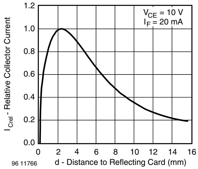
The relative collector current defines the strength of the received infrared signals and is dependent from the amount of IR that is reflected by a surface. Dependent of the color, material and texture of the surface, the reflectance of the surface differs and therefore the relative collector current.
From the chart you see the distance between the TCRT5000 module, and the surface should be greater than 1mm but not higher than 6mm to increase the relative collector current.
TCRT5000 Module Pinout and Electronic Components
There are two different TCRT5000 line tracking modules on the market. The major difference is that one module has an analog output that the other module does not have.
- The KY-033 line tracking module has no analog output.
The following picture shows the pinout and the electronic components of the two different modules.
The TCRT5000 modules consists of the following electronic parts:
- 3 to 4 output pins that connect the TCRT5000 module to a microcontroller, like the Arduino, ESP8266 or ESP32.
- A0 (not for the KY-033): Analog pin to transfer an analog signal.
- GND/G: Ground to connect the tracking sensor to ground with the microcontroller.
- VCC/V+: Pin for the 3.3V or 5V operation voltage regarding to the technical datasheet.
- D0/S: Digital output based on a predefined threshold through the potentiometer and the operation voltage of the microcontroller.
- Potentiometer to define a threshold for the digital output pin.
- 2 LEDs to indicate that the module is operating (LED1) and to indicate the status of the digital pin (LED2). The KY-033 has only one red LED that shows the status of the digital output.
- Multiple resistors to prevent LEDs for too high voltages and to operate as voltage dividers.
- The TCRT5000 module with analog output has to capacitors to increase the voltage stability.
- LM393 dual comparator to compare the signal created by the IR receiver with the predefined value through the potentiometer and to control the status of the LED that indicates the status of the digital output.
- TCRT5000 reflective IR sensors
- Blue LED: emission of infrared radiation
- Black part is an infrared receiver and with the black surface the daylight is blocked.
Schematic of the TCRT5000 Module with Analog Output
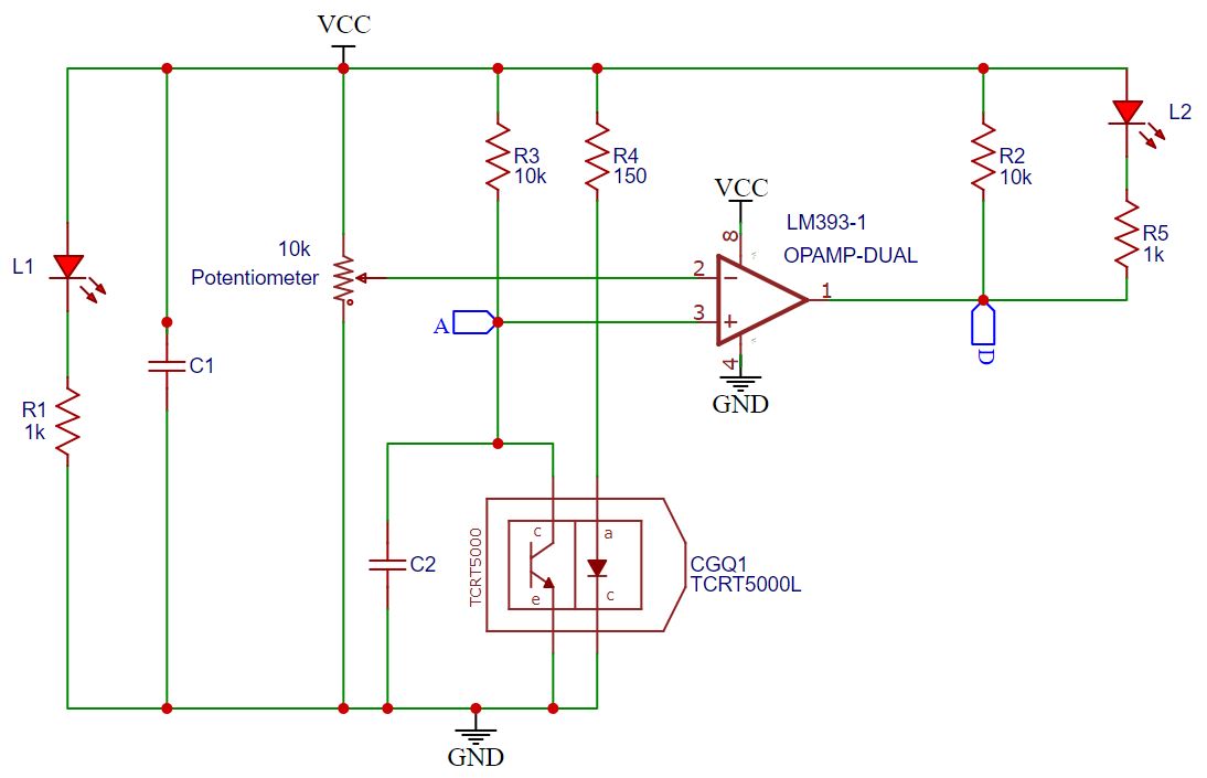
To understand the functionality of the TCRT5000 module with analog output, we have to take a closer look into the schematic of the PCB that shows us how the electronic components are connected. The following picture shows the schematic of the TCRT5000 module with analog output.
The module uses only one of the two comparators of the LM393 dual comparator. The output of the LM393 is numbered as 1 and the input 2 and 3. I use them as reference points in the following description of the schematic.
The TCRT5000 consists of two electronic parts that are also shown in the schematic:
- Infrared receiver with the black surface is shown as transistor.
- Infrared diode (blue LED) that emits the infrared radiation is shown as LED.
On the top of the schematic, we see that if VCC and ground is connected, the circuit over the resistor R1 (1kΩ) and LED L1 is closed. Therefore, LED L1 shows that the line tracking module is operating.
The capacitor C1 is also connected between VCC and GND to stabilize the operation voltage and would not be necessary if you use a stable power supply like the Arduino, ESP8266 or ESP32 microcontroller board with 3.3V or 5V voltage regulator.
The potentiometer (10kΩ) acts like an adjustable voltage divider and the output of the potentiometer is the reference voltage of the comparator (2).
The input voltage of the LM393 comparator (3) is the output of the voltage divider that is also the analog output (A) of the TCRT5000 PCB. This voltage divider is created by the resistor R3 (10kΩ) and the transistor of the TCRT5000. The capacitor C2 stabilizes the lower part of the voltage divider over the transistor.
If the module has a valid power supply, the infrared diode that is protected by resistor R4 (150Ω) against too high voltages starts emitting IR.
The output of the LM393 dual comparator (1) is connected to the digital output of the TCRT5000 line tracking module (D) and connected to the circuit part with resistor R2 (10kΩ) as well as LED (L2) and resistor R5 (1kΩ).
Schematic of the KY-033 TCRT5000 Module
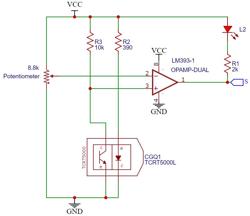
Compared to the TCRT5000 module with analog output the KY-033 module is a subpart and therefore easy to understand. The following picture shows the schematic of the KY-033 TCRT5000 module.
The KY-033 module uses only one of the two comparators of the LM393. The output of the LM393 dual comparator is numbered as 1 and the input 2 and 3. I use them as reference points in the following description of the schematic.
The TCRT5000 consists of two electronic parts that are also shown in the schematic:
- Infrared receiver with the black surface is shown as transistor.
- Infrared diode (blue LED) that emits the infrared radiation is shown as LED.
The potentiometer (8.8kΩ) acts like an adjustable voltage divider and the output of the potentiometer is the reference voltage of the comparator (2).
The input voltage of the LM393 comparator (3) is the output of the voltage divider that is created by the resistor R3 (10kΩ) and the transistor of the TCRT5000.
If the module has a valid power supply, the infrared diode that is protected by resistor R4 (390Ω) against too high voltages starts emitting IR.
The output of the LM393 dual comparator (1) is connected to the digital output of the TCRT5000 line tracking module (S) and connected to the circuit part with LED (L2) and resistor R1 (2kΩ).
The KY-033 TCRT5000 module has no analog output, no capacitors, and no LED to indicate a valid power supply.
Functionality of the TCRT5000 Module
After we know the schematic of the TCRT5000 modules, the functionality is not hard to understand. For the functionality, it is important to know that higher infrared radiation results in a lower resistance of the infrared receiver and therefore in a higher voltage drop across the IR receiver. You can see this dependence also from the following picture, that you find in the datasheet of the TCRT5000.
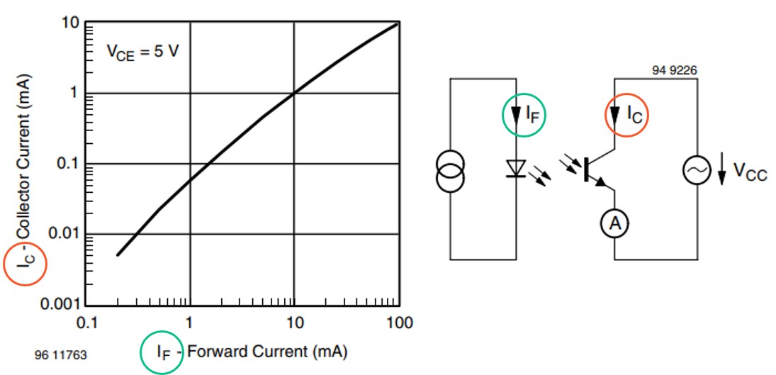
If the TCRT5000 module is powered, LED (L1) lights up if you have the module with the analog output and the infrared diode (blue LED) emits the infrared radiation. Depending on the coefficient of reflection and the distance of the surface that reflects the infrared radiation, the resistance of the infrared receiver is higher or lower.
The changing resistance of the IR receiver influences the output voltage of the voltage divider (and the analog output of the TCRT5000 module) with resistor (R4, R2) and the IR receiver: The higher the received IR, the higher the voltage drop across the IR receiver and therefore the analog output.
The potentiometer must be calibrated in a way that if there is no relevant infrared radiation, the reference voltage of the comparator (2) has to be higher than the input voltage (3) that equals the voltage drop across the IR receiver and the analog output. In this case, the output of the comparator (1) and therefore the digital output of the TCRT5000 module is equal to 0V. Because there is a potential difference between resistor R5 or R1 for the KY-003 and LED (L2), the LED is on.
If the received infrared radiation increases and for this reason also the analog output, the input voltage (3) of the LM393 exceeds the reference voltage (2), controlled by the potentiometer. Then the output of the LM393 dual comparator (1) switches from 0V to VCC and there is not longer a potential difference between resistor R5 or R1 for the KY-003 and LED (L2). In this case, the LED (L2) switches off.
The following pullet points summarize the functionality of the TCRT5000 module with analog output and the KY-003 module:
- If the received IR increases, the analog output also increases, if the module has an analog output.
- To increase or decrease the threshold of the digital output of the TCRT5000 module, adjust the potentiometer.
- If the threshold of the potentiometer is not exceeded, the digital output is LOW, and the LED (L2) is on.
- If the received IR increases further and the threshold of the potentiometer is exceeded, the digital output is HIGH, and the LED (L2) is off.
The following table gives you an overview of all components and parts that I used for this tutorial. I get commissions for purchases made through links in this table.
| Component | Amazon Link | AliExpress Link |
|---|---|---|
| Arduino Nano | Amazon | AliExpress |
| Arduino Pro Mini | Amazon | AliExpress |
| Arduino Uno | Amazon | AliExpress |
| Arduino Mega | Amazon | AliExpress |
| ESP32 ESP-WROOM-32 | Amazon | AliExpress |
| ESP8266 NodeMCU | Amazon | AliExpress |
| ESP8266 WeMos D1 Mini | Amazon | AliExpress |
| TCRT5000 Line Tracking Module in Sensor Kit | Amazon | - |
| TCRT5000 Line Tracking Module in Sensor Kit | - | AliExpress |
Wiring between TCRT5000 Modules and Microcontroller Boards
The input voltage of the TCRT5000 modules is between 3V and 5V and therefore we can use ESP8266 and ESP32 microcontroller with an operation voltage of 3.3V and all Arduino based boards with an operation voltage of 5V.
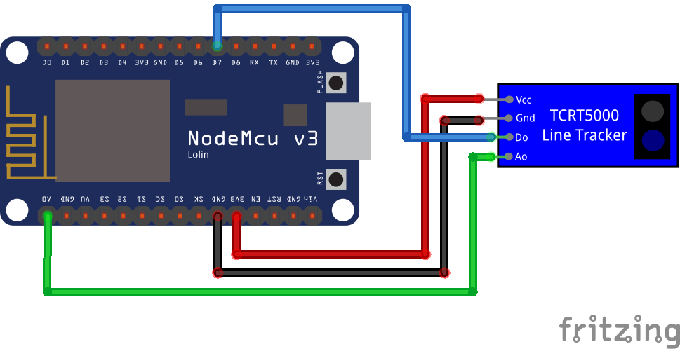
Wiring for TCRT5000 Module with Analog Output
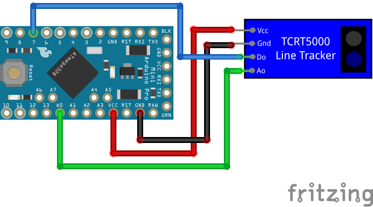
The following table and pictures show the wiring between the TCRT5000 module with analog output and different Arduino, ESP8266 and ESP32 boards.
| TCRT5000 module with analog output | Arduino | ESP8266 | ESP32 |
|---|---|---|---|
| VCC | 5V | 3V3 | 3V3 |
| GND | GND | GND | GND |
| D0 | 7 | D7 | 4 |
| A0 | A0 | A0 | 0 |
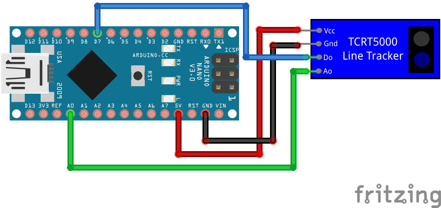
For more information about the Arduino Nano, visit the Arduino Nano Tutorial.
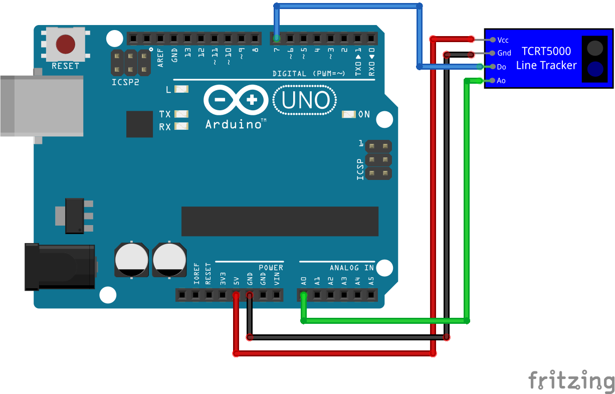
For more information about the Arduino Uno, visit the Arduino Uno Tutorial.

For more information about the Arduino Mega, visit the Arduino Mega Tutorial.
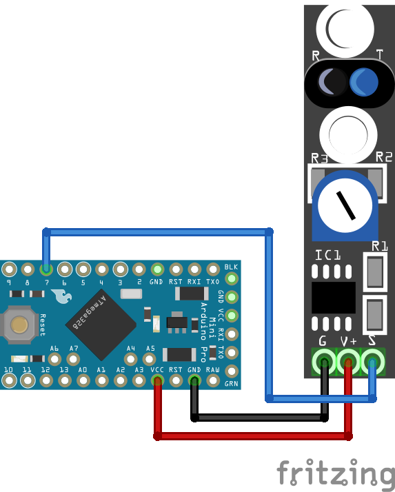
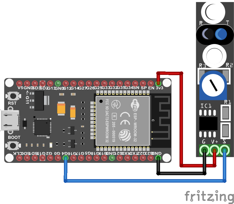
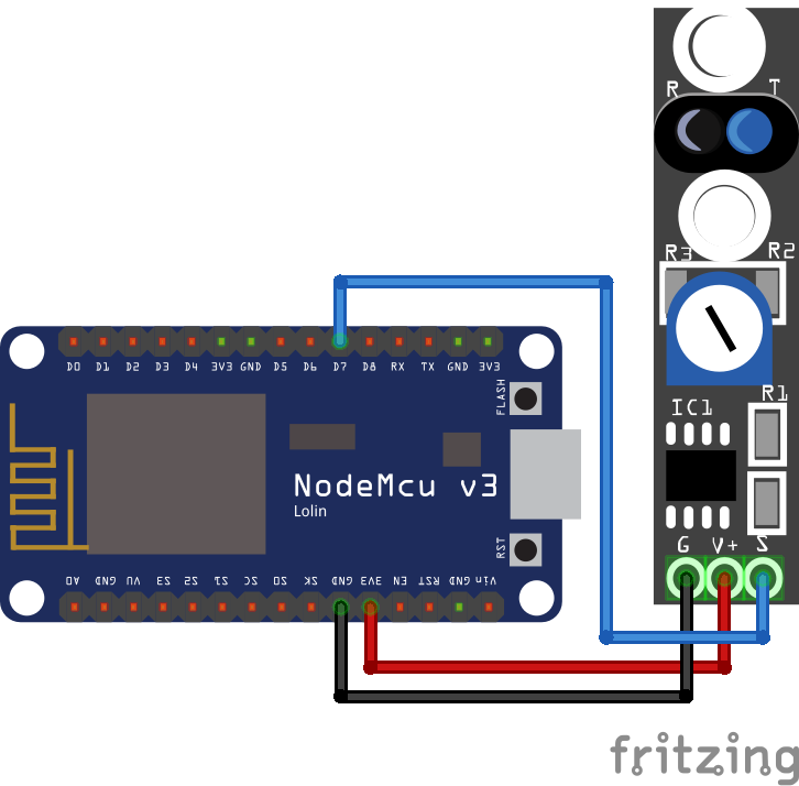
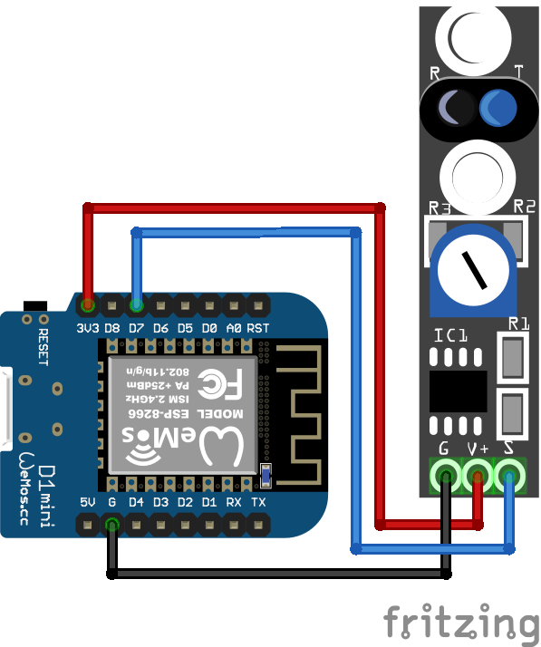
Wiring for KY-033 TCRT5000 Module
The following table and pictures show the wiring between the KY-033 TCRT5000 module and different Arduino, ESP8266 and ESP32 boards.
| TCRT5000 KY-033 module | Arduino | ESP8266 | ESP32 |
|---|---|---|---|
| V+ | 5V | 3V3 | 3V3 |
| G | GND | GND | GND |
| S | 7 | D7 | 4 |
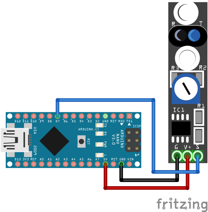
For more information about the Arduino Nano, visit the Arduino Nano Tutorial.
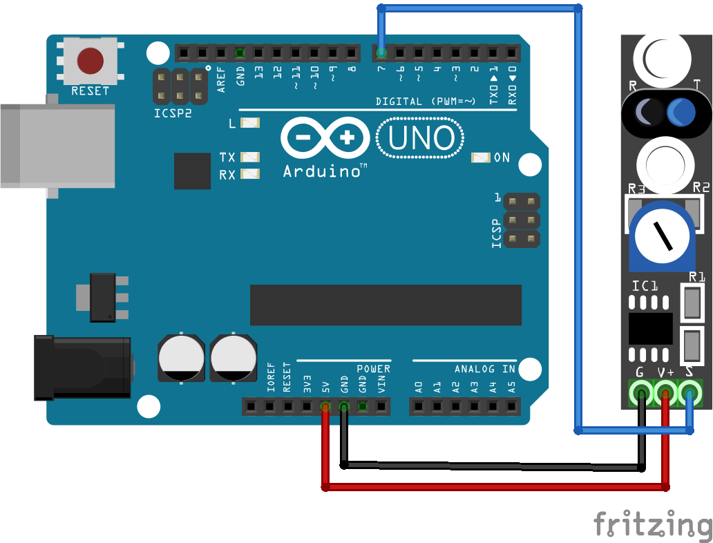
For more information about the Arduino Uno, visit the Arduino Uno Tutorial.
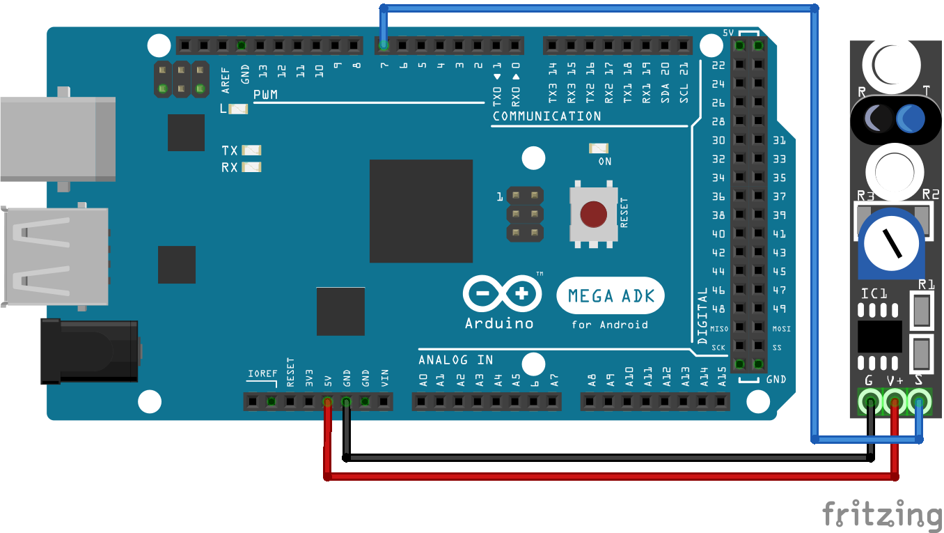
For more information about the Arduino Mega, visit the Arduino Mega Tutorial.
Microcontroller Datasheet eBook
The 35 pages Microcontroller Datasheet Playbook contains the most useful information of 14 Arduino, ESP8266 and ESP32 microcontroller boards.
Program Code to Build a Line Decoder
In our program example we detect objects in front of the sensor and the influence of different surfaces and surface colors that is used to build a line decoder that you see in many Arduino robot projects.
Because we use in this tutorial two different TCRT5000 module, I split the program example also in two subsections.
- Measure the influence of different surfaces and surface colors with the TCRT5000 module with analog output.
- Detect an object in front of the KY-033 module.
Influence of Different Surfaces on the Line Tracking Module
We use the TCRT5000 line tracking module with analog output to measure the difference between a white and a black surface. The following section shows the program code for the line tracking module.
					// for Arduino microcontroller
const int digital_pin = 7;
const int analog_pin = A0;

// for ESP8266 microcontroller
//const int digital_pin = D7;
//const int analog_pin = A0;

// for ESP32 microcontroller
//const int digital_pin = 4;
//const int analog_pin = 0;

void setup(){
  Serial.begin(9600);
  pinMode(digital_pin,INPUT);
}

void loop(){
  Serial.print("Analog Reading=");
  Serial.print(analogRead(analog_pin));
  Serial.print("\t Digital Reading=");
  Serial.println(digitalRead(digital_pin));
  delay(1000);
}
At the beginning of the program code, we define the digital and analog pins that connect your Arduino, ESP8266 or ESP32 microcontroller board with the TCRT5000 line tracking module via the analog output like you saw in the wiring chapter. Because the script is written for different microcontroller, you must comment out the two lines for your microcontroller and delete or comment the other lines. The default script is written for Arduino boards.
In the setup function, we set the baud rate to 9600 that has to be the same baud rate like in the serial monitor of the Arduino IDE and we define the digital pin as input, because we want to read the digital state of the TCRT5000 module. The analog pin is not defined as input.
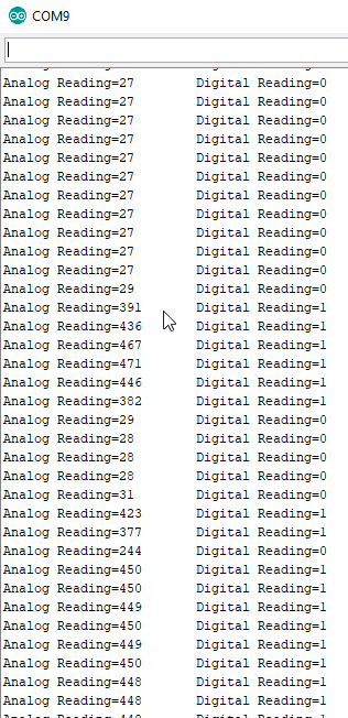
The loop function is super simple, because we only read the analog and digital value of the line tracking module and print the values to the serial monitor of the Arduino IDE. After a short delay of 1 second, the loop function starts all over again.
The following screenshot shows the output of the serial monitor and the video shows the result, measuring the difference between a white and a black surface.

By loading the video, you agree to YouTube's privacy policy.
Learn more
Object Detection with KY-033 TCRT5000 Line Tracking Module
The KY-033 TCRT5000 line tracking module does not have an analog output to measure a distance between the module and an object. But with the digital value and the distance threshold that can be adjusted with the potentiometer, we can build an object detector that is able to navigate a robot car through a parkour.
If an object gets in front of the module, we want to turn on the internal LED of the microcontroller board, but you could also activate a function that for example turns a robot car 90 degrees and check if there is still any object in front of the car.
The following sections shows the program code for the object detection with KY-033 TCRT5000 line tracking module.
					// for Arduino microcontroller
const int digital_pin = 7;
const int internal_LED = 13;

// for ESP8266 microcontroller
//const int digital_pin = D7;
//const int internal_LED = D0 ;

// for ESP32 microcontroller
//const int digital_pin = 4;
//const int internal_LED = 2;

void setup(){
  pinMode(digital_pin, INPUT);
  pinMode(internal_LED, OUTPUT);
}

void loop(){
  if(digitalRead(digital_pin) == HIGH){
    digitalWrite(internal_LED, LOW); //turn off the led
  }
  else{
    digitalWrite(internal_LED, HIGH); //turn on the led
  }
}
At the beginning of the program code, we define the pins that connect your Arduino, ESP8266 or ESP32 microcontroller board with the KY-033 TCRT5000 module, like you saw in the wiring chapter, but this time only with the digital connection. The internal LED is also connected via a digital pin to the microcontroller, that is defined in the top section of the script. Because the script is written for different microcontroller, you must comment out the two lines for your microcontroller and delete or comment the other lines. The default script is written for Arduino boards.
In the setup function, we define the digital pin that connects the microcontroller to the KY-033 module as input, because we want to read the digital state of the sensor module. The LED pin is defined as output since the internal LED is controlled by the microcontroller.
For the loop function, we create an if statement that reads the digital state of the KY-033 TCRT5000 module. If the state is HIGH, the internal LED tuns off and otherwise the internal LED is on.
The following video shows the result that the internal LED lights up, when the object is detected by the KY-033 TCRT5000 module.

By loading the video, you agree to YouTube's privacy policy.
Learn more
Do you have any further questions about the different TCRT5000 modules? Use the comment section below to ask your questions. If you plan to use a distance sensor for a DIY project, check out the article about the ultrasonic distance sensor, the infrared sensor in general and the HC-SR501 PIR motion sensor.




I just want to say thanks for this very imformative blogpost. Even when I use an easy ESP Home Installation the wiring and explanation was perfect.