HC-SR501 PIR Motion Sensor for Arduino, ESP8266 and ESP32
The HC-SR501 PIR Motion Sensor is an infrared sensor that is able to detect motions. In this tutorial, I show you how the functionality of the HC-SR501 with the help of the schematic of the PCB.
We discuss all three adjustment options before you see how to wire the HC-SR501 PIR Motion Sensor with different Arduino, ESP8266 and ESP32 microcontroller.
You also learn how to operate the HC-SR501 directly from 3.3V instead of greater than 5V.
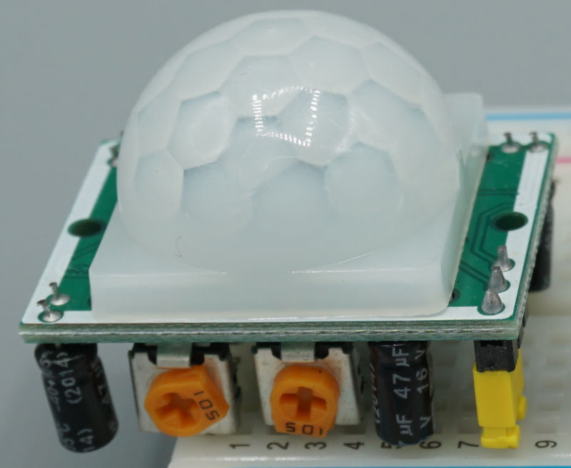
Table of Contents
Technical Datasheet of the HC-SR501 PIR Motion Sensor
The following table shows the technical details of the HC-SR501 PIR Motion Sensor.
| Input voltage | 5V…20V (but with a hack, we can use 3.3V) |
| Operating voltage | 3.3V |
| Quiescent current | 50 μA |
| Level output | HIGH 3.3 V / LOW 0 V |
| Initial stabilization time | 60s |
| Trigger | Single trigger (L) or Repeating trigger (H) |
| Delay time | 2.5s …5min |
| Measuring distance | 3m …7m |
| Measuring angle | < 110° cone angle |
The input voltage of the HC-SR501, regarding the datasheet, is between 5V and 20V. You might think that the motion sensor cannot be powered from an ESP8266 or ESP32 microcontroller. But in one of the next chapters, we take a deeper look in the schematic of the HC-SR501 and will see that the operating voltage is 3.3V and we can use a little trick to supply the HC-SR501 from an ESP8266 or ESP32.
The quiescent current of the HC-SR501 is around 50 μA and with this low power consumption also suitable for battery powered projects.
The output of the HC-SR501 PIR Motion Sensor is:
- HIGH (3.3V) when a movement is detected.
- LOW (0V) when no movement is detected.
If you start the motion sensor, you must wait for 60 seconds for an initial stabilization time to get accurate measurements. We will consider this initial stabilization time in the setup function of our Arduino program code.
The HC-SR501 has in total 3 adjustment options:
- Single trigger (Low) where several consecutive triggers are recognized as one trigger or repeating trigger (High) where every detected trigger is computed.
- Delay time that defines how long the output of the HC-SR501 stays HIGH after a motion is detected between 2.5 seconds and 5 minutes.
- Measuring distance between 3 meters and 7 meters.
The measuring angle of the HC-SR501 is 110° to be able to record movements in a wide angle in front of the sensor.
HC-SR501 PIR Motion Sensor Pinout
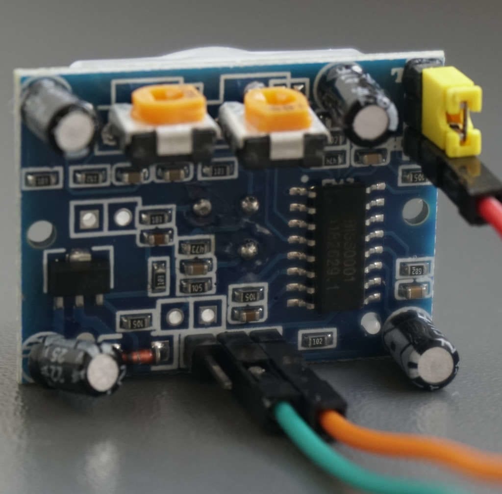
The following picture shows the bottom view of the HC-SR501 PIR Motion Sensor where we see all pins and adjustment potentiometers.
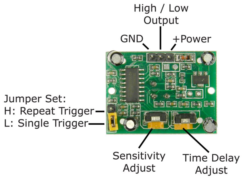
On the top, you see the 2 power and ground connection pins that connect the motion sensor with the power source, that is most of the time our Arduino, ESP8266 or ESP32 microcontroller. The pin in the middle is the digital output that can be HIGH if there is a motion detected or otherwise LOW.
On the left side there are the jumpers that define the trigger mode that we want to use. If you connect the upper pin with the middle pin, you have a repeating trigger (H) and if you connect the middle pin with the under pin, the HC-SR501 only recognizes single trigger (L).
For the sensitivity and time delay adjustment, you have two potentiometers on the bottom of the PIR motion sensor.
Schematic of the HC-SR501 PIR Motion Sensor
To understand the functionality of the HC-SR501 PIR Motion Sensor, we take a closer look at the schematic of the HC-SR501 PIR motion sensor. Because the HC-SR501 has a lot of components, we will focus on the main electrical components that are important to understand the functionality and the adjustments that can be made for the operation.
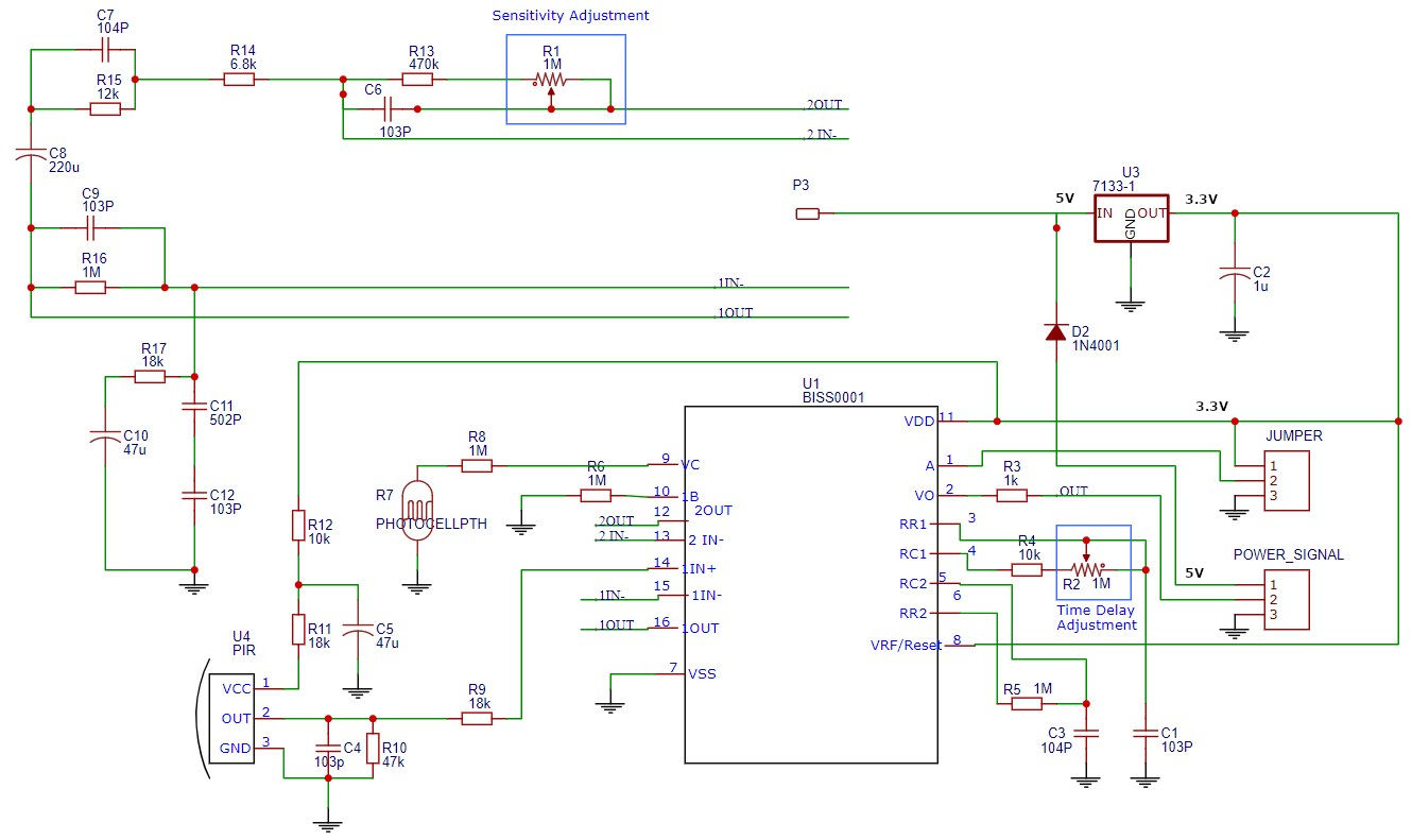
The following picture shows the schematic of the HC-SR501.
HC-SR501 Power Supply and Voltage Regulator
On the lower right side, you see a block called “POWER_SIGNAL”. This block has 3 pins that are our connection for the power supply and the digital output that we saw in the previous pinout chapter. The connection pins are the following:
| Pin in the Schematic | Pin on the PCB | Description |
|---|---|---|
| 1 | +Power | Positive DC power supply between 5V…20V |
| 2 | HIGH/LOW Output | Digital output (HIGH: 3.3V or LOW: 0V) |
| 3 | GND | Ground |
The positive pole of the DC power supply (1) is connected with the HT7133-1 LDO (Low Drop Out) voltage regulator. The last two digits of the HT7133 indicate that the output voltage is 3.3V. For this reason, the operation voltage of the HC-SR501 PIR Motion Sensor is 3.3V.
We see from the schematic, that the jumper connections, in the schematic “JUMPER”, are also connected to 3.3V rail with pin 1 and to ground with pin 3.
BISS0001 Micro Power PIR Motion Detector IC
The main functionality of the HC-SR501 module is provided by the BISS0001 Micro Power PIR Motion Detector IC. The following table shows the pins of the BISS0001 and a detailed description of the functionality of each pin.
| Pin Number | Symbol | Description |
|---|---|---|
| 1 | A | Trigger Selection and connected to the Trigger Selection Jumper. HIGH: the PIR motion sensor becomes re-triggerable. LOW: The HC-SR501 becomes non-re-triggerable. |
| 2 | V0 | Output pin and connected to the digital output of the HC-SR501 |
| 3 | RR1 | Output pulse width control that defines the time duration during which the output pin (Vo) remains high after triggering and is therefore connected to the potentiometer for the time delay adjustment. |
| 4 | RC1 | |
| 5 | RC2 | Trigger inhibit control that cannot be changed |
| 6 | RR2 | |
| 7 | VSS | Ground connection |
| 8 | VRF | Reset and voltage reference input that equals the 3.3V supply voltage |
| 9 | VCC | Trigger disable input can be connected to a photoresistor that the motions sensor is only active during the day or only at night. |
| 10 | IB | Op-amp input bias current setting |
| 11 | VDD | 3.3 supply voltage |
| 12 | 2OUT | 2nd stage Op-amp output and inverting input, that is connected to the potentiometer to adjust the sensing distance. |
| 13 | 2IN | |
| 14 | 1IN+ | 1st stage Op-amp non-inverting input that is connected to the IR electrodes |
| 15 | 1IN- | 1st stage Op-amp output and inverting input |
| 16 | 1OUT |
Different HC-SR501 Adjustment Options
In this subsection, we want to take a closer look at the three different adjustment options of the HC-SR501 PIR Motion Sensor:
- Distance adjustment
- Time delay adjustment
- Trigger selection
HC-SR501 Sensing Distance Adjustment
The HC-SR501 has a sensing distance between 3m and 7m. Via the onboard potentiometer, you can adjust the sensing distance. If the position of the potentiometer is most clockwise, the sensing distance is 7 meters. By rotating the potentiometer counterclockwise, you decrease the sensing distance down to 3 meters.
HC-SR501 Time Delay Adjustment
The time delay defines how long the output of the HC-SR501 stays HIGH after a motion is detected. You can adjust the time delay with the onboard potentiometer. The minimum (most counterclockwise position) setting is 3 seconds, and the maximum time delay is 5 minutes (most clockwise).
The setting of the time delay is only active when the trigger selection jumper is set to a single trigger (L). The next section discusses the trigger selection jumpers.
HC-SR501 Trigger Selection Jumper
The trigger modes are computed via the BISS0001 Micro Power PIR Motion Detector IC that you already know from the schematic. Pin A (1) of the BISS00001 controls the re-triggerable or non-re-triggerable mode.
- Pin A is connected to ground: The HC-SR501 becomes non-re-triggerable.
- Pin A is connected to the 3.3V supply voltage: the PIR motion sensor becomes re-triggerable.
Thus, we can select between the two trigger modes by selecting which pins we connect via the yellow jumper.
- Single trigger (L): The jumper connects pins 1 & 2, so that pin A of the BISS00001 is connected to ground.
As soon as a motion is detected by the motion sensor, the output of the HC-SR501 turns HIGH and stays high for the time that is configured by the time delay potentiometer. Any motion in this time delay is not considered. - Repeating trigger (H): The jumper connects pins 2 & 3, so that pin A of the BISS00001 is connected to 3.3V.
When a motion is detected, the output turns HIGH for the time that is configured by the time delay potentiometer like a single trigger but every motion during the time delay is detected and restarts the time delay.
In the next section, we discuss the functionality of the HC-SR501 PIR Motion Sensor where you also see a time series chart with the difference of both trigger selections.
Functionality of the HC-SR501 PIR Motion Sensor
The HC-SR501 PIR Motion Sensor has a white dome on the PCB that is a Fresnel lens to focus IR onto the sensing element. The sensing element on the HC-SR501 is a RE200B Pyroelectric Passive Infrared Sensor.
The motion sensor contains a positive and negative electrode, configured as balanced differential series opposed type so that the electrodes cancel each other out. For this reason, the PIR motion sensor detects changes in IR levels and not constant IR levels.
The onboard BISS0001 Micro Power PIR Motion Detector IC processes the signal of both electrodes and outputs a HIGH or LOW signal to the microcontroller. Because the output of the HC-SR501 is HIGH or LOW, you can use this PIR motion sensor module without any microcontroller by connecting the output of the HC-SR501 with the input of a relay to turn on a light or with the input of an active buzzer to create an alarm.
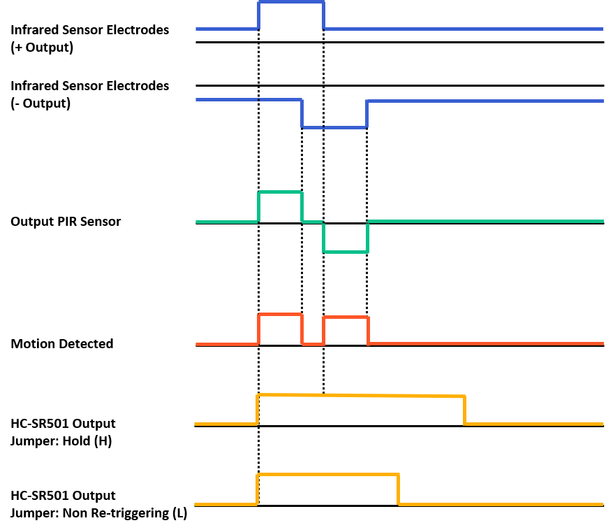
The following picture shows a time series of all relevant signals that are important for the functionality of the HC-SR501 PIR Motion Sensor.
Imagine you place the motion detection sensor in front of a door so that the sensor should recognize when someone passes this door.
The first two lines are the positive and negative electrodes of the IR sensor. Because either the left or the right sensor receives the infrared radiation of a person, passing the door, we have a short time delay between both electrodes that you see from the picture. In our case the positive electrode receives the IR before the negative electrode.
From the output of the PIR sensor, you see that both electrodes are connected to each other that they cancel each other out. You simply must add the positive and negative output of both electrodes and if the absolute amount of the detected IR signal is different, you get an output of the PIR sensor unequal to zero.
The BISS0001 Micro Power PIR Motion Detector calculates the absolute value of the PIR output and outputs a digital signal depending on the used HC-SR501 trigger selection jumper:
- If the trigger selection jumper is repeating trigger (H), you see that the second spike from the motion detected signal is recognized and increases the time that the digital output stays HIGH.
- If the trigger selection jumper is single trigger (L), only the initial spike of the motion detected signal is considered and therefore, the time that the HC-SR501 PIR motion sensor stays HIGH is lower compared to the hold jumper selection.
The following table gives you an overview of all components and parts that I used for this tutorial. I get commissions for purchases made through links in this table.
| Component | Amazon Link | AliExpress Link |
|---|---|---|
| Arduino Nano | Amazon | AliExpress |
| Arduino Pro Mini | Amazon | AliExpress |
| Arduino Uno | Amazon | AliExpress |
| Arduino Mega | Amazon | AliExpress |
| ESP32 ESP-WROOM-32 | Amazon | AliExpress |
| ESP8266 NodeMCU | Amazon | AliExpress |
| ESP8266 WeMos D1 Mini | Amazon | AliExpress |
| HC-SR501 PIR Motion Sensor in Sensor Kit | Amazon | - |
| HC-SR501 PIR Motion Sensor | - | AliExpress |
Wiring between HC-SR501 PIR Motion Sensor and Arduino Boards
The wiring between the HC-SR501 PIR Motion Sensor and different Arduino boards is shown in the following pictures. The digital output of the HC-SR501 is received via digital I/O pin 7 of the Arduino. We use the 5V operation voltage of the Arduino as power supply of the motion sensor.
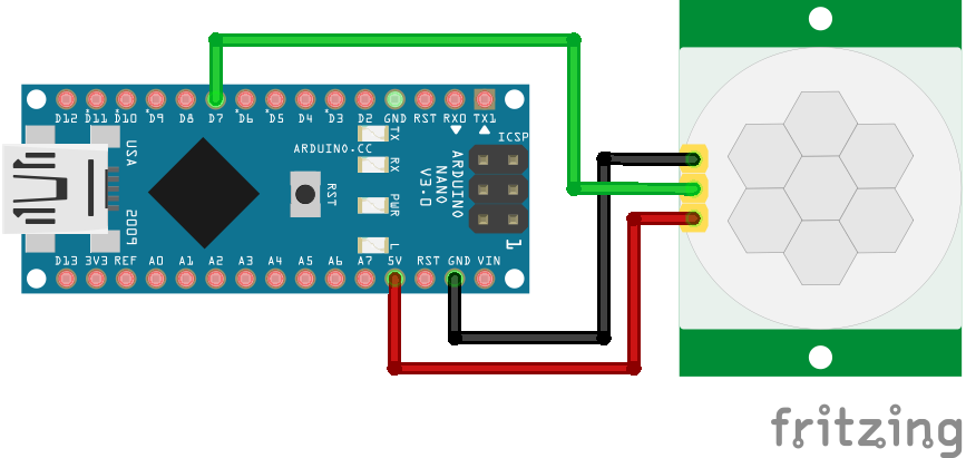
For more information about the Arduino Nano, visit the Arduino Nano Tutorial.

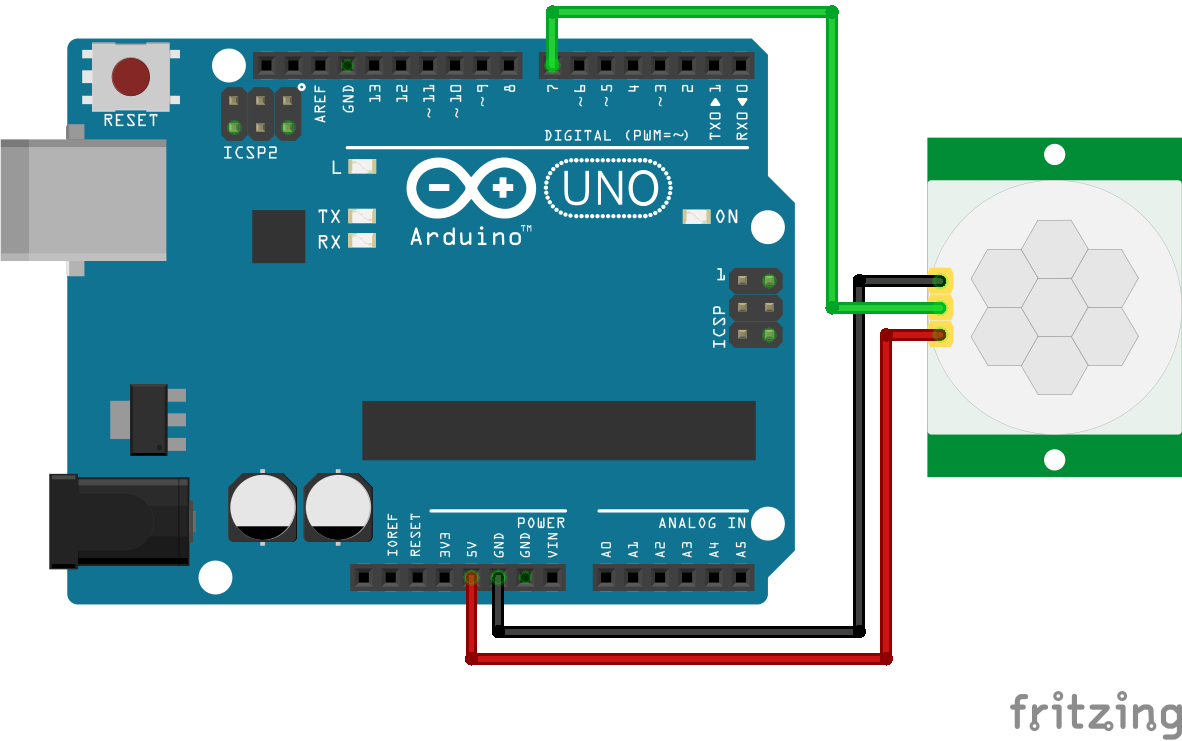
For more information about the Arduino Uno, visit the Arduino Uno Tutorial.
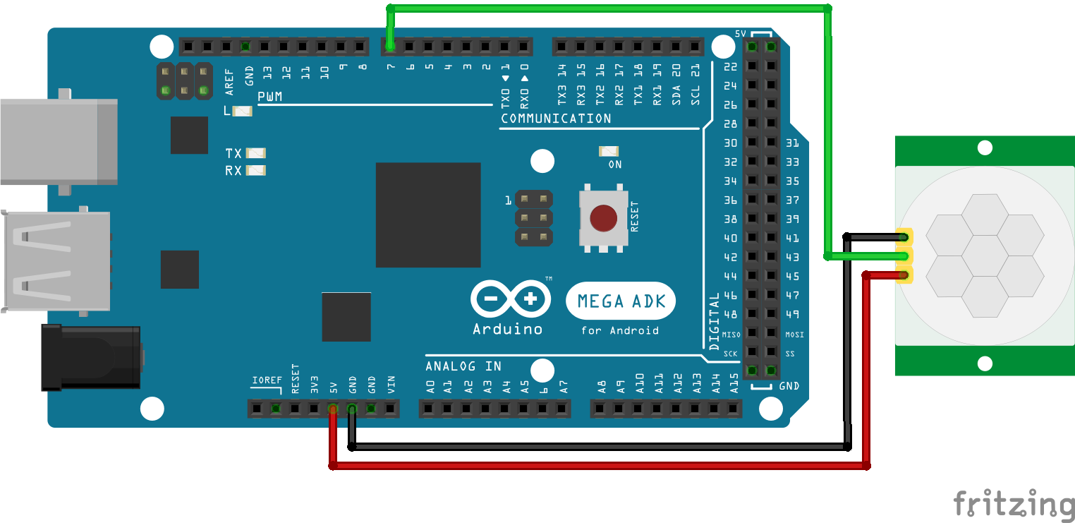
For more information about the Arduino Mega, visit the Arduino Mega Tutorial.
Microcontroller Datasheet eBook
The 35 pages Microcontroller Datasheet Playbook contains the most useful information of 14 Arduino, ESP8266 and ESP32 microcontroller boards.
How to use a 3.3V Power Supply for the HC-SR501?
From the technical datasheet of the HC-SR501, we know that the BISS0001 Micro Power PIR Motion Detector has an operation voltage of 3.3V and in the section of the schematic we saw that the higher input voltage is reduced to 3.3V via the HT7133-1 LDO voltage regulator.
Therefore, we only need some possibility to connect the power supply of the ESP8266 or ESP32 with the 3.3V rail of the HC-SR501. The following picture shows again the schematic of the HC-SR501 and if you take a closer look to the tree jumper connectors, you see that pin 1 of the jumpers is connected to the 3.3V rail.
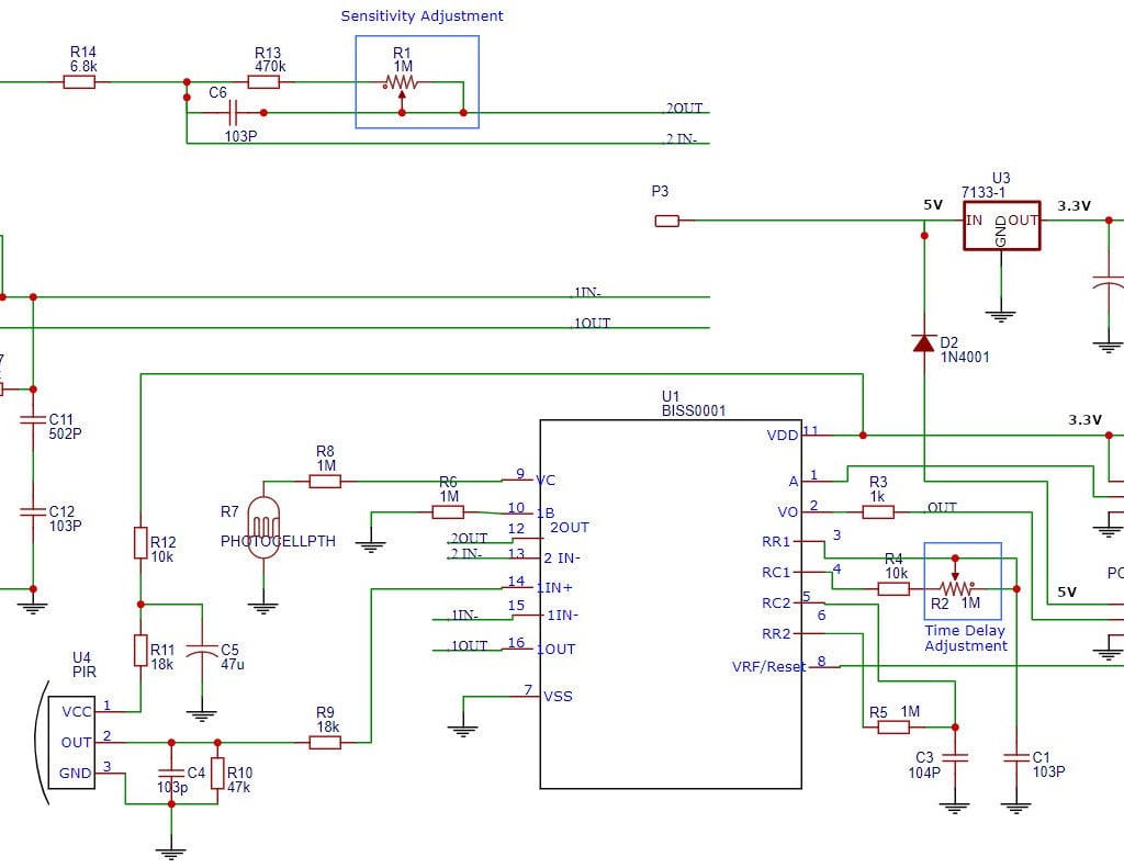
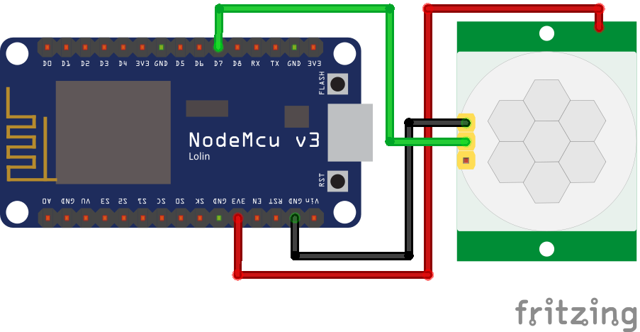
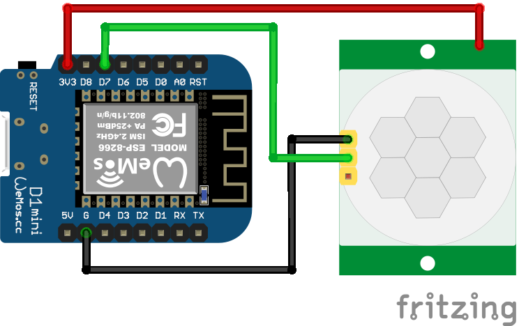
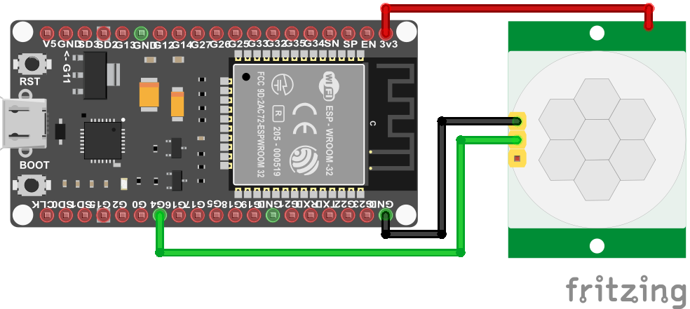
And this is our solution, we use pin 1 of the jumpers as positive pole for the DC supply voltage and the repeating trigger (L) mode that connects pins 2 and 3. The following photo shows the connections between the HC-SR501 PIR Motion Sensor and the ESP8266 or ESP32.
Wiring between HC-SR501 and ESP8266 / ESP32 Boards
The wiring between the HC-SR501 PIR Motion Sensor and the ESP8266 or ESP32 has a major difference compared to the wiring for the Arduino, because we do not use the standard pins for the power supply, but the jumper wire 1 that you saw in the previous chapter. The digital output of the HC-SR501 is received from digital pin D7 of the ESP8266 and from pin 4 of the ESP32. The following pictures show the wiring.
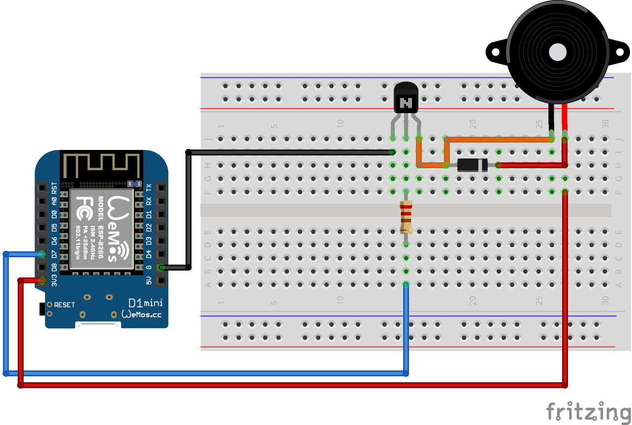
Program Code to Build a HC-SR501 Motion Alarm Detector
Now we want to use the HC-SR501 PIR Motion Sensor as motion alarm detector. You can use your favorite Arduino, ESP8266 or ESP32 microcontroller board for this project and use the wiring from the previous chapters.
The following sections shows the program code for the motion alarm detector.
					int inputPin = 7; // for Arduino microcontroller
//int inputPin = D7; // for ESP8266 microcontroller
//int inputPin = 4; // for ESP32 microcontroller

void setup() {
  pinMode(inputPin, INPUT);
  Serial.begin(9600);

  delay(60*1000);
}

void loop(){
  int val = digitalRead(inputPin);
  if (val == HIGH) {
    Serial.println("Motion detected!");
    }
  else {
    Serial.println("No Motion detected!");
    }

delay(10);
}
The program code is written for Arduino, ESP8266 and ESP32 microcontroller. For that reason, you only have to use one out of the first three lines of the program code that defines the connection pin where the microcontroller is connected to the HC-SR501. You can comment out or delete the other lines of code that does not match to your used microcontroller.
In the setup function we define the digital pin as input because we receive the motion signal from the sensor, and we set the baud rate to 9600 for the USB serial connection to read the data with the serial monitor of the Arduino IDE. We also add a delay of 60 seconds, because the HC-SR501 has an initial stabilization time.
The loop function starts with reading the digital value of the HC-SR501. Then we create a simple if-else statement to define that if the digital value of the motion alarm detector is high, we print that a motion is detected and if the digital value stays low, we print that no motion is detected.
In the end we wait for 10 milliseconds before we start the loop function all over again.

This is one of best and detailed guide on HC-SR501 in the net.
I would agree. This is the most comprehensive article a DIYer could wish for regarding this motion sensor. I am moving into a new house within the next month and have a mind to apply some home automation to it. This one will be a handy resource to me.
ok so far so good but how do i get it to talk to my Alexa enabled items to say “intruder alert”
Hello David, If you can find one of those “Alexa push button” modules ( now discontinued ) I think one of those could help you. But, otherwise it would be not an easy task. Good luck.