Active and Passive Buzzer for Arduino, ESP8266 and ESP32
In this tutorial you learn how active and passive buzzer work and the differences between both buzzers.
After we create a full circuit along with a NPN MOSFET and flyback diode and Arduino, ESP8266 or ESP32 microcontroller, we program a sound example for the active buzzer and a melody example for the passive buzzer.
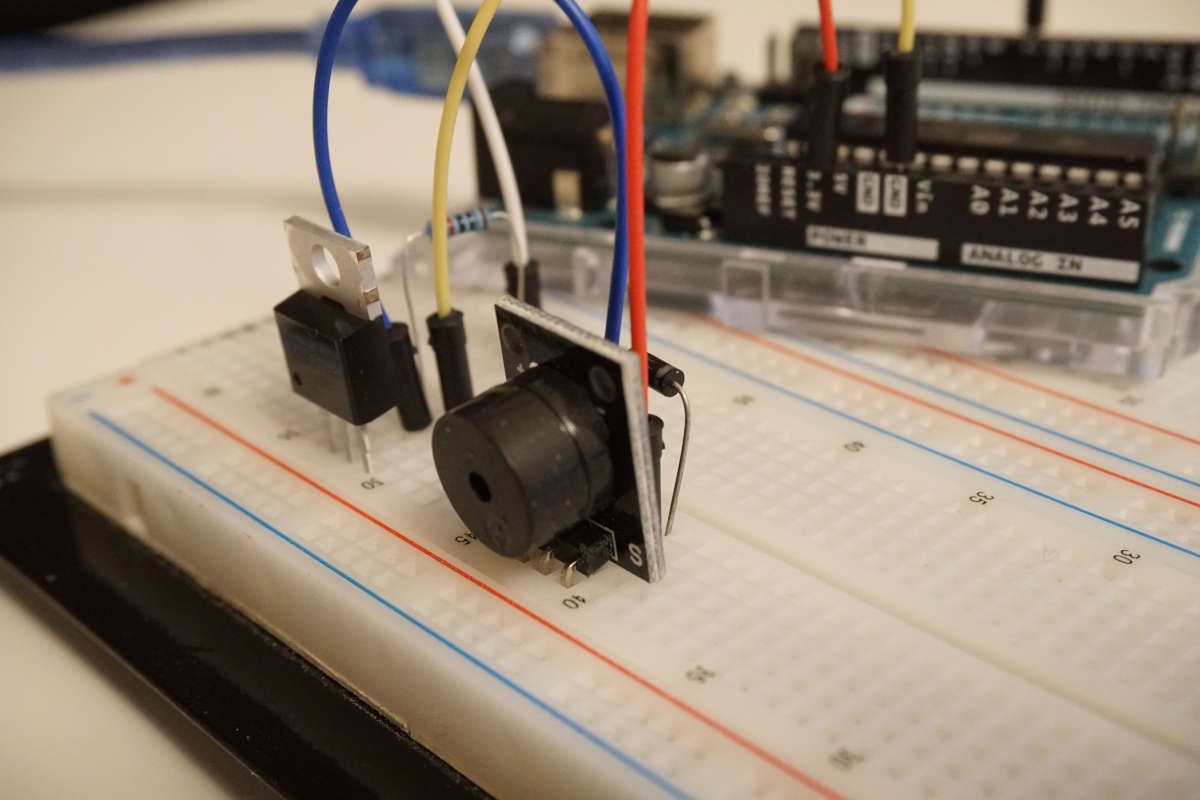
Table of Contents
Overview of Different Types of Buzzers
There are different types of buzzer that can be differentiated by two key factors:
- Does the buzzer has a build-in oscillator (active or passive buzzer)?
- How is the tone generated (piezo or magnetic buzzer)
With these independent factors, there are in total four different combinations of buzzers that are shown in the following picture.
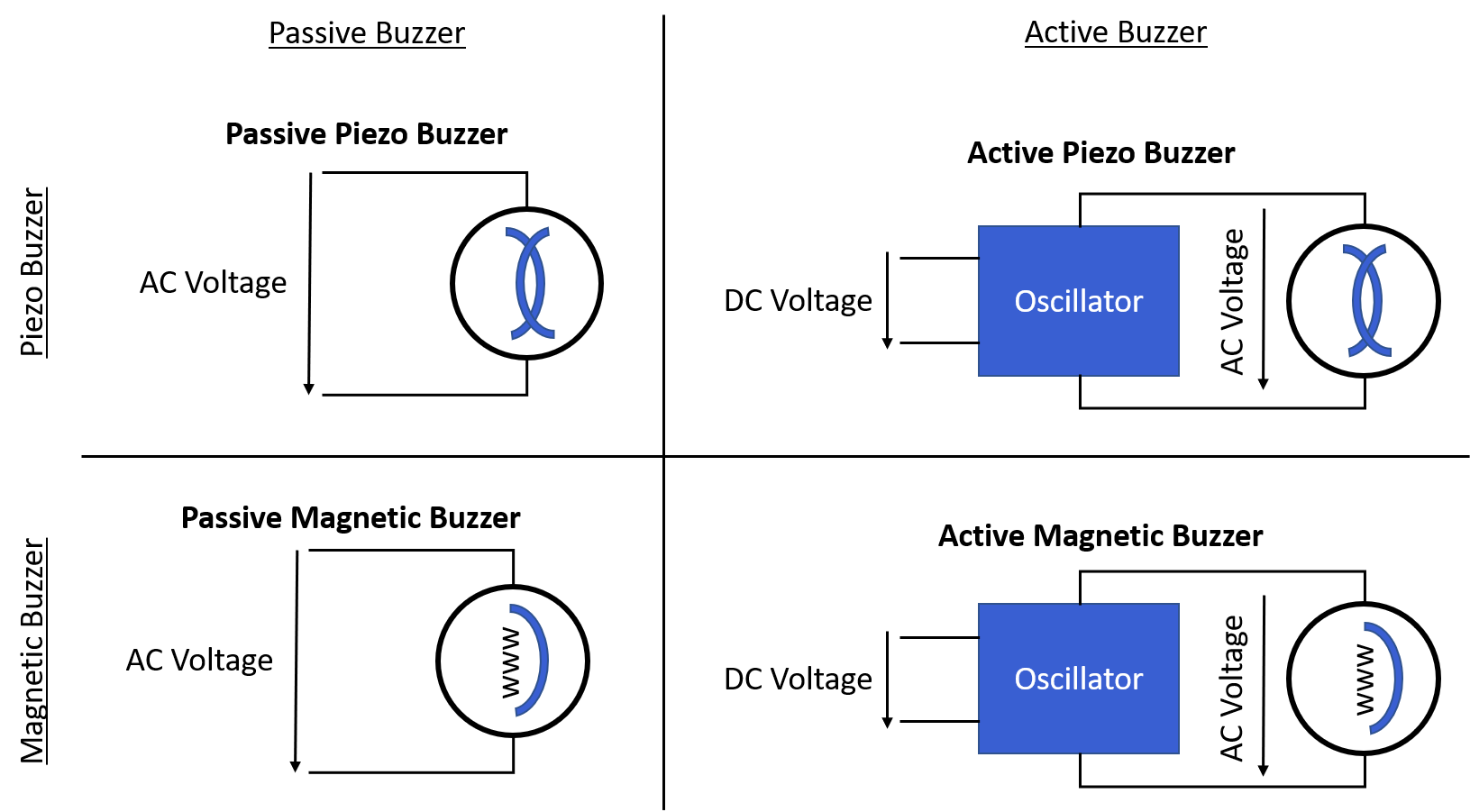
- Passive Piezo Buzzer: The tone is generated by a piezo buzzer and there is no internal oscillator
- Active Piezo Buzzer: The tone is also generated by a piezoelectric diaphragm and the buzzer has a build-in oscillator.
- Passive Magnetic Buzzer: There is no internal oscillator and the tone is generated by a magnetic buzzer.
- Active Magnetic Buzzer: The internal oscillator provides the AC signal for the magnetic buzzer.
In the following sections we dive deeper into the different types of buzzers.
Difference Between Passive and Active Buzzer
The main difference between an active buzzer and a passive buzzer is, that the active buzzer has a build-in oscillator where the passive buzzer has no internal oscillator. All other differences are deducted from this main difference and summarized in the following table.
| Passive Buzzer | Active Buzzer | |
|---|---|---|
| Oscillator | No internal oscillator | Build-in oscillator |
| Voltage Supply | AC voltage | DC voltage or square wave signals |
| Lead length | Same length of leads | Positive connection has longer lead |
| Relative Price | Cheap | Expensive |
| Identification | Without sicker on top | With white sicker on top |
There is a very hand trick to differentiate between an active and passive buzzer, when you can not identify the buzzer with the sticker on top: Connect the buzzer properly to a battery. If the buzzer generates a sound, it is an active buzzer. If there is no sound, the buzzer is a passive buzzer.
Schematic and Functionality of Passive Buzzer
To create a tone, the buzzer needs a oscillating AC signal that has to be provided by the microcontroller for the passive buzzer, because there is no internal oscillator. The passive buzzer is like an speaker where the changing input signal produces the sound. If you connect a DC power source to a passive buzzer, you will hear no sound. Only if you connect the power source you will hear a tone.

Because you have full control over the AC voltage signal, you can control the pitch and create different tones which we see in the passive buzzer sound example.
How can an AC signal with Arduino, ESP8266 or ESP32 microcontroller? We use the Arduino tone function that generates a square wave of the specified frequency (and 50% duty cycle) on a digital I/O pin.
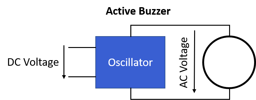
Schematic and Functionality of Active Buzzer
The active buzzer generates a tone using an internal oscillator, that creates an alternating voltage signal for the buzzer based on the external DC voltage. Because the oscillator can not be changed, the active buzzer can only play a single tone with a predefined frequency of 2300 Hz +- 300 Hz when a constant DC voltage is provided.
When you connect the active buzzer with an Arduino, ESP8266 or ESP32 microcontroller you have to make sure that the positive line is connected to the longer leg of the active buzzer.
Instead of a constant DC signal, you can also create some variety of tones by applying an oscillating signal to the active buzzer. Compared to the passive buzzer, the tones that can be created is very limited and not quite as clean.
The main advantage of the active buzzer is that no processing power, hardware timers, or additional code is needed to produce a sound and therefore mostly used in security, air conditioning, refrigerator, printer, automotive electronics electronic products.
Difference Between Piezo and Magnetic Buzzer
Buzzers can also be categorized by the functionality that generates the tone. The two most used types for microcontroller are the piezo buzzer and the magnetic buzzer. The following table shows the main differences between a piezo and a magnetc buzzer.
| Piezo Buzzer | Magnetic Buzzer | |
|---|---|---|
| Operation Voltage | 12V...220V | 1.5V...12V |
| Current Consumption | < 20mA | > 20mA |
| Relative Maximum Sound Pressure Level (SPL) | 85...120 db | 70...95dB |
| Resonant Frequency | 2...6 kHz | 1...3 kHz |
In the following two sections we take a closer look at the construction and the functionality of the piezo and the magnetc buzzer.
Construction and Functionality of Piezo Buzzer
Piezo buzzers are designed to be used for larger voltages, normally between 12V and 220V with a current consumption of under 20mA. Because of the higher voltages, the piezo buzzer has typically a greater maximum sound pressure level (SPL) between 85db and 120db than magnetic buzzers.
A piezo element responds to voltage at any frequency, but much more strongly at its mechanical resonant frequency between 2 kHz and 6 kHz.
The following picture shows the construction of a piezo buzzer.
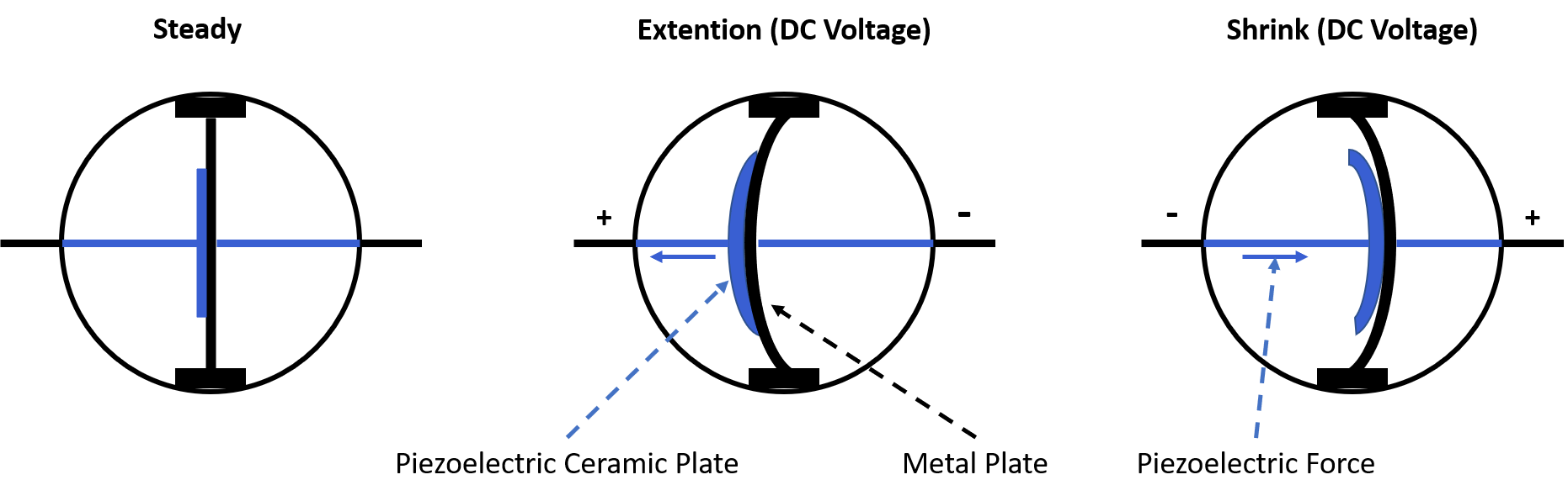
The sound source of the piezo buzzer is the piezoelectric diaphragm that consists of two key components that:
- A piezoelectric ceramic plate that is connected to the DC power source.
- A metal plate that is connected to the piezoelectric ceramic plate with adhesives and also to the enclosure of the piezo buzzer.
When there is no DC voltage supplied to the piezo buzzer, the buzzer does not make any sound and the piezoelectric ceramic plate as well as the metal plate are in their neutral position.
Applying DC voltage to the buzzer, the piezoelectric ceramic plate reacts to the voltage with a piezoelectric force in radial direction that causes mechanical distortion to the piezoelectric diaphragm. Depending on the polarity of the DC voltage, the piezoelectric ceramic plate bends (extends or shrinks), because the metal plate, that is connected to the ceramic plate, is connected to the enclosure.
Therefore, when an AC voltage is applied to the piezo buzzer, the bending is repeated, producing sound waves in the air.
Construction and Functionality of Magnetic Buzzer
Compared to the piezo buzzer, the magnetic buzzer operates at lower voltages between 1.5V and 12V but needs higher current of greater 20mA.
Also the magnetic buzzer responds much more strongly at its mechanical resonant frequency between 1 kHz and 3 kHz. The Maximum Sound Pressure Level (SPL) is between 70db…95db and therefore lower compared to the piezo buzzer.
The following picture shows the construction of a magnetic buzzer.
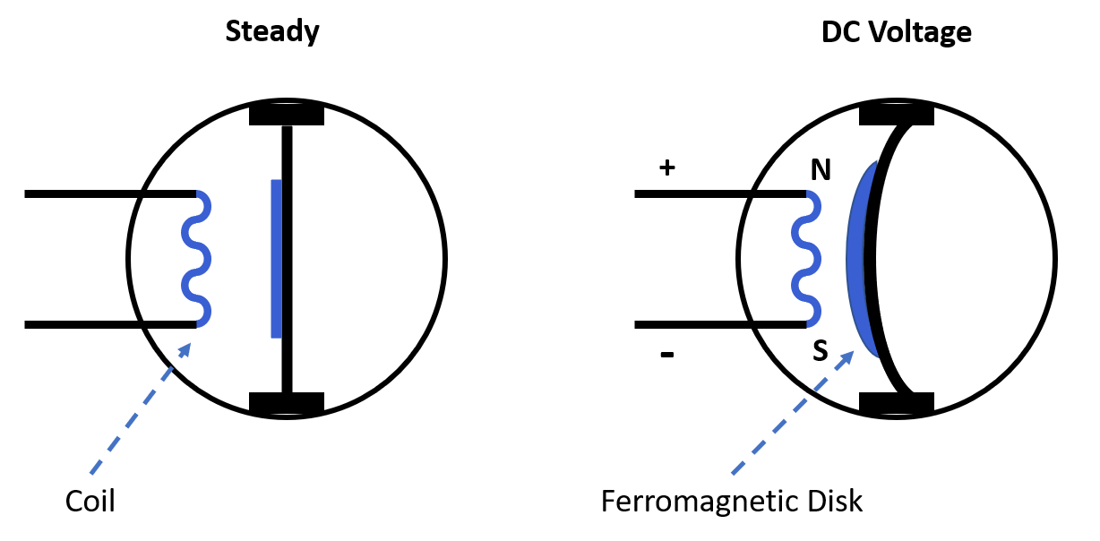
The two key components of a magnetic buzzer are a coil of wire and a ferromagnetic disk. The coil of wire is connected to the power supply of the magnetic buzzer. If a current drives through the coil, an magnetic field is produced.
The flexible ferromagnetic disk is connected to the enclosure of the buzzer and attracted to to coil when a magnetic field is present. If an AC voltage is applied, the ferromagnetic disk moves back and forth and creates a tone in similar manner to how a tone is created by a speaker.
The magnetic field, that is the source of the tone is created by the current that is determined by the applied voltage and the impedance of the coil. Therefore the magnetic buzzer is a current driven device.
The following table gives you an overview of all components and parts that I used for this tutorial. I get commissions for purchases made through links in this table.
| Component | Amazon Link | AliExpress Link |
|---|---|---|
| Arduino Nano | Amazon | AliExpress |
| Arduino Pro Mini | Amazon | AliExpress |
| Arduino Uno | Amazon | AliExpress |
| Arduino Mega | Amazon | AliExpress |
| ESP32 ESP-WROOM-32 | Amazon | AliExpress |
| ESP8266 NodeMCU | Amazon | AliExpress |
| ESP8266 WeMos D1 Mini | Amazon | AliExpress |
| Active and Passive Buzzer in Sensor Kit | Amazon | AliExpress |
Active and Passive Buzzer Microcontroller Circuit
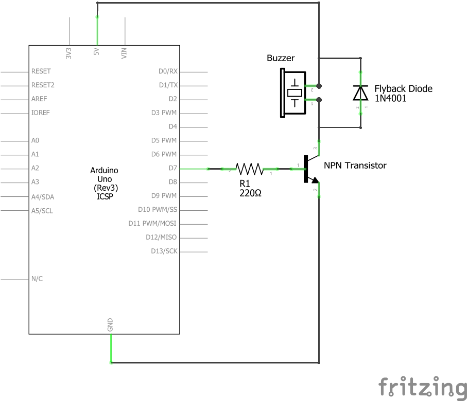
The following picture shows the circuit for active and passive buzzer. It is important to understand that the circuit is the same for the active and passive buzzer. The difference is only the control of the buzzer via the program code that we see in the programming part of this tutorial where we create a sound with an active buzzer and a melody with a passive buzzer.
In the following sections we describe the circuit and the electronic components in detail to understand the functionality of the circuit.
Why do we use a Transistor to control the buzzer?
When we create the circuit to control an active or passive buzzer with an Arduino, ESP8266 or ESP32 microcontroller, we have to keep in mind that the maximum current of the digital I/O pins of the microcontroller is limited. If the buzzer consumes more current than the maximum current of the digital pin is able to provide we need another solution.
The following table shows the maximum current of the digital input/output pins of the most used microcontroller boards. This information is also included in my Microcontroller Datasheet eBook.
| Microcontroller | Boards | Max Current Digital I/O Pin |
|---|---|---|
| ATmega328P | Arduino Nano, Arduino Uno, Arduino Pro Mini | 40 mA |
| ATmega2560 | Arduino Mega | 20 mA |
| ESP8266 | ESP-01, NodeMCU, WeMos D1 Mini | 12 mA |
| ESP32 | DevKitC, Adafruit HUZZAH32, Sparkfun ESP32 Thing Plus, FireBeetle ESP32 | 20 mA |
Piezo buzzer have a current consumption lower than 20mA and could therefore be powered by Arduino microcontroller as well as the ESP32. But if we want to use magnetic buzzers with a current consumption higher than 20mA we have to find a different power supply than the digital I/O pin of the microcontroller.
The solution is to use a transistor and divide between the control signal and the power consumption. In my case I use the IRLZ44 NPN MOSFET as low-side transistor to control the buzzer.
- NPN transistor: Because we want to turn the active or passive buzzer on by setting the digital pin of the microcontroller HIGH.
- Low-side switch: The transistor is on the low (ground) side of the circuit and the buzzer is connected on the high (5V or 3.3V) side. Otherwise we were not able to switch off a load that has a higher voltage than the control voltage.
The digital I/O pin of the Arduino, EPS8266 or ESP32 microcontroller is therefore connected to the gate of the MOSFET with a resistor of 220Ω in series, because the Arduino operation voltage of 5V or even the 3.3V operation voltage of the ESP8266 or ESP32 would damage the transistor.
For the wiring, make sure to know the positions of the gate, source and drain of your MOSFET that you are using. For example: In the fritzing sketch of the wiring, the gate is in the middle but for the IRLZ44, the gate is the left pin.
Why do we need a diode in parallel to the Buzzer?
If the buzzer is switched off, the vibration of the piezo and magnetic buzzer can lead to voltage spikes because:
- for the piezo buzzer, the piezo effect works both ways and the mechanical stress can create a voltage
- for the magnetic buzzer, the self-induction in the coil can create a voltage
The diode, also called flyback diode, that we set in parallel to the active or passive buzzer provides a safe path for the inductive current so that the voltage does not rise and damages the circuit.
Difference between a Buzzer and a Buzzer Module
If you want to build your own current, you have to know if you have a standard buzzer in front of you or a buzzer module. The difference between a buzzer and a buzzer module is quite simple. A buzzer is only the buzzer itself and the buzzer module contains also the transistor, the resistor and dependent on the module also a power LED. The following two pictures show clearly the difference.
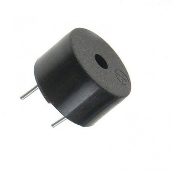
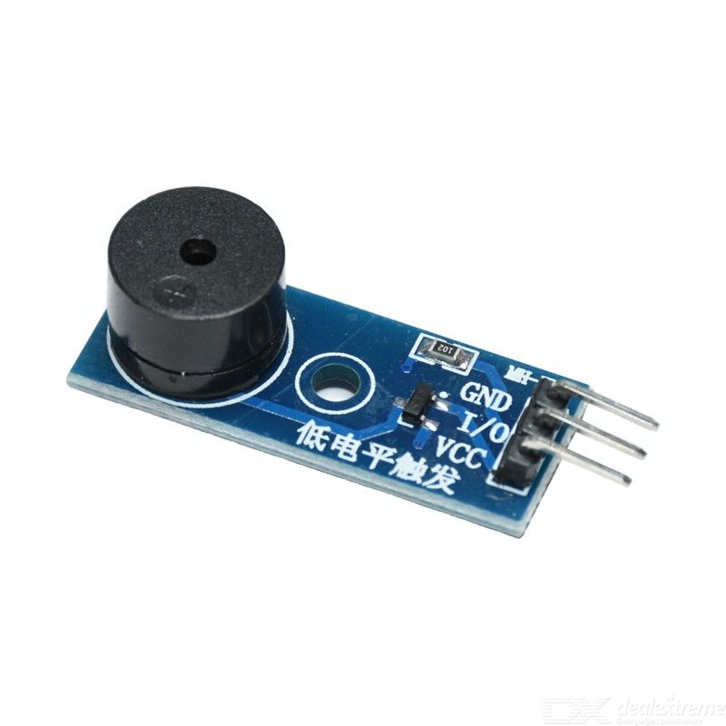
If you have a buzzer module, the wiring between the module and the Arduino, EPS8266 or ESP32 microcontroller board is very easy. You only have to connect the power supply, ground and the digital I/O pin to the module and you are ready to go.
Wiring between Buzzer and Arduino Boards
The wiring between the active or passive buzzer and different Arduino microcontroller is shown in the following pictures. If your favorite Arduino microcontroller boards is missing and you need the wiring for this board, use the comment section below and I will add this board to the tutorial.
- The 5V output of the Arduino microcontroller is connected to the positive pole of the buzzer and also connected to the cathode of the diode.
- The negative pole of the buzzer is connected to the anode side of the diode and also to the drain connection of the NPN MOSFET.
- The digital pin of the Arduino is connected via a 220Ω resistor to the gate of the MOSFET and the circuit is closed with the connection of the source pin of the MOSFET to the ground of the Arduino board.
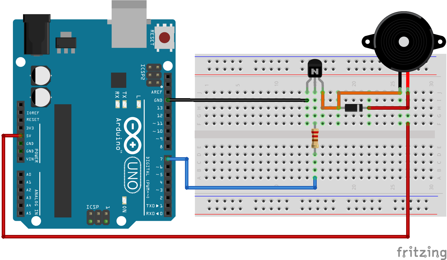
For more information about the Arduino Uno, visit the Arduino Uno Tutorial.
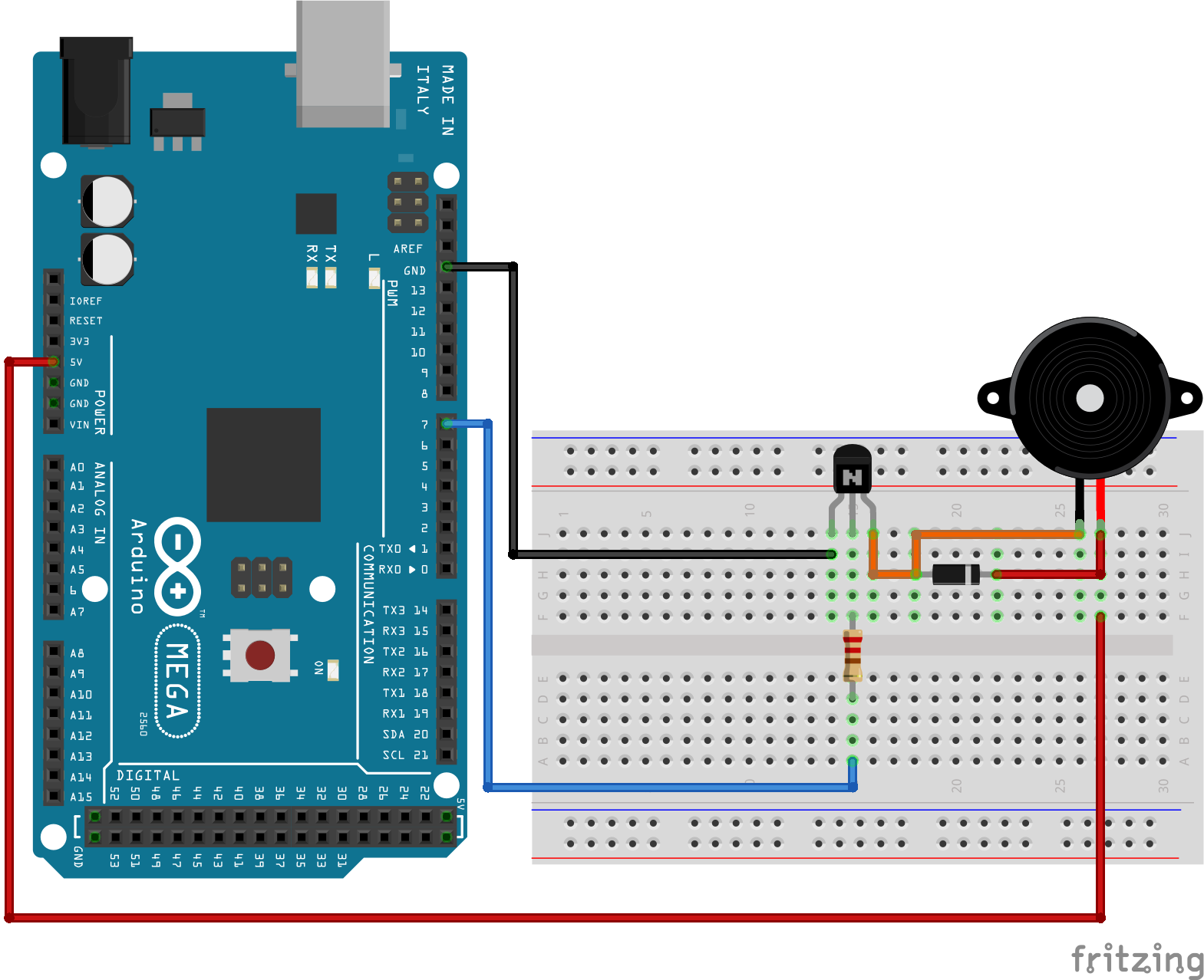
For more information about the Arduino Mega, visit the Arduino Mega Tutorial.
Wiring between Buzzer and ESP8266 Boards
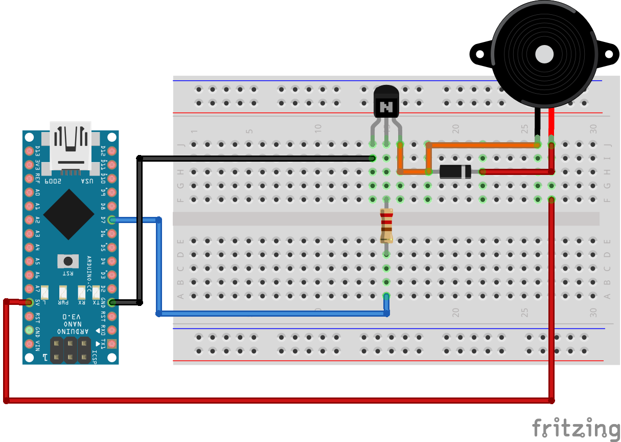
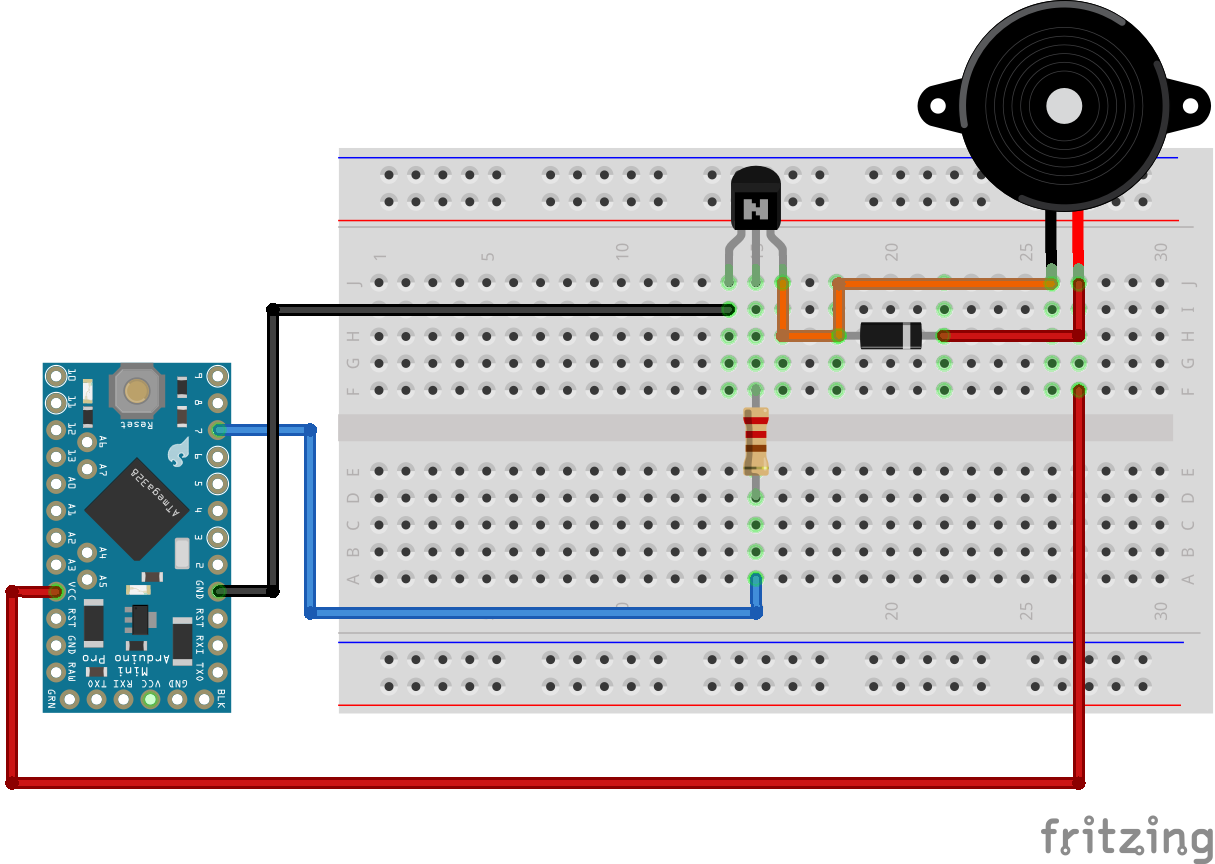
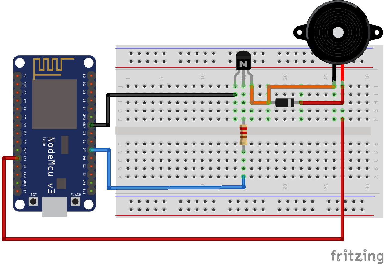
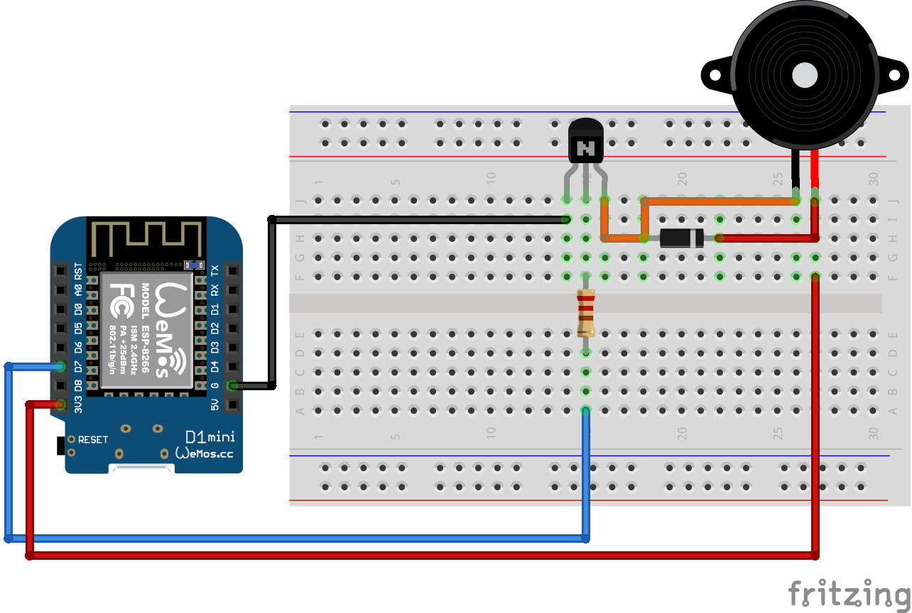
The wiring between the active or passive buzzer and the ESP8266 NodeMCU or ESP8266 WeMos D1 Mini is shown in the following pictures. If your favorite ESP8266 microcontroller boards is missing and you need the wiring for this board, use the comment section below and I will add this board to the tutorial.
- Start the wiring for the ESP8266 NodeMCU or WeMos D1 Mini by connecting the positive pole of the active or passive buzzer with the 3.3V pin of the ESP8266 microcontroller.
- Then connect the negative pole of the buzzer with the drain of the IRLZ44 NPN MOSFET.
- Now you can connect the flyback diode in parallel but make sure that the diode is connected with the right polarity.
- The next step is to connect the source of the MOSFET to ground of the ESP8266 and for the last step in the wiring you connect your preferred digital I/O pin (in my case D7) with a 220Ω resistor in series to the gate of the NPN MOSFET.
Wiring between Buzzer and ESP32 Boards
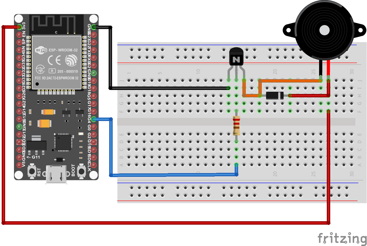
The following picture shows the wiring between the active or passive buzzer and the ESP32 ESP-WROOM-32. If your favorite ESP32 microcontroller boards is missing and you need the wiring for this board, use the comment section below and I will add this board to the tutorial.
- Start the wiring by connecting the 3V3 pin of the ESP32 microcontroller to the positive pole of the buzzer.
- The negative pole of the active or passive buzzer is connected to the drain of the NPN MOSFET.
- Now you can place the flyback diode in parallel to the buzzer but watch out for the polarity of the diode.
- The digital I/O pin of the ESP32, in my case pin 4 is connected to the gate of the IRLZ44 NPN MOSFET with a resistor of 220Ω in series to limit the voltage drop over the MOSFET.
- Finish the wiring by connecting the source of the MOSFET with the ground pin of the ESP32.
Microcontroller Datasheet eBook
The 35 pages Microcontroller Datasheet Playbook contains the most useful information of 14 Arduino, ESP8266 and ESP32 microcontroller boards.
Creating a Sound with an Active Buzzer
For the active buzzer we create a very simple sound example. We turn the active buzzer on and off for one second in a loop.
The following section shows the Arduino program code for Arduino, ESP8266 and ESP32 microcontroller. Depending on the commented first three lines, the script can be used for all of these microcontrollers.
int Buzzer = 7; //for Arduino Microcontroller
//int Buzzer = D7; //for ESP8266 Microcontroller
//int Buzzer = 4; //for ESP32 Microcontroller

void setup(){
  pinMode (Buzzer, OUTPUT);
}

void loop(){
  digitalWrite (Buzzer, HIGH); //turn buzzer on
  delay(1000);
  digitalWrite (Buzzer, LOW);  //turn buzzer off
  delay(1000);
}
The first three lines define the digital I/O pin that is connected to the gate of the MOSFET with a resistor in series. Uncomment the line of code for your microcontroller and comment or delete the other two lines.
In the setup function we define that the digital pin that we defined is an output because we want to control the buzzer and do not read any digital signal.
The loop function starts by setting the digital pin HIGH to turn on the active buzzer by activating the switch function of the MOSFET. After a delay of 1 second, we turn of the voltage on the gate by setting the digital pin LOW. Therefore the MOSFET blocks the current for the buzzer and the buzzer turns off. We wait for one second and the loop function starts again.
The following video shows the program code for the active buzzer in action. Note that I use a buzzer module and therefore no other electronic parts like the MOSFET or diode is needed.

Creating a Melody with a Passive Buzzer
The passive buzzer has the advantage that we can not only create a tone, but also a melody with different frequencies. Let me know in the comment section if you know the melody that we create in this example.
To create a melody the passive buzzer needs an AC signal where we can define the frequency. Therefore we can not use the analog write function, because this function has a fixed frequency of 500Hz.
Instead we use the Arduino tone function to generate a square wave of the specified frequency (and 50% duty cycle). You could now use the tone function and define the connected output pin, the frequency and the duration of the output generation, but if you do not know the frequency of different notes, we can also use the pitches library from Mike Putnam.
If you take a look into the source code of the library you see that the library is nothing else than a lookup table for different notes to their frequency. The pitches library is not found in the Arduino IDE but you can download the ZIP file from Github and include the library in the Arduino IDE by clicking in the menu line: Sketch -> Include Library -> Add .ZIP Library.
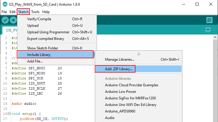
Now select the downloaded ZIP file from Github with the pitches library inside and you are ready to go.
The following section shows the program code that I created for the passive buzzer.
#include "pitches.h"

const int buzzerPin = 7; //for Arduino Microcontroller
//const int buzzerPin = D7; //for ESP8266 Microcontroller
//const int buzzerPin = 4; //for ESP32 Microcontroller

void beep(int note, int duration){
  tone(buzzerPin, note, duration);
  delay(duration);
}

void setup(){
  pinMode(buzzerPin, OUTPUT);
}

void loop() {
  beep(NOTE_A4, 500);
  beep(NOTE_A4, 500);
  beep(NOTE_A4, 500);
  beep(NOTE_F4, 350);
  beep(NOTE_C5, 150);
  beep(NOTE_A4, 500);
  beep(NOTE_F4, 350);
  beep(NOTE_C5, 150);
  beep(NOTE_A4, 650);

  delay(500);

  beep(NOTE_E5, 500);
  beep(NOTE_E5, 500);
  beep(NOTE_E5, 500);
  beep(NOTE_F5, 350);
  beep(NOTE_C5, 150);
  beep(NOTE_GS4, 500);
  beep(NOTE_F4, 350);
  beep(NOTE_C5, 150);
  beep(NOTE_A4, 650);

  delay(500);

  beep(NOTE_A5, 500);
  beep(NOTE_A4, 300);
  beep(NOTE_A4, 150);
  beep(NOTE_A5, 500);
  beep(NOTE_GS5, 325);
  beep(NOTE_G5, 175);
  beep(NOTE_FS5, 125);
  beep(NOTE_F5, 125);
  beep(NOTE_FS5, 250);

  delay(325);

  beep(NOTE_AS4, 250);
  beep(NOTE_DS5, 500);
  beep(NOTE_D5, 325);
  beep(NOTE_CS5, 175);
  beep(NOTE_C5, 125);
  beep(NOTE_AS4, 125);
  beep(NOTE_C5, 250);

  delay(350);
}
At the beginning of the Arduino script we include the pitches library and define the digital I/O pin that is connected to the gate of the MOSFET. Because the code can be used for Arduino, ESP8266 and ESP32 microcontroller boards, you have to uncomment the line of code for your microcontroller and delete or comment the other two lines.
To create the sounds via the tone function we create a helper function called beep that has the note and the duration for the tone as arguments. We use the tone function on the digital pin with the note of the pitches library and play the tone for the defined duration. After we the sound, we wait for the same time without any tone.
In the setup function we define that the digital pin that we defined is an output because we want to control the buzzer and do not read any digital signal.
In the loop function, we create the melody by using the beep function with the note we want to play and the duration of the sound. Using multiple sound and delays create a melody that you know.
The following video shows the melody example with a passive buzzer in action. Note that I use a buzzer module and therefore no other electronic parts like the MOSFET or diode is needed.
You can also try to use the same wiring and program code for the active buzzer. It will work but you will notice that the melody is not as clean compared to the passive buzzer.
If you have any questions, regarding the active or passive buzzer, use the comment section below to ask you questions and I will answer then as soon as possible.

Does a magnetic active buzzer (indicator), which has a build in circuitry, really need an flyback diode?
I mean this diode should already be built in, or not?!
See: https://media.digikey.com/pdf/Application%20Notes/CUI%20Application%20Notes/Buzzer_Basics.pdf