Arduino Uno Tutorial [Pinout]
In this tutorial you learn everything you have to know about the Arduino Uno:
- Technical datasheet
- What is the pinout of the Uno?
- What is the best power supply for this microcontroller?
- Advantages and Disadvantages of the Arduino Uno.
- Compare the Uno to other Arduino and ESP8266 based microcontroller.
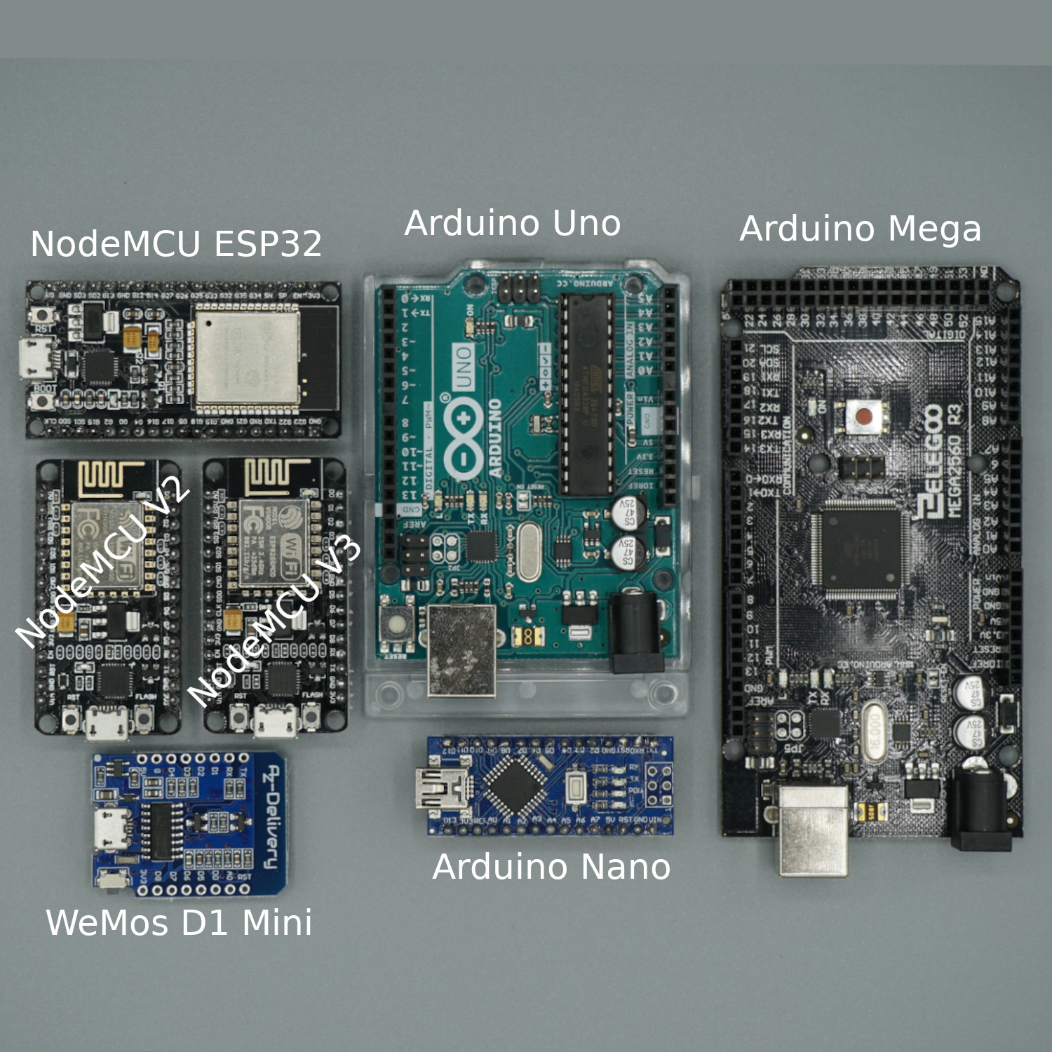
Table of Contents
The Arduino Uno is a microcontroller board, based on the ATmega328P (for Arduino UNO R3) or ATmega4809 (for Arduino UNO WIFI R2) microcontroller by Atmel and was the first USB powered board of Arduino. The Atmega328 and ATmega4809 comes with built-in bootloader, which makes it very easy to flash the board with your code. Like all Arduino boards, you can program the software running on the board using a language derived from C and C++. The easiest development environment is the Arduino IDE.
The following table contains the datasheet of the microcontroller board:
| Arduino UNO R3 | Arduino UNO WIFI R2 | |
| Microcontroller | ATmega328p | ATmega4809 |
| Operating Voltage | 5 V | 5 V |
| Power supply | 7 V – 12 V | 7 V – 12 V |
| Current consumption | 45 mA – 80 mA | 50 mA – 150 mA |
| Current consumption Deep Sleep | 35 mA | 35 mA |
| Digital I/O Pins | 14 | 14 |
| Digital I/O Pins with PWM | 6 | 5 |
| Analog Input Pins | 6 | 6 |
| SPI/I2C/I2S/UART | 1/1/1/1 | 1/1/1/1 |
| DC Current per I/O Pin | 20 mA | 20 mA |
| DC Current for 3.3V Pin | 50 mA | 50 mA |
| Flash Memory | 32 KB | 48 KB |
| SRAM | 2 KB | 6 KB |
| EEPROM | 1024 bytes | 256 bytes |
| Clock Speed | 16 MHz | 16 MHz |
| Length | 69 mm | 69 mm |
| Width | 53 mm | 53 mm |
| WIFI | no | yes |
| Bluetooth | no | no |
| Touch sensor | no | no |
| CAN | no | no |
| Ethernet MAC Interface | no | no |
| Temperature Sensor | no | no |
| Hall effect sensor | no | no |
| Power jack | yes | yes |
| USB connection | yes | yes |
| Price | $22 | $44.90 |
Do you want to compare the datasheet of different microcontroller boards like Arduino Mega, Arduino Nano, ESP8266 Node MCU and WeMos D1 Mini? Follow this Link for the comparison.
If you do not already have an Arduino Uno, you can buy one from the following links. I get commissions for purchases made through links in this table.
| Arduino Uno | Amazon | Banggood | AliExpress |
Arduino Uno Pinout
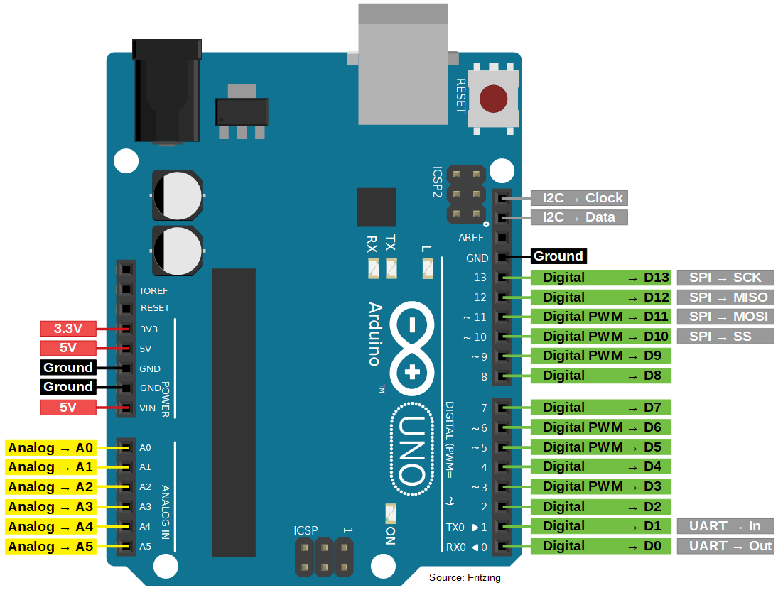
The Arduino Uno has a lot of different pins and therefore we want to go over the different kinds of pins.
The Uno has in total three power pins of which one has a supply voltage of 3.3V and two pins provide 5V. All power pins have a maximum current of 50 mA. You can use the VIN pin to power the whole microcontroller with a voltage between 7V-12V, also perfect for a battery. Of cause if you have power pins you also need some ground pins to close the electric circuit. The Arduino Uno has in total three ground pins which are all connected internally.
To connect analog sensors like a temperature sensor, the Arduino has six analog pins. Internally the analog signal is converted into an digital signal with a 10-bit analog-to-digital converter (ADC). Therefore analog voltages are represented by 1024 digital levels (0-1023). You can also use an analog pin to write analog signals with the function digitalWrite(Ax) where Ax is the analog pin, for example A3.
The Arduino Uno has in total 14 digital pins which provide a maximum current of 20 mA. Six of the 14 digital I/O pins are able to produce a PWM signal.
If you want to communicate between multiple devices you need communication pins which are also provided by the Arduino. The microcontroller has for each communication protocol (I2C, SPI, UART) one group of pins.
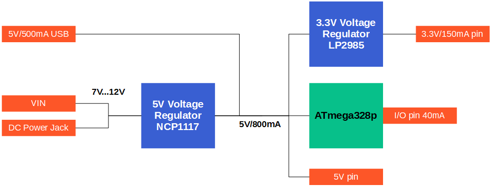
Arduino Uno Power Supply
The Arduino Uno Power Supply depends on the electrical components that are on the PCB. The following picture gives an overview about all relevant components to get an overview of the different voltage levels on the Arduino and also the maximum currents.
The main component of the Arduino Uno is the microprocessor ATmega328p. The following table shows the minimum, operation and maximum voltage.
Microcontroller | Minimum Voltage | Typical Voltage | Maximum Voltage |
ATmega328p | 2.7V | 5V | 6V |
Because the operation voltages is 5V, there are two build in voltage regulators that provide a stable 5V and 3.3V output voltage.
Arduino Uno Voltage Regulators
The following table shows the important technical details of the voltage regulators regarding the power supply.
Voltage Regulator | Output Voltage | Maximum Input Voltage | Maximum Output Current |
NCP1117ST50T3G | 5V | 20V | 800mA |
LP2985-33DBVR | 3.3V | 16V | 150mA |
The NCP1117ST50T3G is connected to the VIN pin and the DC power jack. Technically the maximum input voltage is 20V but because at 20V the voltage regulator is producing a lot of heat and would break after a short time period, it is recommended to supply an input voltage between 7V and 12V. The NCP1117 provides a stable output voltage of 5V and a maximum current of 800mA for the ATmega328p.
The ATmega328p can also be powered via the USB connection, that I use a lot in my projects. There is no need for a voltage regulator because the USB connection is already regulated by the USB output from your PC or laptop. The maximum current draw from the USB connection is 500mA.
The second voltage regulator, 3.3V LP2985, has an input voltage of 5V and reduces the voltage to 3.3V for the 3.3V pin of the Uno. Regarding the data sheet of the LP2985, the maximum current is 150mA but on the official Arduino website, the maximum current should be 50mA. I never needed more than 50mA on the 3.3V pin, but in my opinion, a current draw of around 100mA should be possible.
The 5V pin of the Arduino Uno is directly connected to the 5V voltage regulator and supports a maximum current that is defined by the difference of the current provided by the voltage regulator and the current from the ATmega328p.
Maximum Current for I/O Pins
Each I/O pin supports a maximum current of 40mA but it is not possible to draw 40mA current over each pin because the maximum allowed current load of the port registers must be considered.
The digital and analog pins of the ATmega328p are connected to different port registers and each port register supports a maximum allowed current that depends on if the register is used as source or as sink. The following table shows which pin is assigned to which port register and also the maximum current.
Pins | D0…D4 | D5…D7 | D8…D13 | A |
Port Register | D0…D4 | D5…D7 | B0…B5 | C0…C5 |
Max Current Source 150mA | ||||
Max Current Sink 100mA |
There are in total 3 port registers: D, B, C. All digital pins D0…D13 are assigned to register D and B. For the maximum current, port register D is separated. All analog pins belong to the port register C.
The maximum current, if the pins are a current source, is 150mA. The sum of all pins in the colored port register should not exceed 150mA:
- Current source of port register D0…D4 + C0…C5 < 150mA
- Current source of port register D5…D7 + B0…B5 < 150mA
If the I/O pin is a current sink, the maximum current is 100mA and divided into three groups:
- Current sink of port register D0…D4 < 100mA
- Current sink of port register D5…D7 + B0…B5 < 100mA
- Current sink of port register C0…C4 < 100mA
Three possibilities for the Power Supply
You can power your Arduino Uno in 3 save ways because a voltage regulator provides a regulated and stable voltage for the microprocessor:
- USB cable: The most popular and also the easiest way to power the microcontroller is via USB cable. The standard USB connection delivers 5V and allows you to draw 500mA in total.
- DC Power Jack: It is possible to use the DC power Jack as power supply. If you buy a DC power jack, make sure the power adapter of the plug supplies a voltage between 7V and 12V.
- VIN Pin: If you use an external power supply like a battery, you can use the VIN pin. The voltage has to be between 7V and 12V. Therefore you are able to power the Uno with an external 9 Volt battery.
You cannot power the board with the barrel jack and VIN GPIO at the same time, because there is a polarity protection diode, connecting between the positive of the barrel jack to the VIN pin, rated at 1A.
You can also power power the Arduino microcontroller from the 5V pin. This is not recommended because you bypass the NCP1117 voltage regulator and have to make sure that the voltage level is stable.
It is not possible to power the Arduino Uno via the 3.3V pin because the voltage regulator prevent a current flow in the opposite direction.
Arduino Uno Power Consumption
The ATmega328p microprocessor draws about 5.2mA depending on the clock frequency and the supply voltage. The following table shows the typical and maximum voltage for different clock frequencies and supply voltages.
Mode | Clock Frequency | Supply voltage | Typical current consumption | Maximum current consumption |
Active | 4MHz | 3V | 1.5 mA | 2.4 mA |
Active | 8MHz | 5V | 5.2 mA | 10 mA |
Active | 16MHz | 5V | 9.2 mA | 14 mA |
Idle | 4MHz | 3V | 0.25 mA | 0.6 mA |
Idle | 8MHz | 5V | 1 mA | 1.6 mA |
Idle | 16MHz | 5V | 1.9 mA | 2.8 mA |
The current consumption can be reduced, using the power-down mode. (WDT = Watchdog Timer)
Mode | WDT | Supply voltage | Maximum current consumption |
Power-down | enabled | 3V | 0.044 mA |
Power-down | enabled | 5V | 0.066 mA |
Power-down | disabled | 3V | 0.004 mA |
Power-down | disabled | 5V | 0.006 mA |
The activation of the power-down mode is easy if you use the Low-Power library from rocketscream. The following example scripts sets Arduino Mega in the deep-sleep mode for 8 seconds.
#include "LowPower.h"

void setup()
{
    // No setup is required for this library
}

void loop()
{
    // Enter power down state for 8 s with ADC and BOD module disabled
    LowPower.powerDown(SLEEP_8S, ADC_OFF, BOD_OFF);

    // Do something here
    // Example: Read sensor, data logging, data transmission.
}
If we want to know the power consumption of the Arduino Uno we have to add the current consumption of all electric parts on the PCB. Because the voltage regulators, LEDs and other parts needs also current for their functionality, the average current consumption of the Arduino Uno is around 45 mA.
Arduino Uno Advantages and Disadvantages
Advantages
- The ability to use a Power Jack as a power supply
- 6 analog input pins are for the most projects more than enough. The 1 analog input from the EPS8266 are for some projects too few.
Disadvantages
- For the Uno R3 there is no build in WiFi. Because most of my projects are related to the IoT sector I use WiFi in almost all my projects.
- The Uno does not have a deep sleep mode in comparison to the ESP8266.
Conclusion
The Arduino Uno is the standard Arduino board which is a good board for starters. The only real drawback is the missing WiFi. So make sure if your project already uses a WiFi connection or you would like to have this feature to upgrade your project in the future that you buy the Uno version with WiFi included. What are your thoughts on the Uno? Do you use this board and what were the reasons why you bought it? Use the comment section below for your answers.
Pin count is low to my opinion. If you want to add multiple (digital) sensors and a TFT and some other connections, it seems low given the amount of pins larger displays demand.
Hi Arjan,
of course the number of digital pins are limited. But also you can save some pins if you connect the TFT display via I2C (2 pins) and use a shift register to increase the number of digital inputs or outputs: https://diyi0t.com/shift-register-tutorial-for-arduino-and-esp8266/
am I wrong or I2C pins are swapped in your image ?
Hi,
yes you are right, my mistake. I updated the picture of the pinout so that the I2C pins are correct.