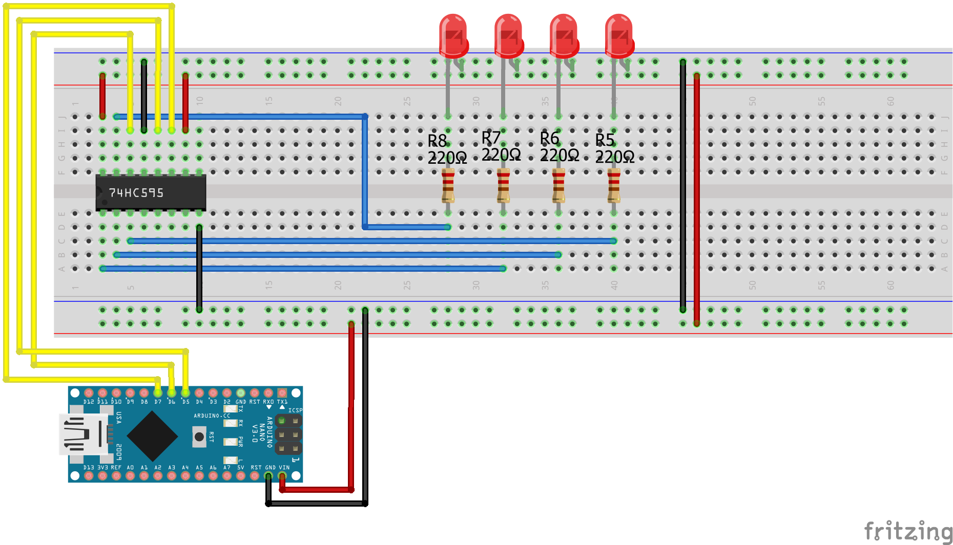
Shift Register SIPO Arduino Nano
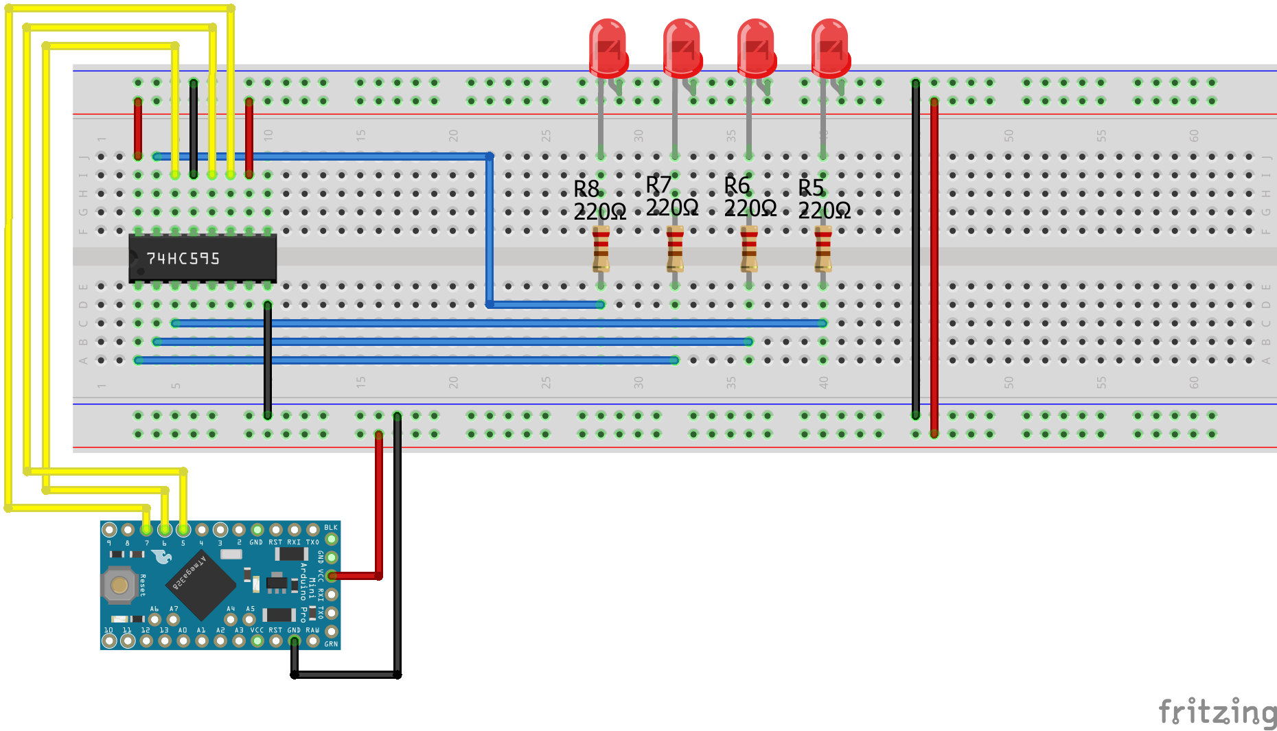
Shift Register SIPO Arduino Pro Mini
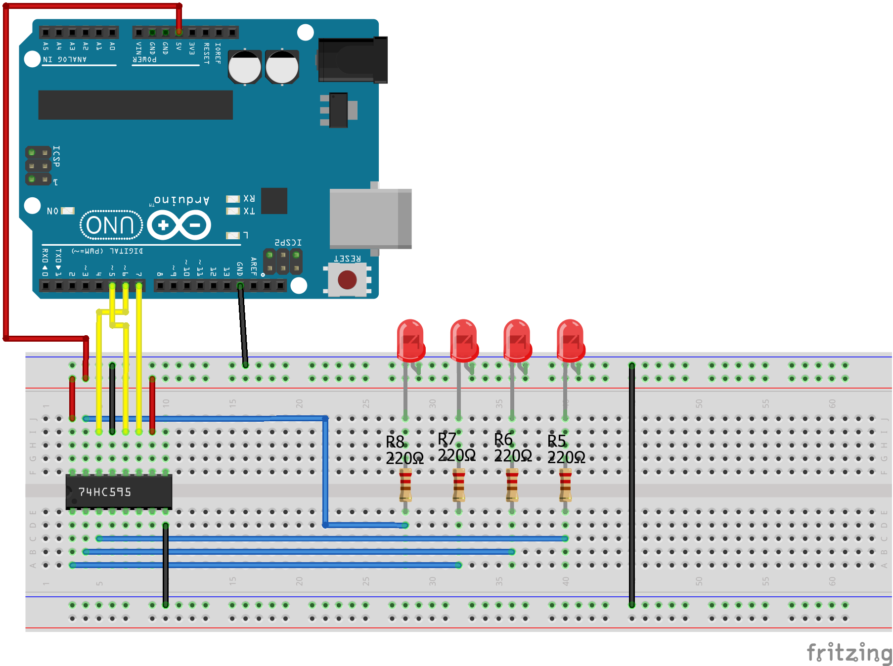
Shift Register SIPO Arduino Uno
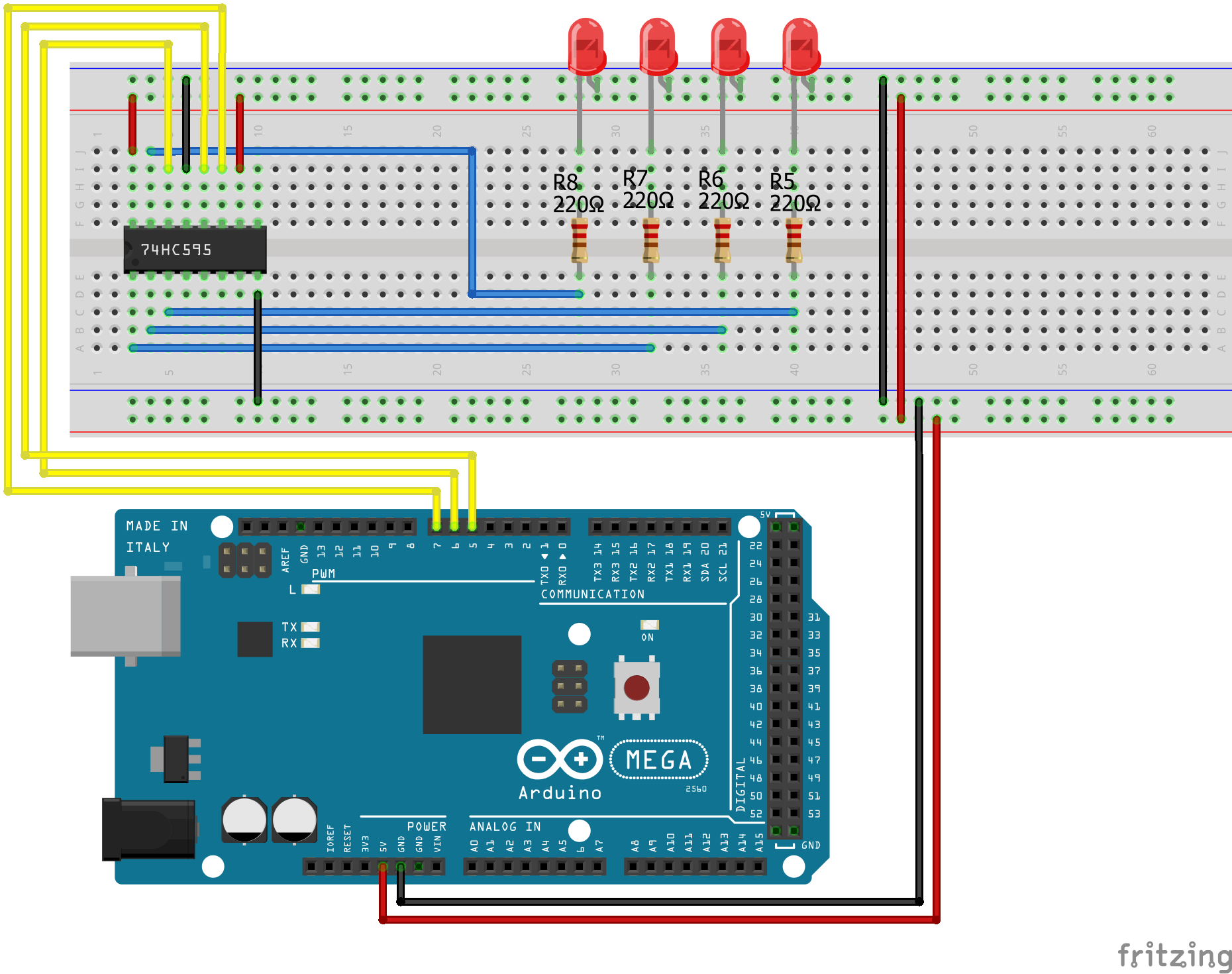
Shift Register SIPO Arduino Mega
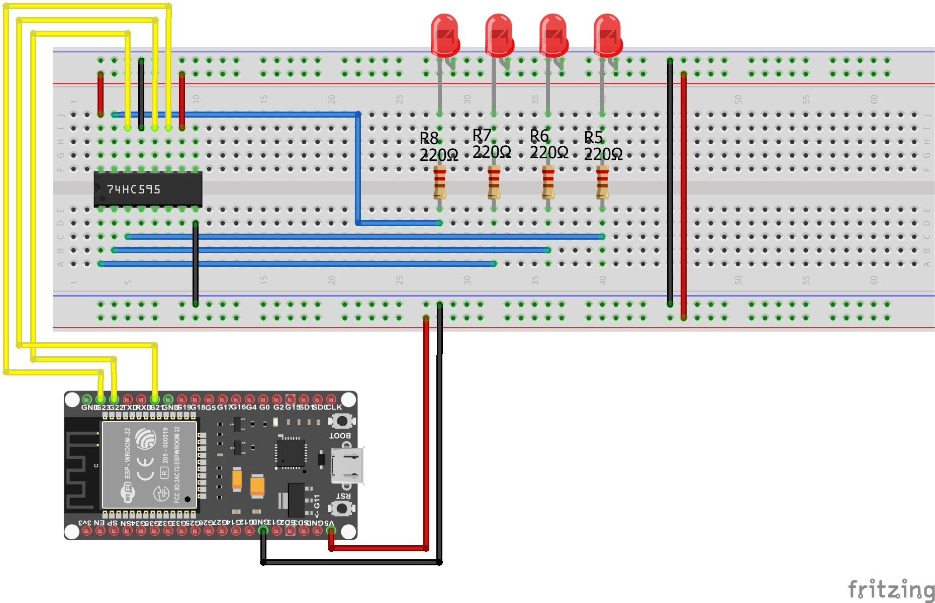
Shift Register SIPO EPS32 NodeMCU

Shift Register SIPO ESP8266 NodeMCU
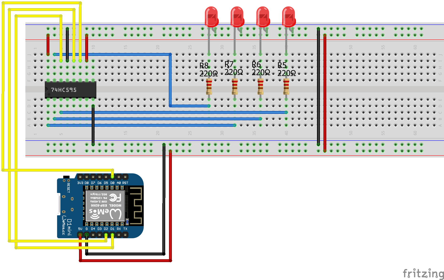
Shift Register SIPO ESP8266 WeMos D1 Mini
Shift Register PISO Pull Down Arduino Nano

Shift Register PISO Pull Down Arduino Pro Mini
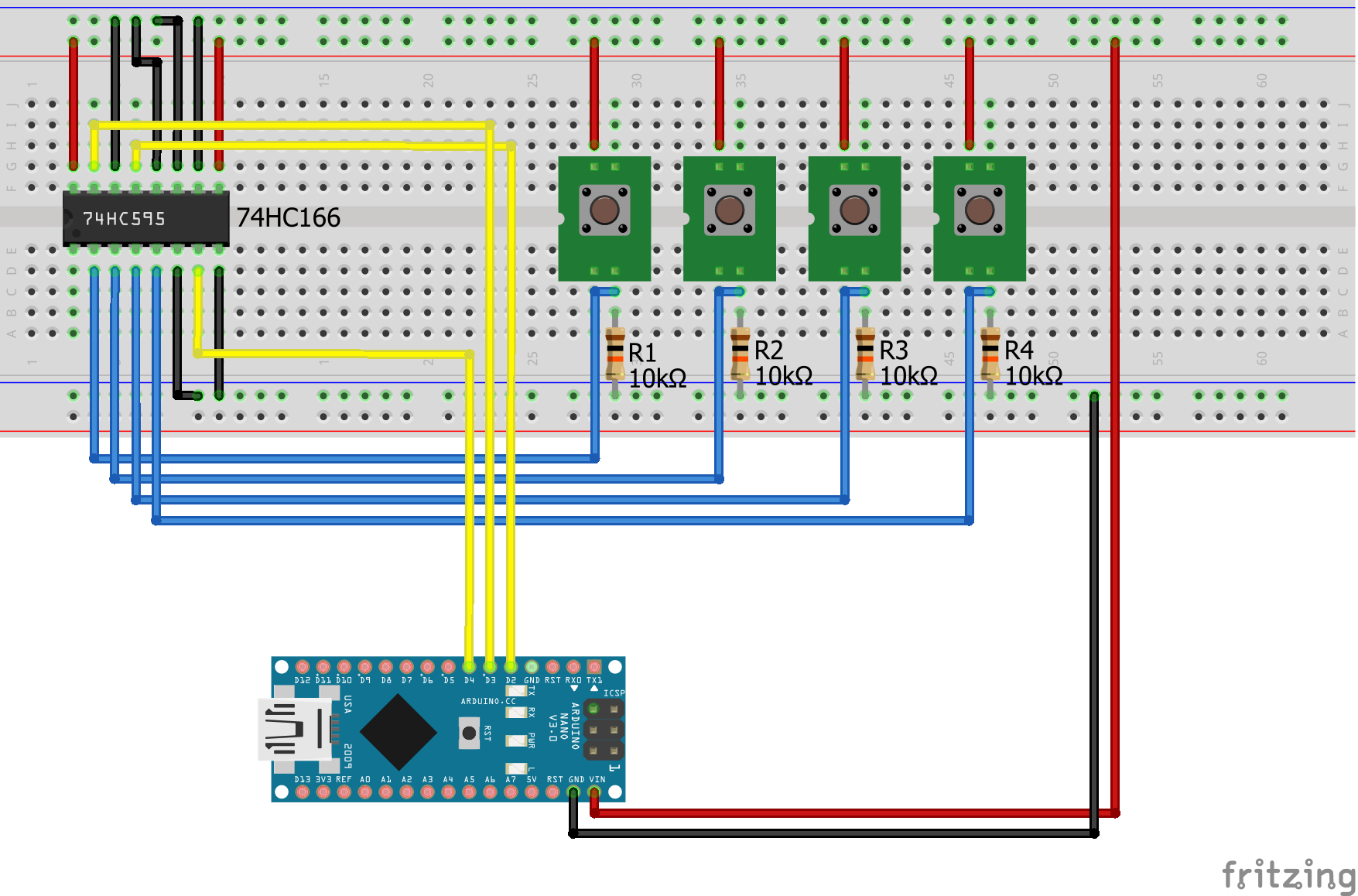
Arduino Shift Register PISO Pull-Down Arduino Uno
Shift Register PISO Pull Down Arduino Mega

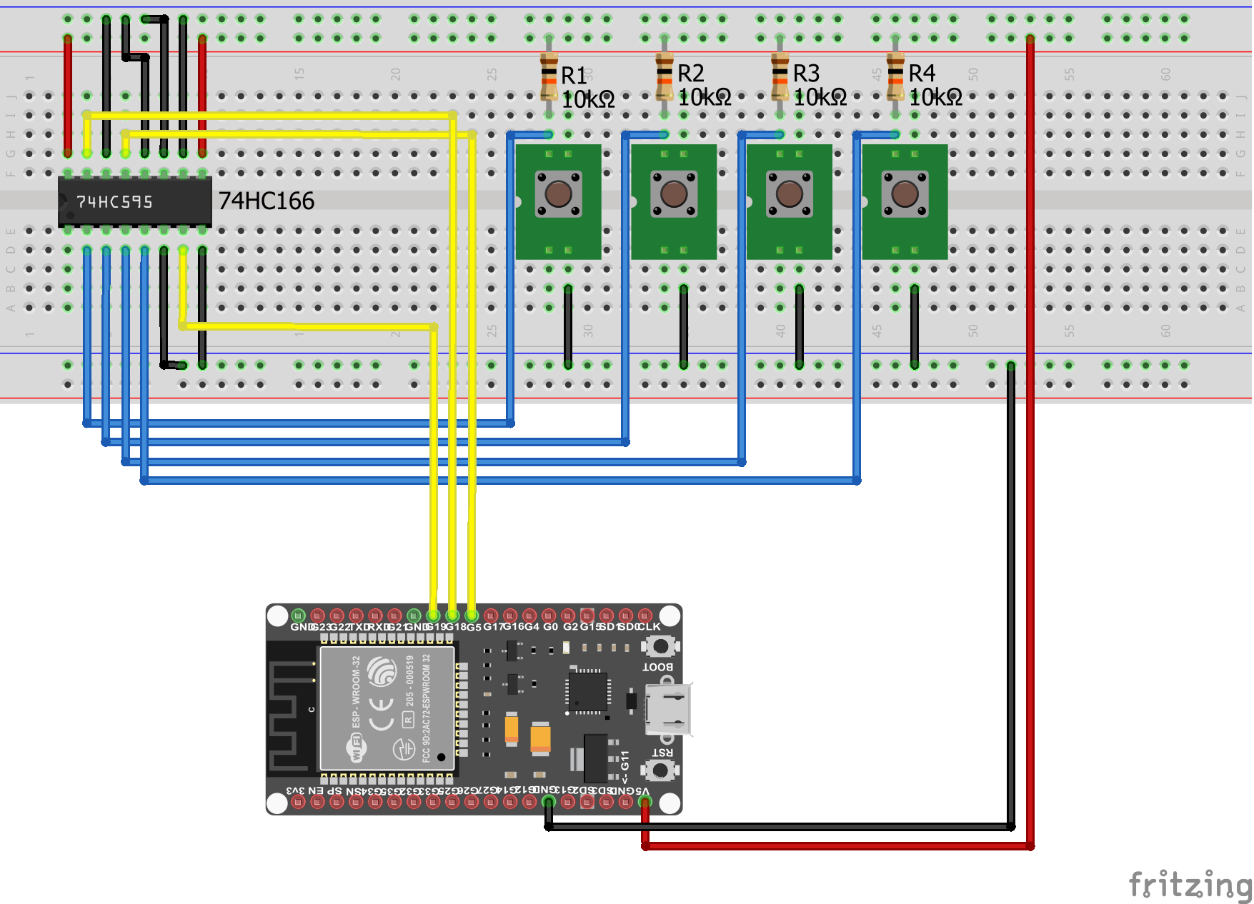
Shift Register PISO Pull Down EPS32 NodeMCU
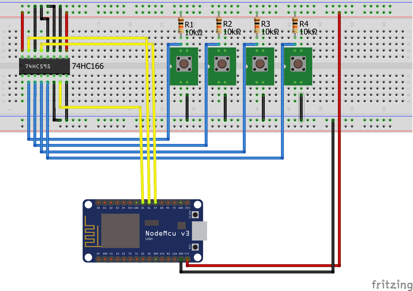
Shift Register PISO Pull Down EPS8266 NodeMCU
Shift Register PISO Pull Down EPS8266 WeMos D1 Mini
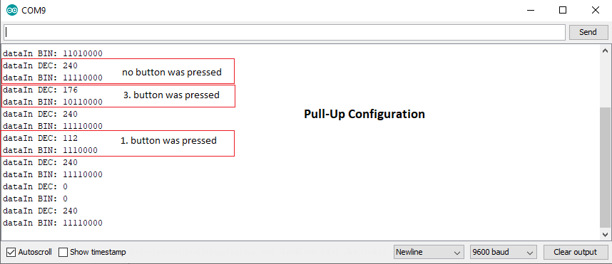
Shift Register PISO Pull Up Arduino Nano
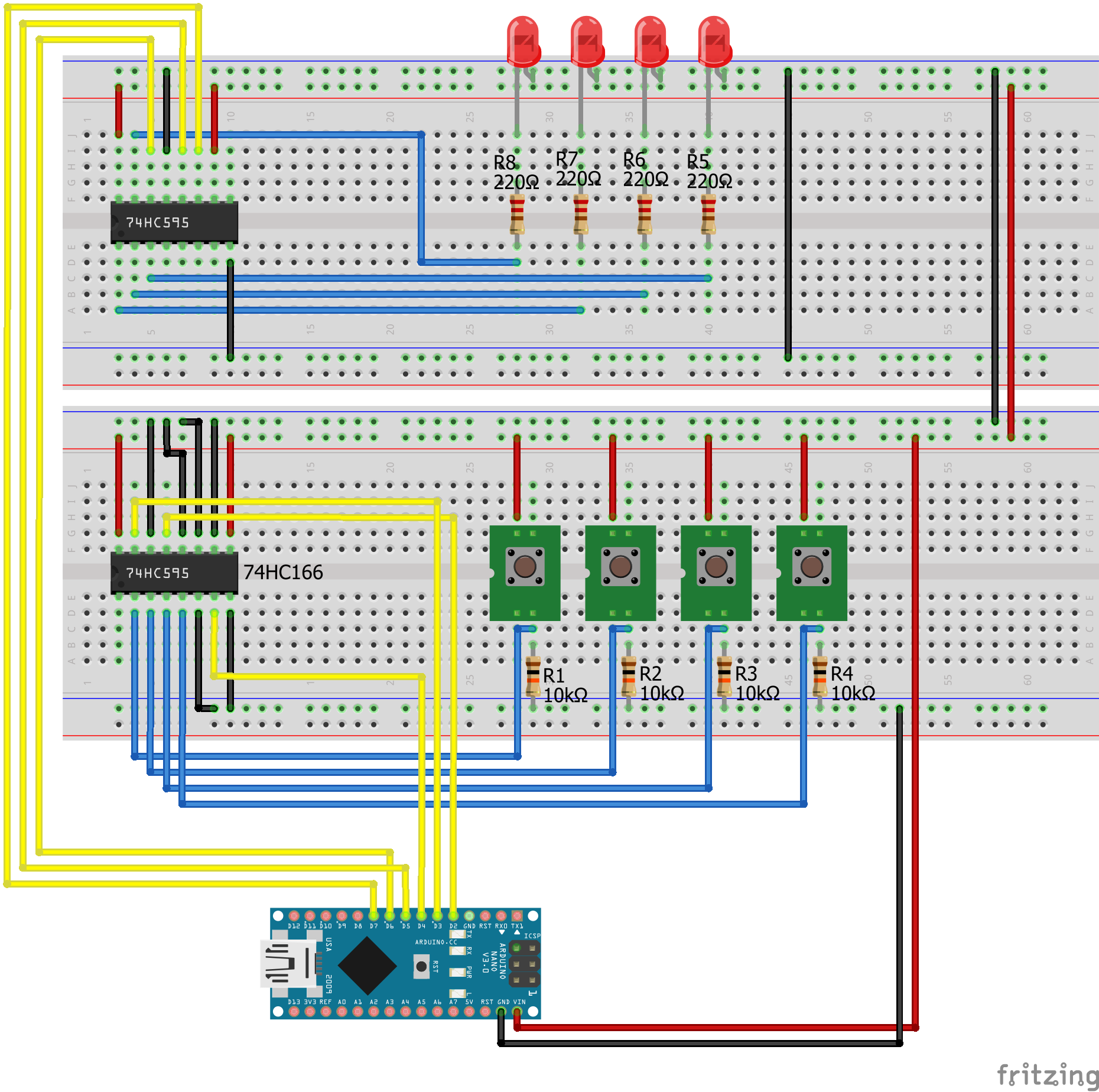
Shift Register PISO Pull Up Arduino Pro Mini
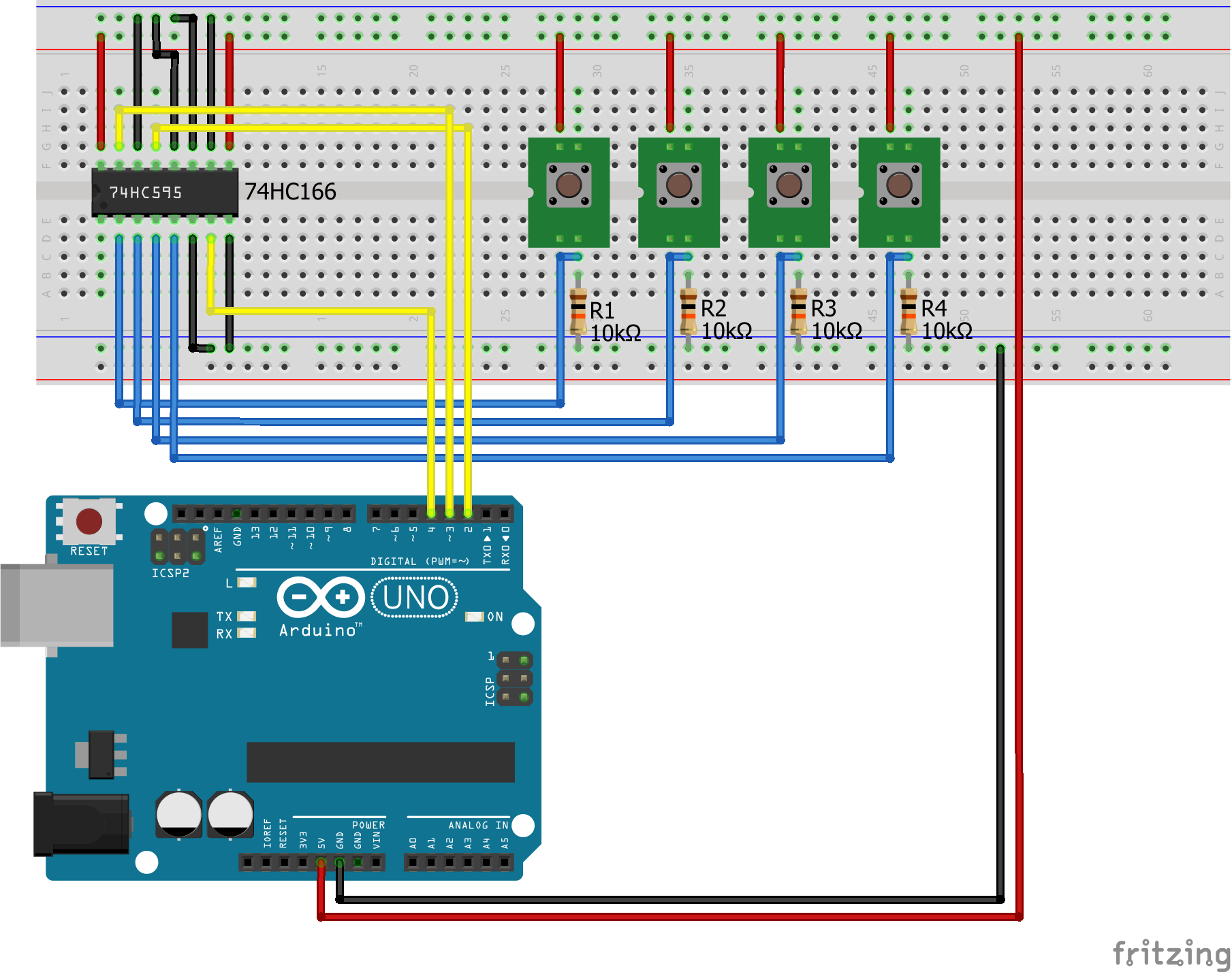
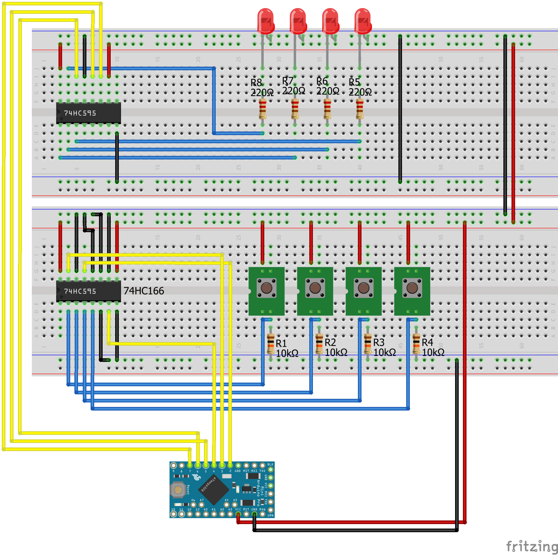
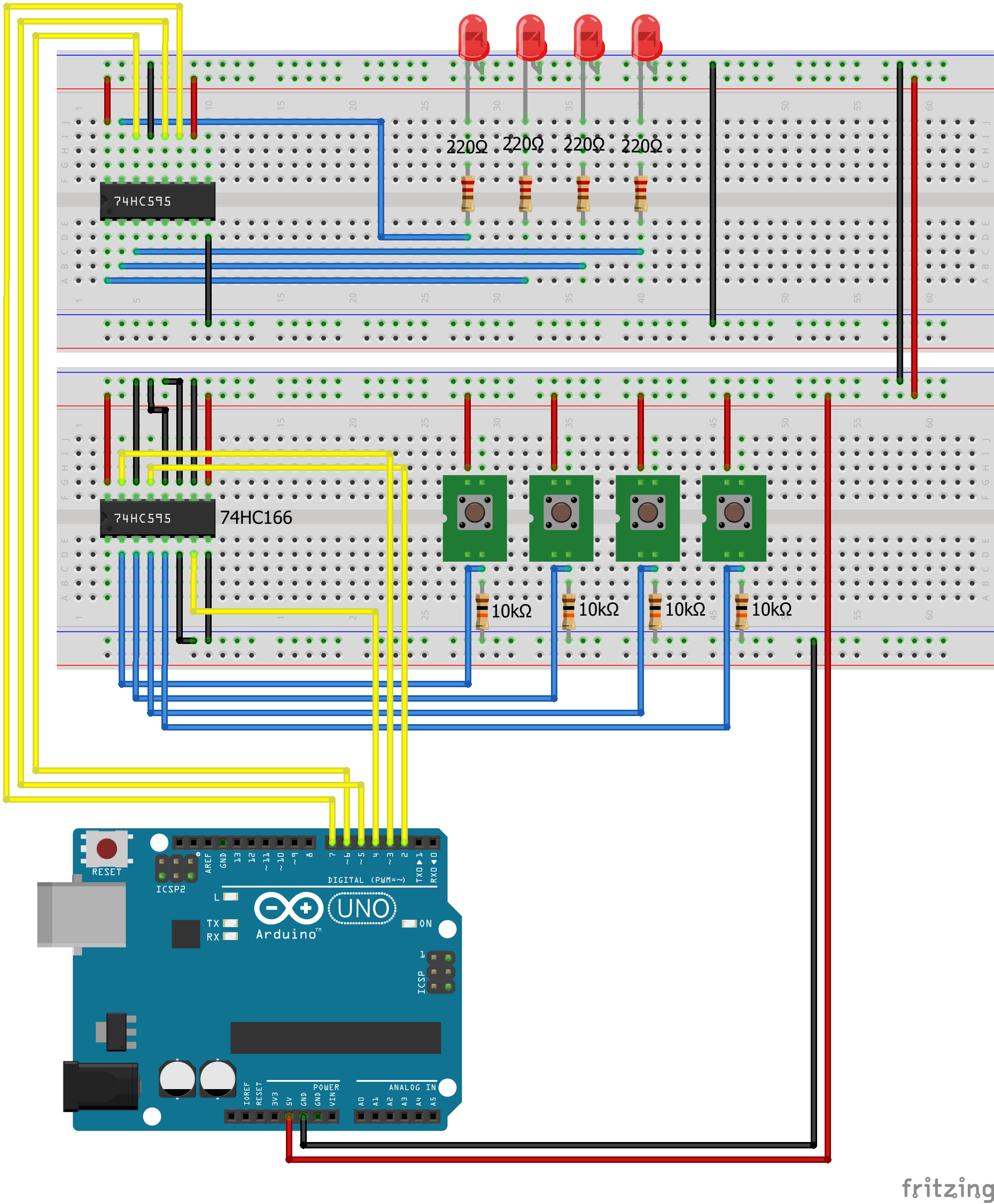
Arduino Shift Register PISO Pull-Up Arduino Uno
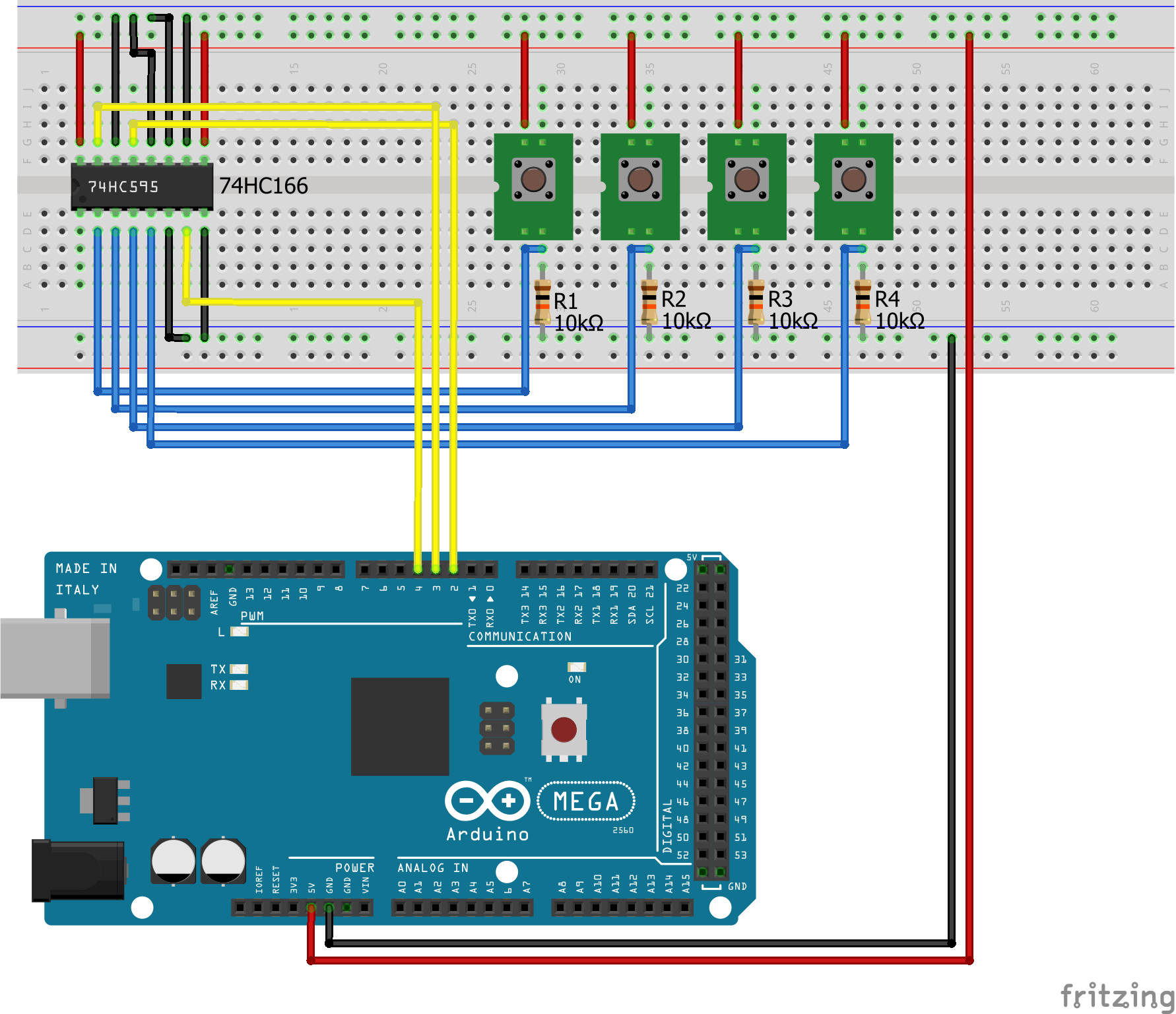
Shift Register PISO Pull Up Arduino Mega
Shift Register PISO Pull Up EPS32 NodeMCU
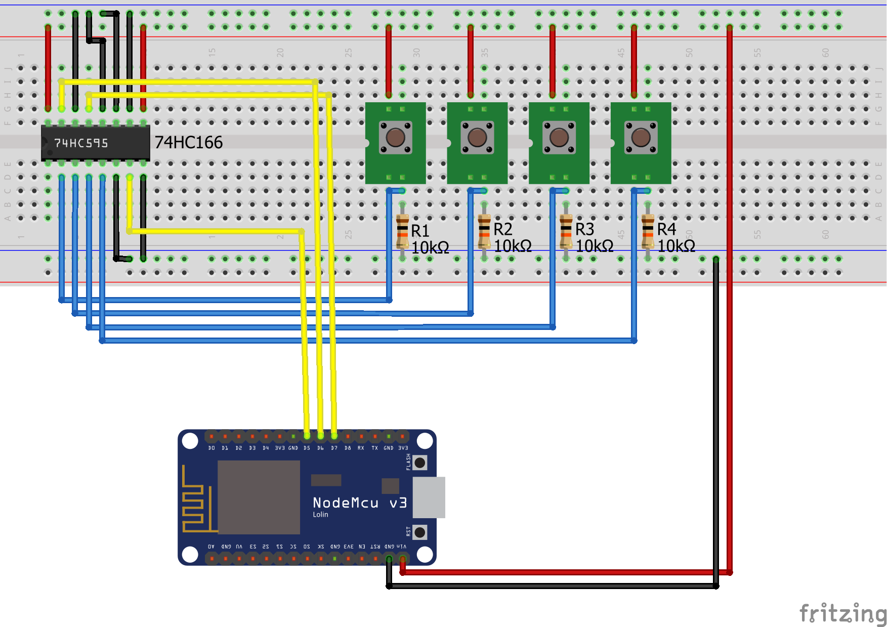
Shift Register PISO Pull Up EPS8266 NodeMCU

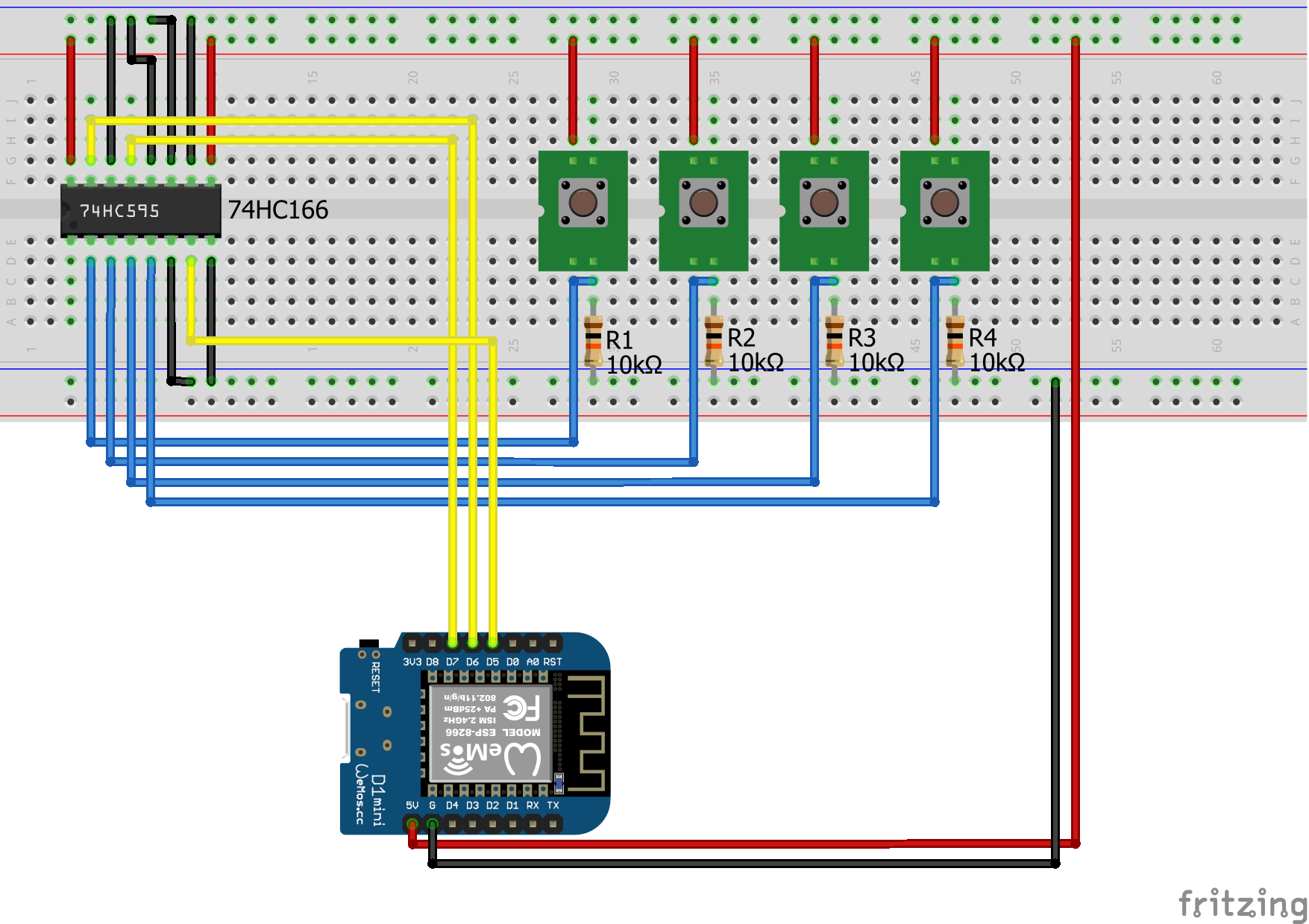
Shift Register PISO Pull Up EPS8266 WeMos D1 Mini
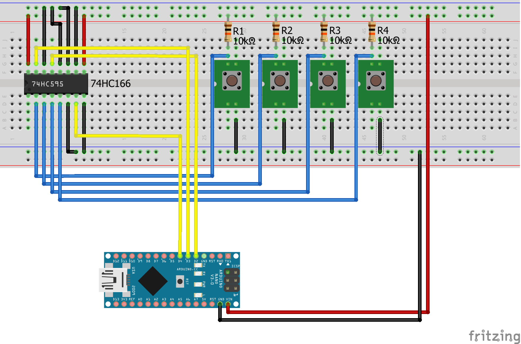
Shift Register SIPO PISO PullDown Arduino Nano
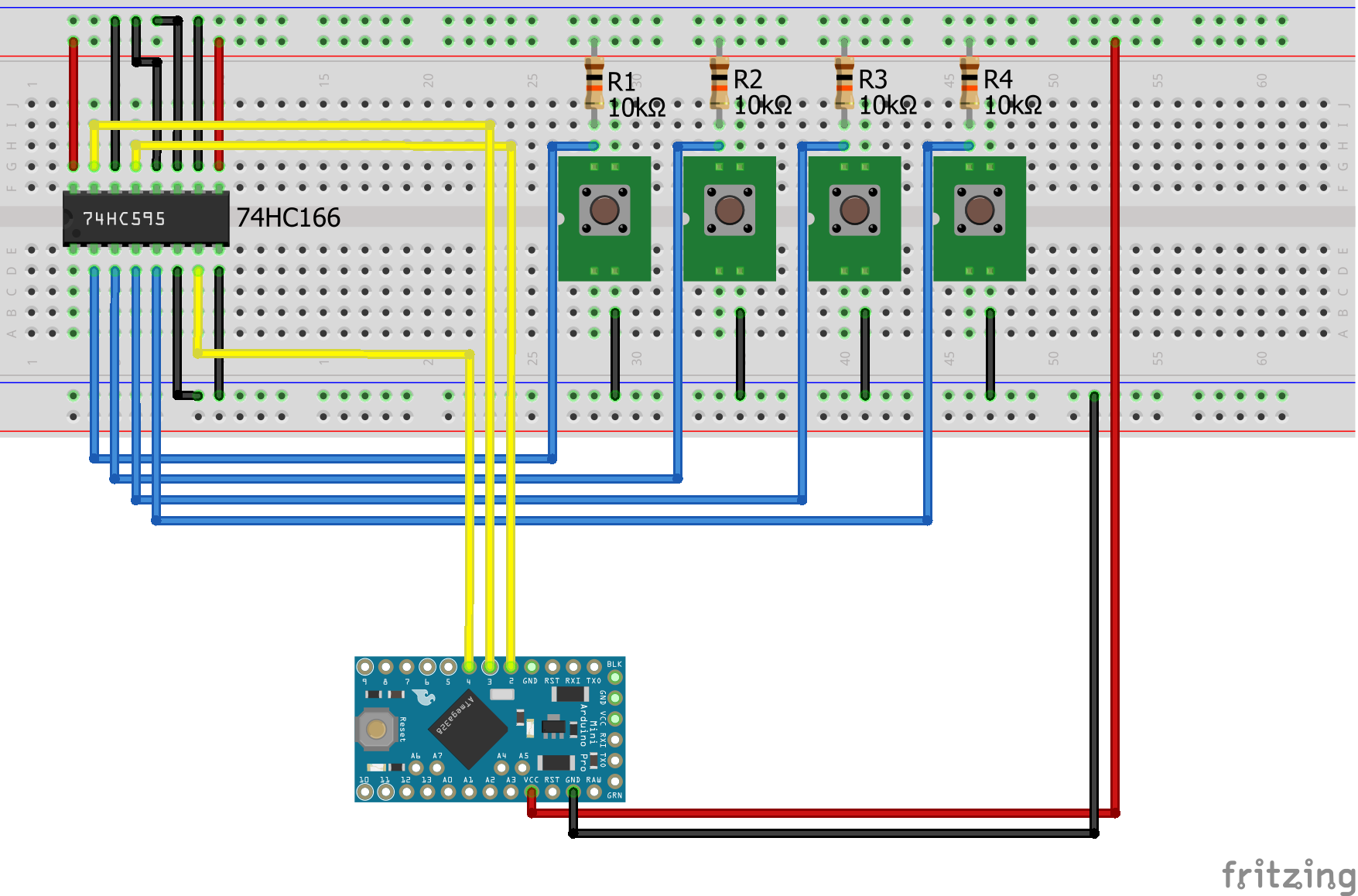
Shift Register SIPO PISO PullDown Arduino Pro Mini
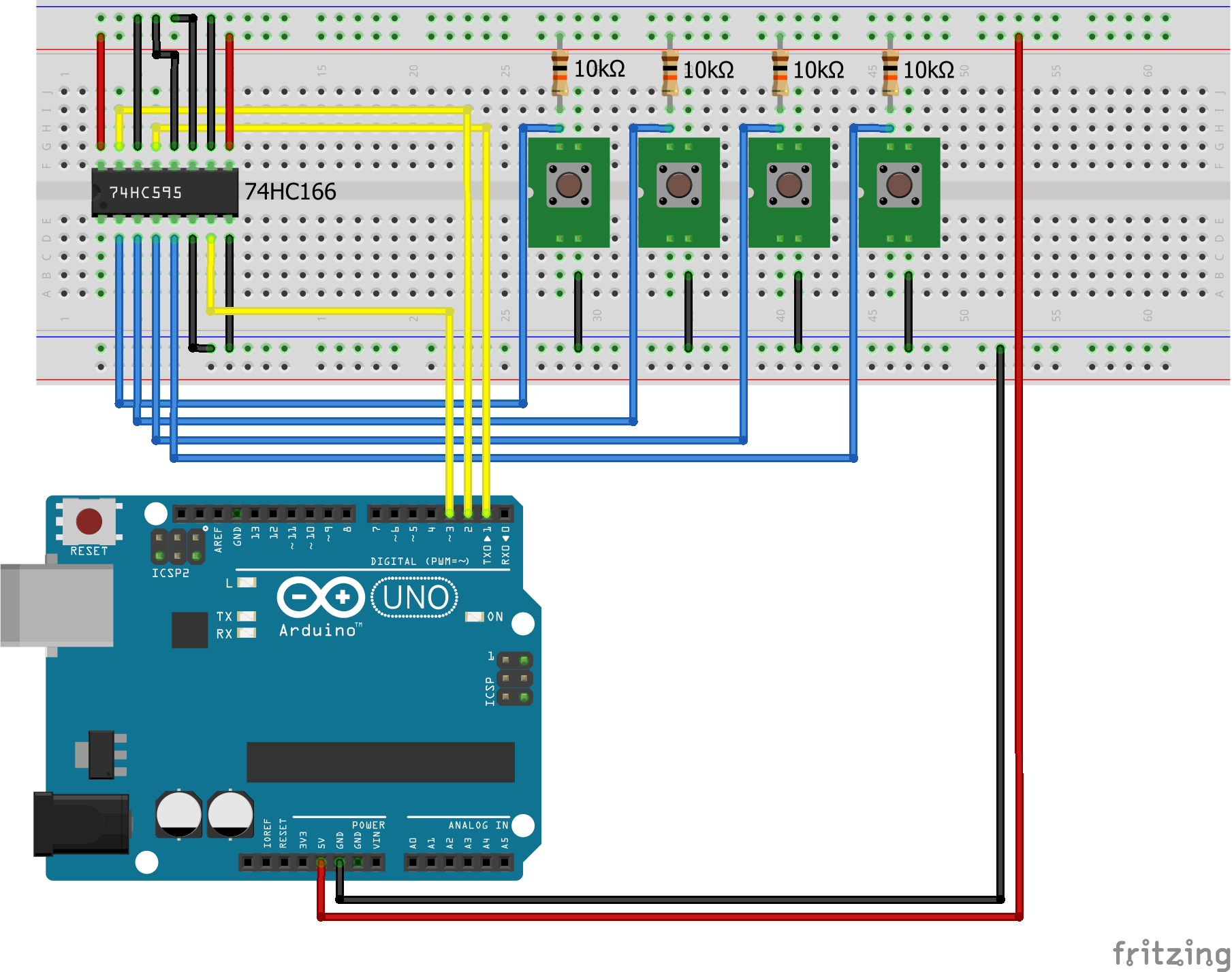
Arduino Shift Register SIPO PISO Pull Down
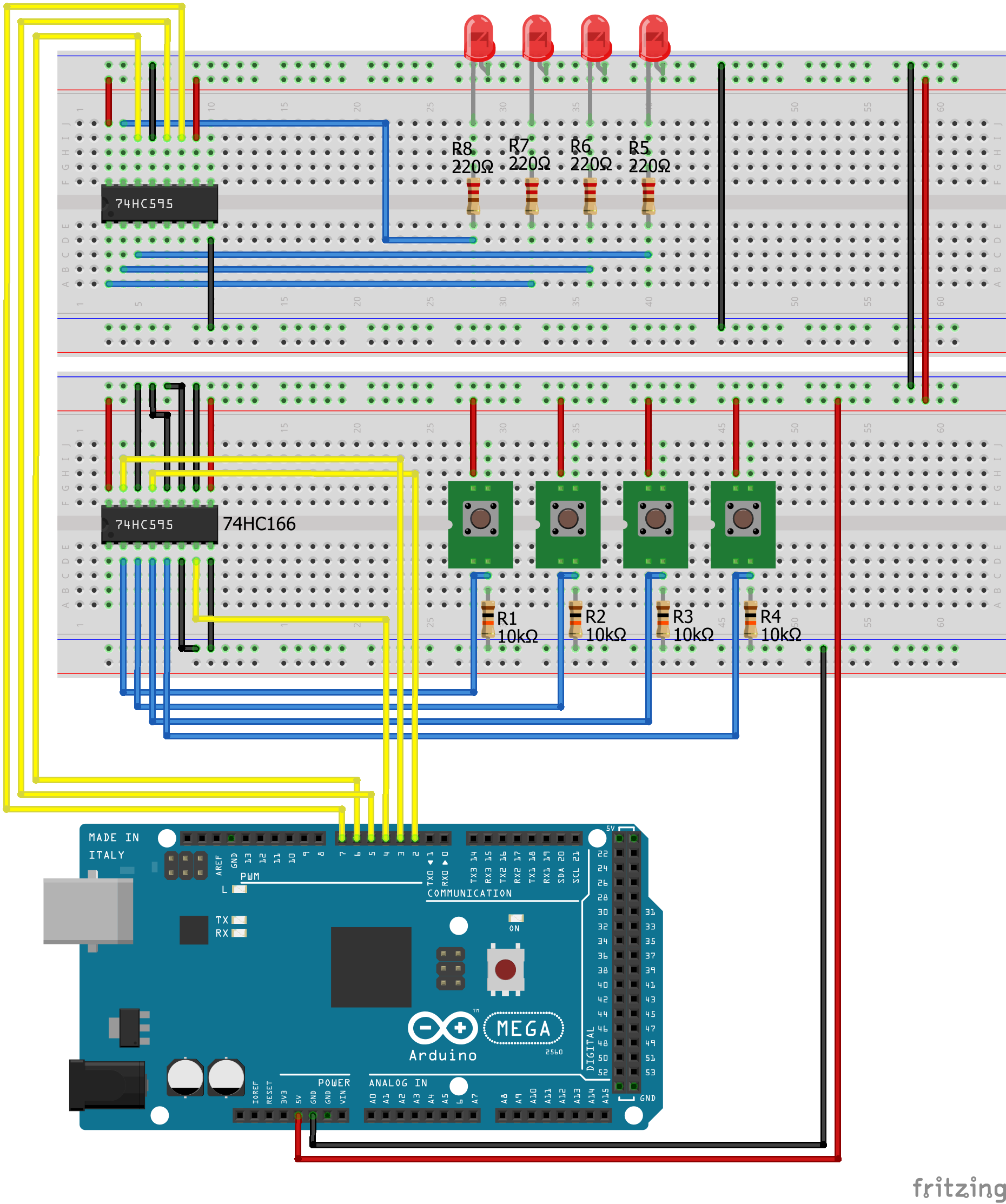
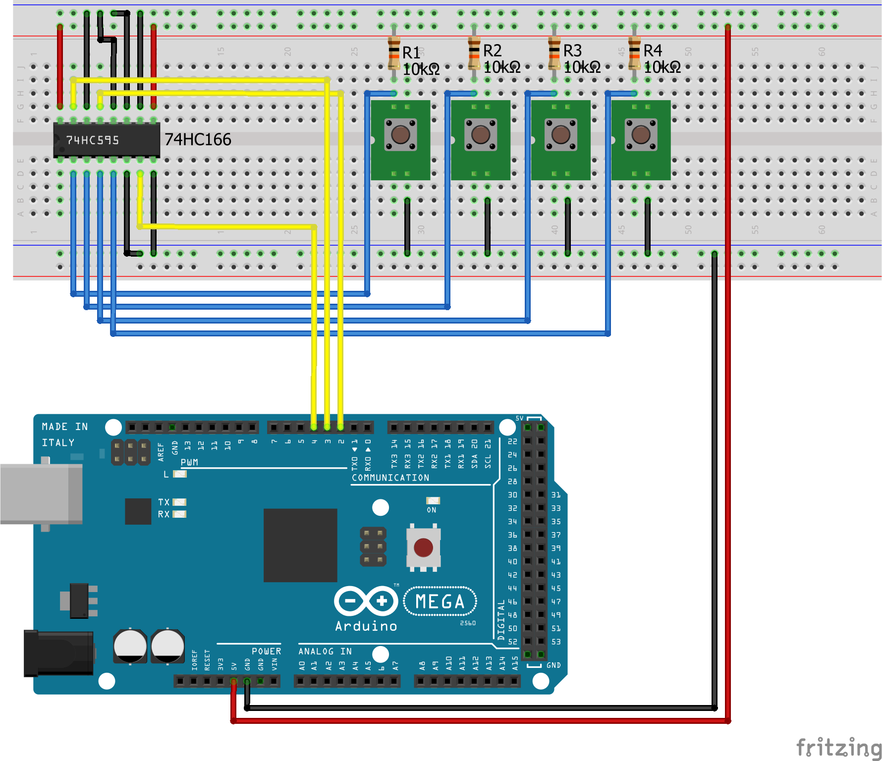
Shift Register SIPO PISO PullDown Arduino Mega
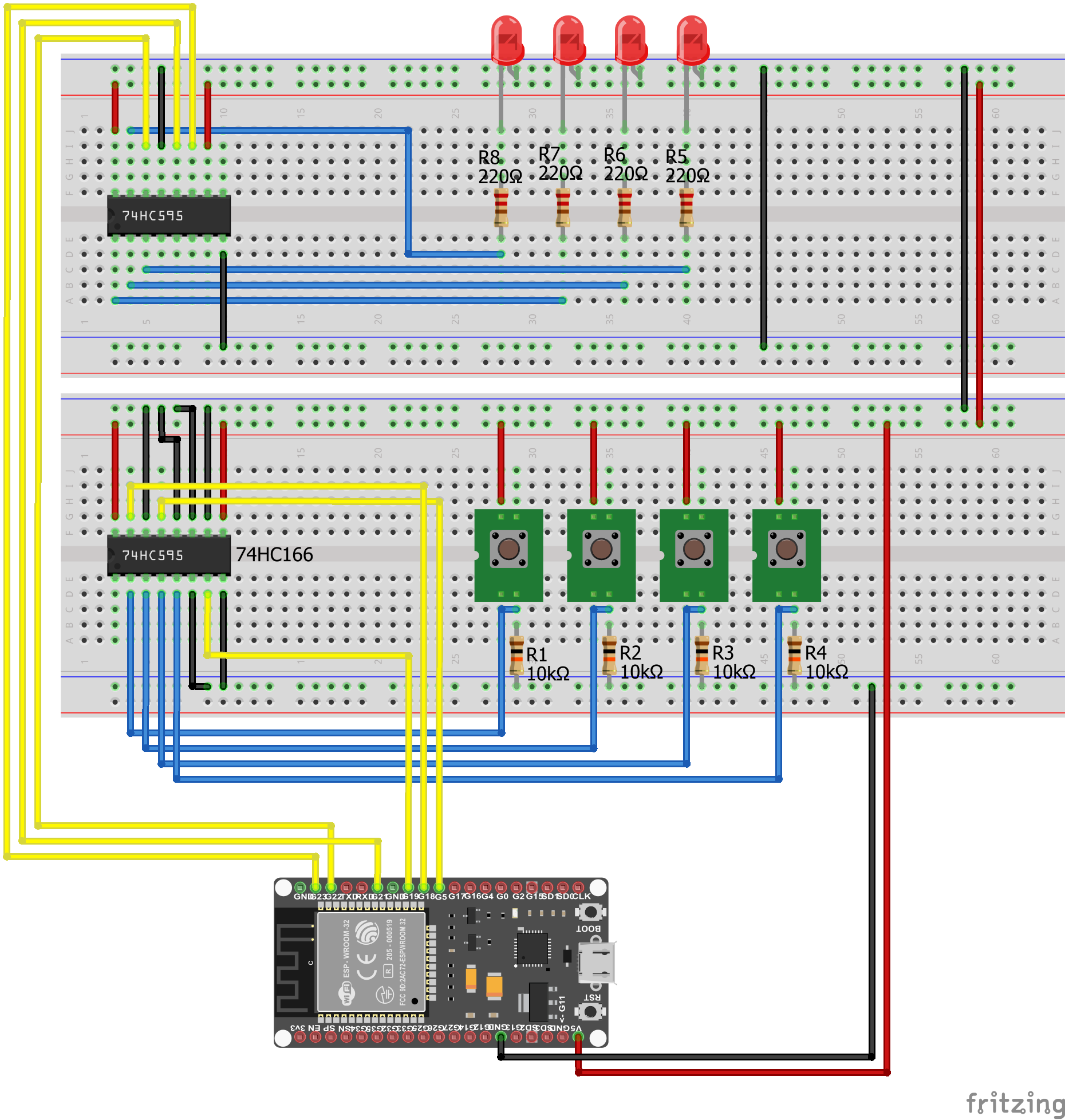
Shift Register SIPO PISO PullDown EPS32 NodeMCU
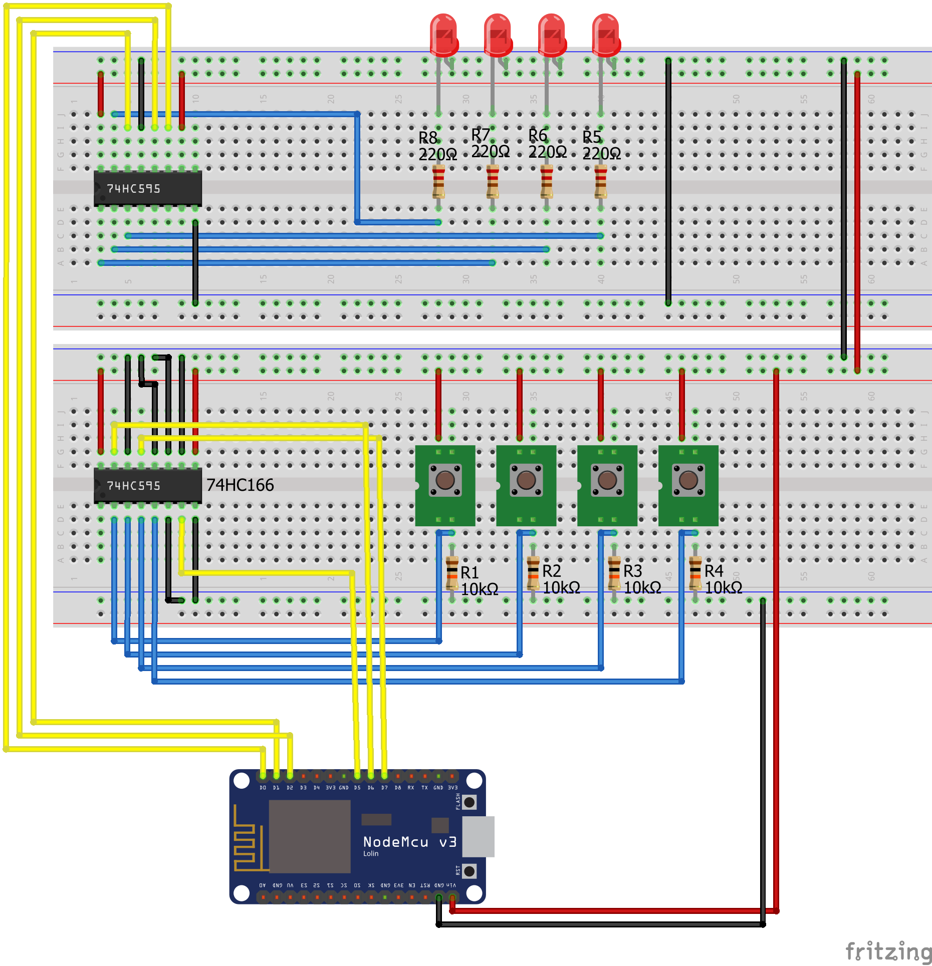
Shift Register SIPO PISO PullDown ESP8266 NodeMCU
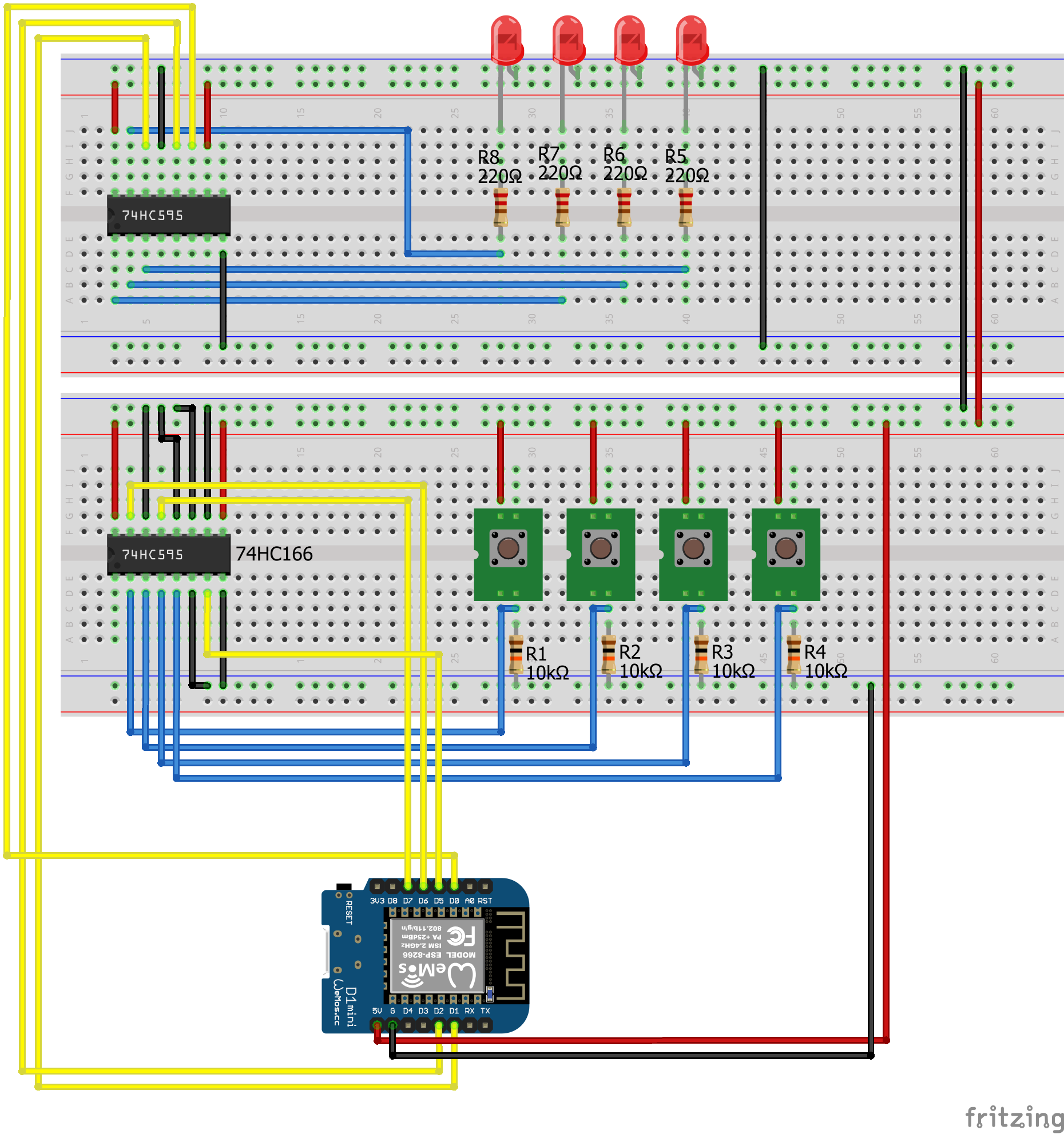
Shift Register SIPO PISO PullDown ESP8266 WeMos D1 Mini
You explanations are very well done.
Looking for an NTP time with the ESP and output to 595 onto four, seven segment LED display.
Keep up the great work.
Hi Za,
thanks for your comment. I will hold the quality high on my blog 🙂
Thanks for the write up. One critical thing on 595N.. As per datasheet, each output pin can only allow 7mA continuously at 1V, or, approximately 3mA at 3.3V (all supply voltage dependent). Therefore, 3-4 LEDs as indicated will not lid.
Hi Deniz,
where did you find this information in the datasheet? On page 6/22 that is linked, I only find the max output current for pins Qn (n: 0…7) is +- 35mA.
Hi where is ESP8266-01 module is not there in images above. My question is could it be used with shift register or not Thankyou
Hi, yes you could also use the ESP-01 as PISO or SIPO because you only need 3 digital I/O pins, see https://diyi0t.com/what-is-the-esp8266-pinout-for-different-boards/
Hi,
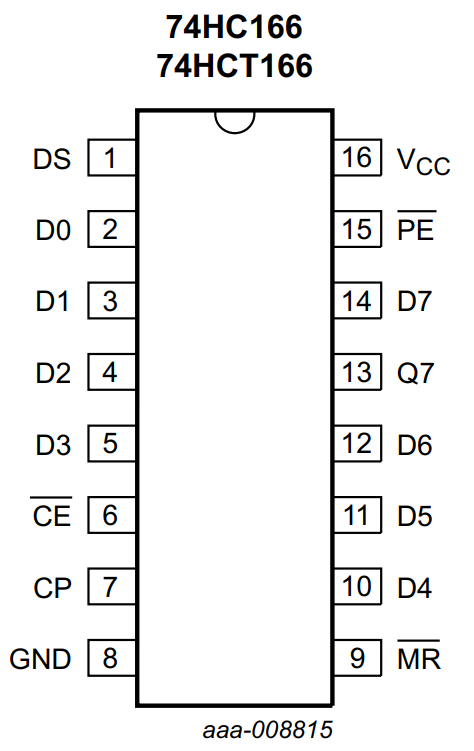
Wonderfully explained. I am working on a cable tester where a Flat Cable with 16 pins needs to be tested for continuity and shorts with Arduino Nano. Your use of SIPO and PISO together is exactly what is needed with SIPO (74HC595) sending HIGH to one end of each wire sequentially of the Flat Cable. The Arduino Nano reads the state of the other end of each wire of the Flat Cable with PISO (74HC166). However, my cable has 16 wires and hence I’ll need cascading 2x 595s and 2x 166s. Do you think this combination of 595 and 166 will suit this application? Can you help me with the code to synchronise the sending of sequential HIGH to one end and reading the state of the other end?