Increase the Number of Analog Inputs with an Analog Multiplexer
One of the most used micrcontroller in my DIY projects is the ESP8266. But all ESP8266 boards like the ESP8266 NodeMCU or the WeMos D1 Mini have one mayor downside:
They have only 1 analog input pin.
But you can increase the number of analog inputs with an analog multiplexer. In this tutorial I show you how to increase the number of analog inputs to 4, 8 or 16 with an analog multiplexer.
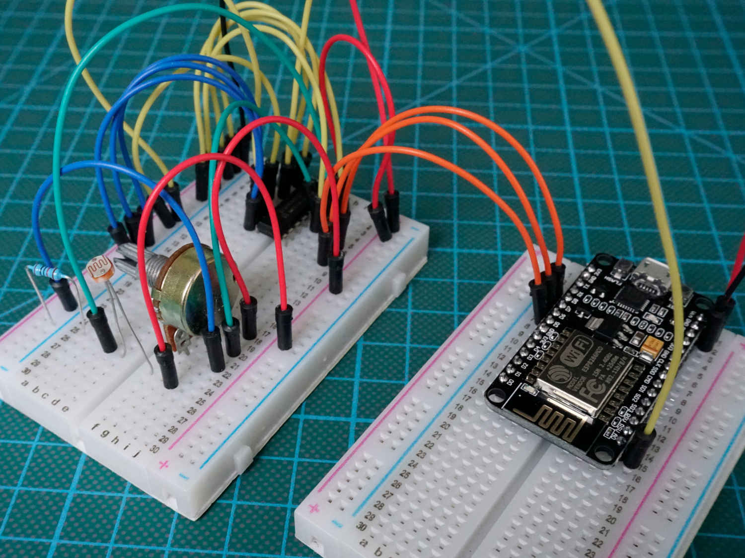
Table of Contents
Function of a Multiplexer
In my opinion the best explanation of a multiplexer is a big switch which connects all inputs with one output. Which input is connected to the output is defined by the state of the select lines pins.
Because only one input is connected to the output, all other lines loose the connection. This is important because devices that require a continuous signal (like a servo motor) will not work in combination with a multiplexer.
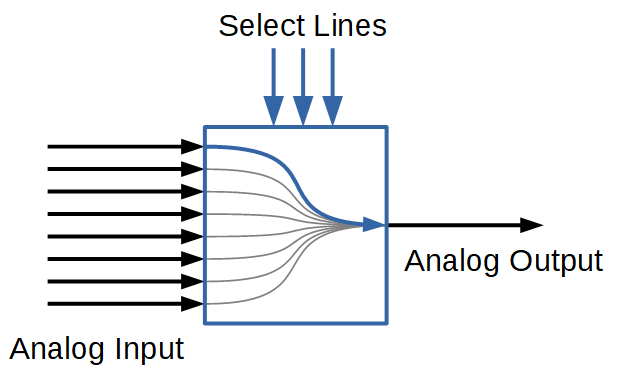
A multiplexer of 2^n inputs has n select lines which is shown in the following table.
In this tutorial I use the CD74HC4051 analog multiplex from Texas Instruments
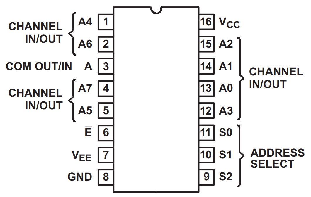
74HC4051 Data Sheet and Pins
Before we start with the practical example, let us quickly summarize the data sheet of the CD74HC4051.
The 74HC4051 is an 8 bit analog multiplexer / demultiplexer and therefore build up with bidirectional switches that allow any analog input to be used as an output and the way around.
The most important value is the maximum input voltage with is 5V for the analog multiplexer. The 5V fits well with all Arduino and the EPS8266 based microcontroller. You find the whole data sheet here.
The functionality of the CD74HC4051 as analog multiplexer is easy explained in two steps:
- The multiplexer gets the select line signal from the 3 digital outputs of the microcontroller.
- If the enable state is set to LOW, the corresponding analog input (A0…A7) is connected with the analog output (A)
The following table shows the input states of the CD74HC4051 and the corresponding analog output channel.
Increase the Analog Inputs on the ESP8266
In the following example we increase the number of analog inputs of the ESP8266 NodeMCU and WeMos D1 Mini, which have only one analog input pin. The analog inputs I choose are:
- 1 photoresistor
- 1 potentiometer
But you can choose any other analog device.
The following pictures show the wiring between all components and the ESP8266 microcontroller.

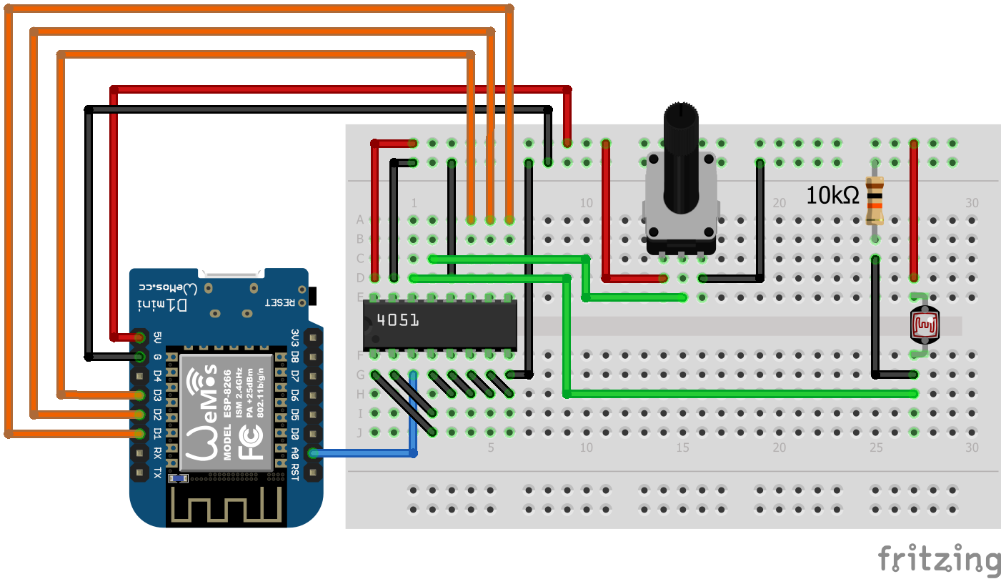
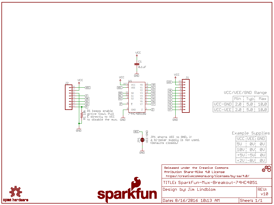
The photoresistor is connected to the 74HC4051 via a voltage divider with a 10kΩ resistor on pin A1. The potentiometer is directly connected to the multiplexer on pin A0. All other analog pins are connected to ground. Moreover the pins VEE and E are also connected to ground. The address select pins are connected to the ESP8266 like the following:
- S0 -> D3
- S1 -> D2
- S2 -> D1
Now lets dive in to the program code.
const int selectPins[3] = {D3, D2, D1};
const int analogInput = A0;

void setup()
{
  Serial.begin(9600);
  // Set up the select pins as outputs:
  for (int i=0; i < 3; i++)
  {
    pinMode(selectPins[i], OUTPUT);
    digitalWrite(selectPins[i], HIGH);
  }

  // Create header table
  Serial.println("Y0\tY1\tY2\tY3\tY4\tY5\tY6\tY7");
  Serial.println("---\t---\t---\t---\t---\t---\t---\t---");
}

void loop()
{
  // Loop through all eight pins.
  for (byte pin=0; pin <= 7; pin++)
  {
      for (int i=0; i < 3; i++) {
          digitalWrite(selectPins[i], pin & (1 << i)?HIGH:LOW);
      }
      int inputValue = analogRead(analogInput);
      Serial.print(String(inputValue) + "\t");
  }
  Serial.println();
  delay(1000);
}
First we have to define the connected pins. As mentioned before we connected the 3 digital pins D3, D2, D1 as well as the analog input A0. For the digital pins we create an array to loop through the pins easily during later stages in the code.
In the setup function we first set the baud rate to 9600 which must match to the rate in the serial monitor. Then we loop through the selectPins array and set every digital pin as output
The last part of the setup function is more an optical preference. We create a virtual table in the serial monitor by setting a tabulator space between all possible 8 analog values.
In the loop function we loop over all 8 possible analog pins and set the select pins HIGH and LOW with a little bit confusing formula. But the following table shows all the different combinations to get the selected pins set correct.
We calculate the state of each select pin in 3 steps:
- 1<bit-shift of each 3 select pins
- pin & (1<<i): bitwise AND with the selected analog output which should be selected
- pin & (1<<i)?HIGH:LOW: calculate the ternary conditional which is in this case very easy. If pin & (1<<i) is 0, then set the condition to LOW and otherwise HIGH.
After we set the select pins, the analog multiplexer is configured to read the desired output. We read the analog value with the build in function analogRead and print the value to the serial monitor. Each value is separated with a tabulator like the header we created in the setup function.
Now the program is reading all analog input values. In the following picture you see a screenshot of the serial monitor
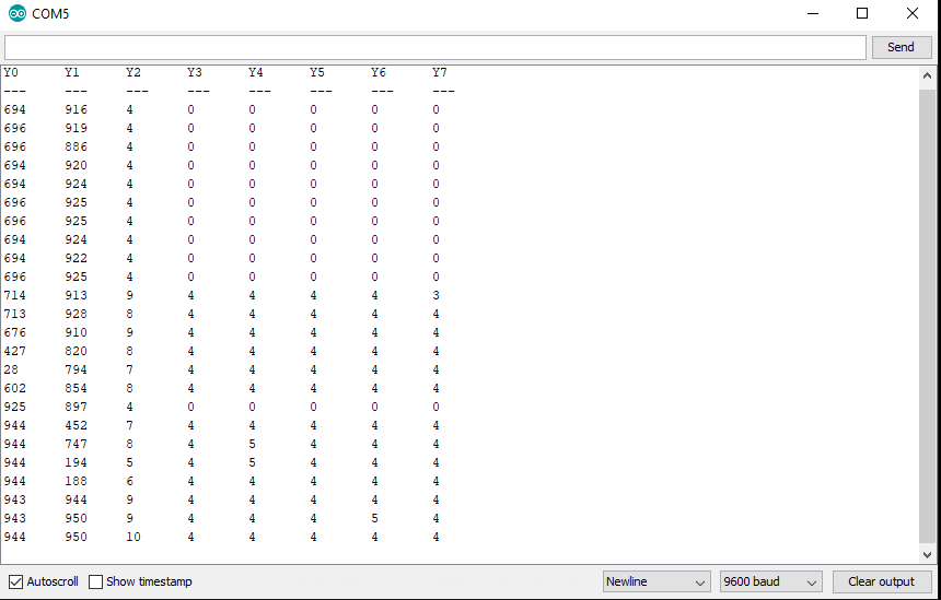
The first value Y0 is the potentiometer. You see from the picture that I increase and decrease the resistance and therefore the analog value. The second value Y1 is the photoresistor which I influence by holding my hand on it to make it dark and change the analog value.
One thing that surprises me is that all other analog values Y2…Y7 are not always 0 although I connected all other analog input pins on the multiplexer with ground. My assumption is that there are some back coupling between the analog signals but I do not know how to remove the noise in the analog signals which are connected to ground. If you know why the other analog values are not zero, write your suggestion in the comment section below.
I also installed a decoupling capacitor between VCC and ground on the 74HC4051 because I saw this circuit for the sparkfun 74HC4051 multiplexer breakout board. But after the installation of the decoupling capacitor there was no change in the serial monitor.
In my opinion, either you know which analog signals from the multiplexer are connected and only read for example the first three or you can set a threshold > 10 to read all analog signals.
I hope you like this tutorial how you can increase the analog inputs on your ESP8266 NodeMCU or WeMos D1 Mini for your next project. If you have any questions you can use the comment section below and I will ask your questions as soon as possible.
If you are also interested how to increase the number of digital outputs with a shift register, then I can recommend this article.
Incredibly informative look onward to visiting again.
I am glad that you enjoyed reading the article
nice tutorial
Hi Thomas,
nice that you liked the tutorial.
Simply want to tell you I’m happy that i happened onto your web page!
Hi, nice to hear that the post helps you to increase your number of analog inputs 🙂
Wow! thanks a lot! just what i been looking for!
I’ve just changed “const int selectPins[3] = {D8, D7, D6};” to const int selectPins[3] = {D3, D2, D1};” on my code and it works great!
I am using NodeMCU amd i want to connect different gas sensors
And all the gas sensors have analog outputs, so by using the above logic, can i interface those sensors with nodemcu
Hi Jayank,
yes you can read up to 8 analog inputs on your ESP8266 NodeMCU with the analog multiplexer.
Can I use the multiplexer as a relay? when I select certain input signal with the select lines , it will appear on the output? do I need to have an analog singal or even if there is no signal a hard wire will be between the input and the output?
Do you mean that you want to have not only multiple analog inputs but also analog outputs? Only the ESP32 has two build in digital-to-analog converters but for the ESP8266 and Arduino, there are options with an IC.
Hii.. May i ask, why is that my serial monitor gives all values the same? (all 9 to 10 for all pin). Did the wiring exact like the schematic, however potentiometer or any other is not detecting. Is it code/wiring/board problem? Been having these slump for days already.. Thanks..
🙁
Hi Mus,
you can try not to use a potentiometer or other electronic devices but to connect one analog pin either to ground or to the 3.3V pin of the NodeMCU. The value should be switching to 0 or 1023 which is the minimum and maximum value of the analog input.
If this does not work and you are sure that you connected all wires like in my example, it has to be a code problem or you have to try another 74HC4051
Hi, I’ve already tried this one and it works. thanks a lot. may I ask something about using two 74HC4051 in NodeMcu which can control analog and digital? could it possible?
Hi Ica,
do you mean 1x 74HC4051 for analog values and 1x 74HC4051 for digital values? That is not possible because the 74HC4051 is only for analog values. For digital values you can use a shift register like in this article: https://diyi0t.com/shift-register-tutorial-for-arduino-and-esp8266/
Good day! I am so glad I found this tutorial. Question: You mentioned that the VIN pin on the ESP8266 NodeMCU is a 5V output, however, I have tried it with 4 different ESP8266 NodeMCU’s I have, but I only measure anything between 0.9V and 2.9 Volt. The ESP32 Dev Kit C, however outputs 4.6 Volt on its VIN pin. I am using a charger cable from my laptop USB to power up the NodeMCU. Am I missing something? Kind regards