UART Tutorial for Arduino and ESP8266
In this tutorial we dive deeper into the universal asynchronous receiver-transmitter short UART.
You learn the following parts:
- Protocol Settings
- Data Transmission and Framing
- Advantages and Disadvantages
At the end of this tutorial you find a step by step example of the UART communication between an Arduino Uno and an ESP8266 NodeMCU
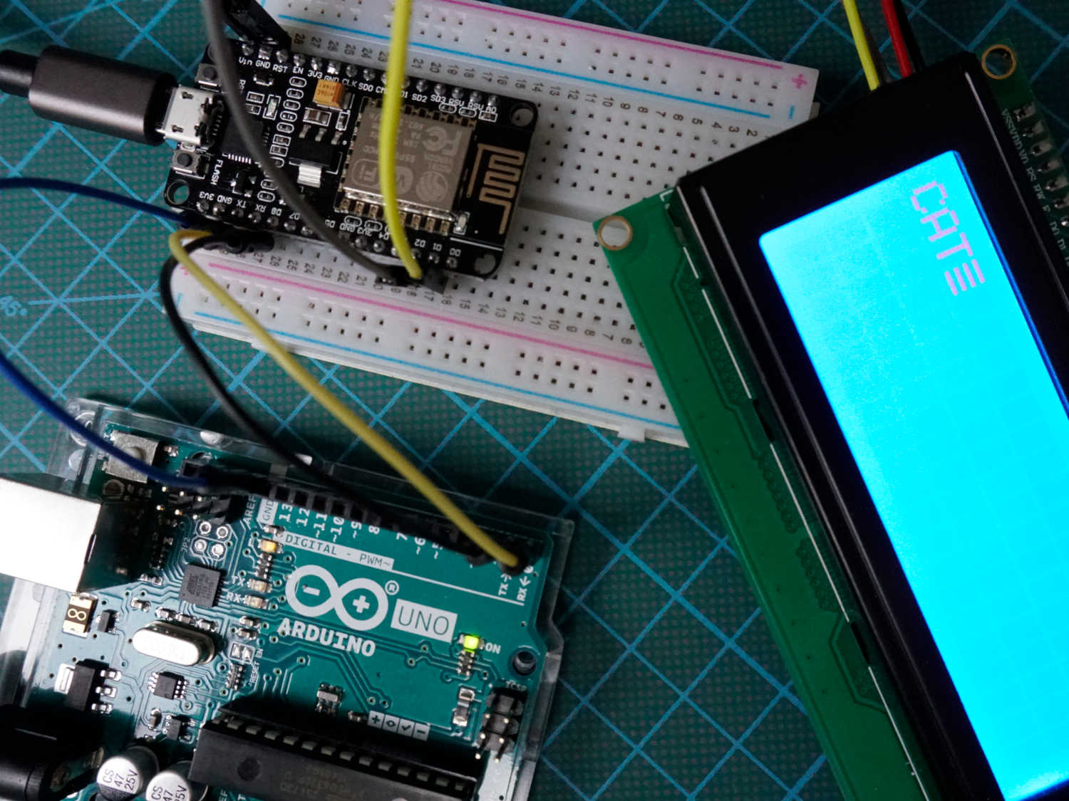
Table of Contents
UART is the only asynchronous serial communication protocol and used in RFID card reader modules as standalone communication interface. But UART is typically more found inside microcontrollers.
Compared to I2C and SPI, UART is the oldest communication protocol, invented 1960 by Gordon Bell at Digital Equipment Corporation.
The following table compares the communication protocols I2C, SPI and UART based on different categories.
The mayor drawback of UART is that no multiple master and no multiple slave communication are supported. Therefore there are always 1 master and 1 slave device.
Because the data transfer is asynchronous, UART does not need a clock signal to synchronize data transfer and data can be send and received in different timings. If master and slave device send and receive data at the same time, called full-duplex communication, each device need 2 shift registers to store the transmitting and receiving characters. This is necessary because a device could receive a new data byte while still sending a data byte.
In comparison in SPI communication, master and slave only need 1 shift register for the receiving signals because due to the synchronous data transfer the shift register is emptied and filled at the same time and because the size of the shift register is the same for all devices the data transfer starts and finished at the same time.
In addition to the full-duplex communication, there are two more communication forms which only need 1 shift register:
- simplex: one direction with no provision for the receiving device (fire and forget)
- half duplex: devices take turn transmitting and receiving
UART Settings
In most applications the least significant bit is transmitted first. To prevent data loss hat high transmission rates, many UART devices have a small fist-in, first-out (FIFO) buffer memory between the shift register and the host system.
The clock frequency is typically 8 or 16 times the bit rate. The receiver tests the state of the incoming signal with the clock frequency. If the start bit least more than half the bit time, the receiver detects the valid start bit. Otherwise the start bit is ignored. The clock frequency also called baud rate is typically set to 9600 bits per second
Data Transmission and Framing
One advantage of UART is that only 2 wires are needed for the communication between master and slave device, because there is no need for a clock line and like SPI communication, there is also no slave select line. The 2 lines are:
- TX (transmission)
- RX (reception)
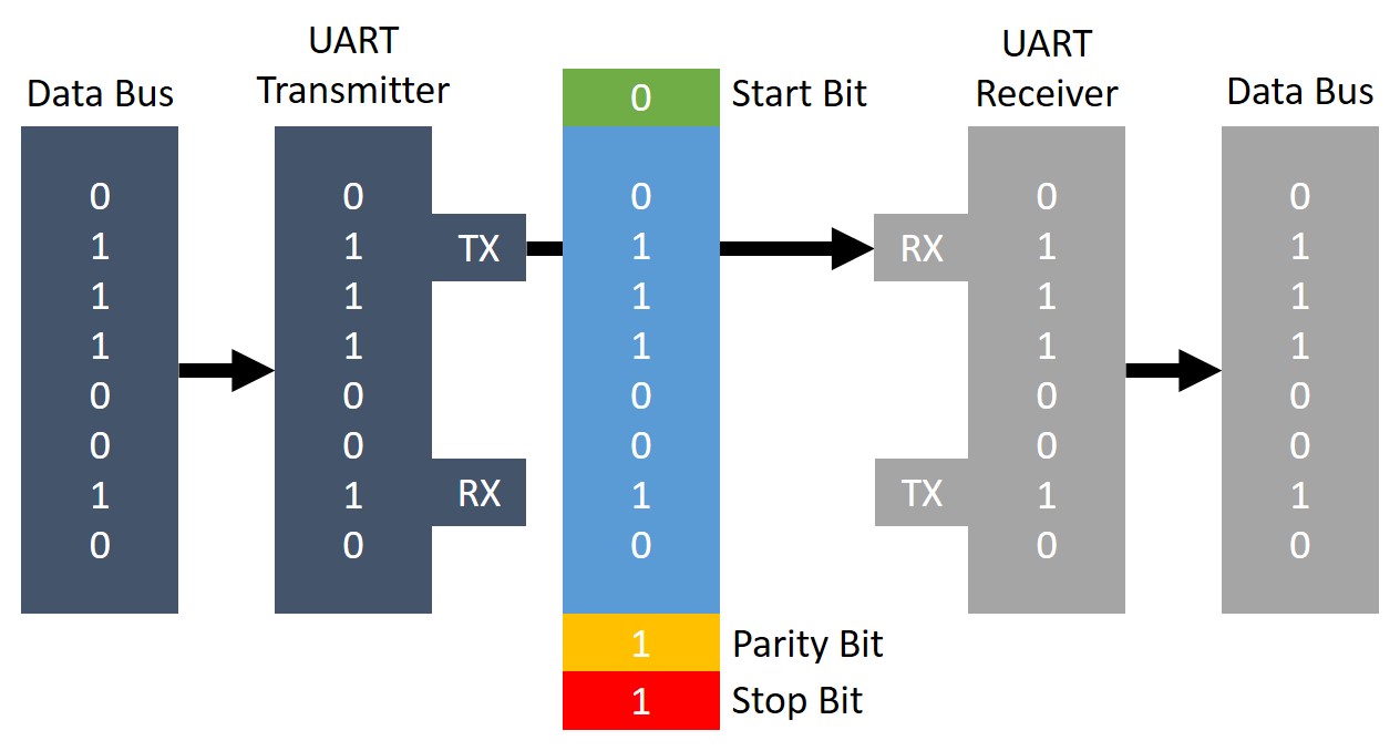
From the picture above you see that the lines are crossed so that TX and RX are connected between the devices.
First the device which transmit the data receives the data frame in parallel from data bus. The UART device adds the start bit, parity bit and stop bits to the data frame before the whole data package is send via UART to the receiving device. The receiving UART device extracts the data frame and forwards the data frame in parallel via data bus.
The following picture and description gives a deeper explanation into the framing processes during the UART communication.
If no UART communication is active, the idle state on the communication lines is logical HIGH because in the time of telegraphy a high lend line shows that the transmitter is not damages.
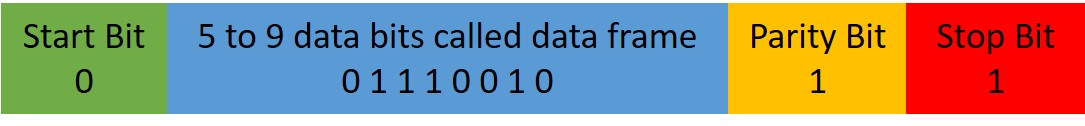
The start bit is the first bit that is transferred as logic LOW, signals that a new character is transferred.
After the start bit follows the actual data frame which data format and size is configurable between 5 to 9 bits.
After the data frame follows an optional parity bit which gives UART the possibility of error checking. The parity bit is 0 if the sum of 1 bits in the data frame is even and 1 if the sum of 1 bits in the data frame is odd. This error checking method prevents from changing bits during the transfer.
The last bits are reserved as stop bits and signal that the character is complete. Therefore the stop bits pull the line HIGH
If the communication is finished and should be ended, the master set the line to logic LOW longer than a character time. This indicates the slave that the UART communication is finished.
UART Advantages and Disadvantages
Advantages
- UART uses only 2 wires for the communication
- There is no extra clock signal line needed
- Error checking is possible due to the parity bit
Disadvantages
- The size of the data frame is limited to 9 bits
- There is no support for multiple-master or multiple-slave communication
UART Communication between Arduino and ESP8266
The following table gives you an overview of all components and parts that I used for this tutorial. I get commissions for purchases made through links in this table.
In the following example we want to send a string from an Arduino Uno to a ESP8266 NodeMCU via the UART communication line and display the string on an LCD screen.
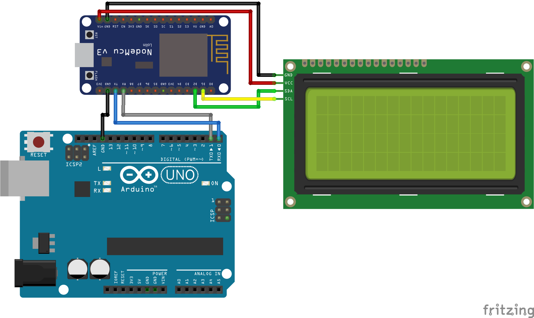
The following picture shows the connection between the Arduino and ESP8266 microcontroller and the LCD display. If you do not know what are the TX (transmission) and RX (reception) pins, you find a very handy overview in the pinout articles of the microcontrollers: Arduino Nano, Arduino Uno, Arduino Mega, ESP8266. Or better if you download the Microcontroller Datasheet eBook.
Click on the picture to make it larger to better see what pins are used.
In the following part we go step by step through the program code. At the end of this section you find a download button to download the whole script in one part for the Arduino Uno and NodeMCU.
The first part is the script of the Arduino Uno that sends a string via UART.
void setup() {
  Serial.begin(9600);
}

void loop() {
  Serial.print("CAT\r");
  delay(1000);
}
The script is very short and easy. There are no libraries included. In the setup function we have to set the baud rate to 9600. An optional second argument configures the data, parity, and stop bits. The default is 8 data bits, no parity and one stop bit which we use in this example.
In the loop function we send the string via the serial function every second. The “\r” part will indicate the receiver that the string is complete.
Now we take care of the receiver script for the NodeMCU.
#include "LiquidCrystal_I2C.h"
#include "Wire.h"
LiquidCrystal_I2C lcd(0x27, 20, 4);
char buff [50];
volatile byte indx;

void setup() {
  Serial.begin(9600);
  lcd.init();
  lcd.backlight();
  lcd.clear();
}

void loop() {
  if (Serial.available() > 0) {
    byte c = Serial.read();
    if (indx < sizeof buff) {
      buff [indx++] = c; // save data in the next index in the array buff
      if (c == '\r') { //check for the end of the word
        lcd.print(buff);
        delay(1000);
        indx= 0; //reset button to zero
        lcd.clear();
      }
    }
  }
}
First we have to include the LiquidCrystal_I2C library to make the communication to the LCD display easier. The second library Wire has to be included to enable the I2C communication between the NodeMCU and the LCD display.
We initialize the 20×4 LCD display on HEX address 0x27. To identify the Hex address of your I2C device you find a Hex address scanner in this article.
The buff variables stores the incoming values via UART and the indx variable stores the index of the 8 bit.
In the setup function, the baud rate is also set to 9600 which must match to the baud rate of the Arduino Uno. Also the LCD screen is initialized, cleaned and the back light is turned on.
In the loop function we check if the serial connection is available and then read the incoming serial data byte by byte while writing every byte into the byte array buff. If we detect the end of the string, defined by “\r” we print the content of the array to the LCD. After 1 second we reset the index for the array and clean the display for the next incoming data.
Use the following button to download the whole script for the master and slave device we discussed in this chapter. The Arduino files is packed as zip file.
Conclusion
In this tutorial we first compared the UART communication protocol against I2C and SPI. Also we discussed the UART settings and how the data is transmitted between 2 devices. At the end of this article we looked at an example to transfer a string from an Arduino Uno to a NodeMCU via UART.
If you have any questions regarding the UART communication, please use the comment section below to ask your questions. I will answer them as fast as possible.
Great article, simple and concise. Just what I needed.
Thanks
Trying to understand how you managed to plug the LCD using the Vin pin on the nodemcu. When I measure the voltage I don’t get the full 5v (only something around 2v) when plugged into a USB power supply. I don’t think the NodeMCU lets you tap into the +5v of the usb port
Hi, if you power the EPS8266 NodeMCU via USB, you should get 5V out of the VIN pin because they are directly connected, see: https://diyi0t.com/what-is-the-esp8266-pinout-for-different-boards/#elementor-toc__heading-anchor-5
Very nice and amazing discribtion , but I have a problem esp doesn’t receive characters throw software serial of arduino.
Another problem : I wrote on esp if statement to print IP adress on a web server if esp received character from Arduino the problem is while powering it up first time it sends IP address once without sending any characters.
and while sending char from Arduino doen’t read it
Hi, Wonderful post. But, esp32 is a 3.3V device where as the arduino is a 5V device. Won’t connecting them directly like cause problems?
Hi Deapool,
it could be a problem if the systems runs for month and under heavy load. Generally it is not finally clear if the ESP pins are 5V tolerant or not: https://hackaday.com/2016/07/28/ask-hackaday-is-the-esp8266-5v-tolerant/
But you can also connect a 10K resistor as voltage divider.
So you could use 5V level to use the UART to a differente device, say a PIC?
Hi GGBot, I do not know what PIC stands for?
a microchip microcontroller, they work with 5V. Also, in the code you write %gt and %lt, are those greater than and less than? It marks an error when i try to run it on arduino ide, not sure why. Thanks
yes you could use 5V level UART to communicate between devices.
%gt and %lt were errors in the format of the html. It is now corrected.
Thanks a lot man, reallly appreciate it