SPI Tutorial for Arduino and ESP8266
In this tutorial we dive deeper into the Serial Peripheral Interface short SPI.
You learn the following parts:
- Protocol Settings
- Data Transmission
- Advantages and Disadvantages
At the end of this tutorial you find two examples of the SPI communication between two Arduino microcontrollers and an Arduino and an ESP8266 based microcontroller.
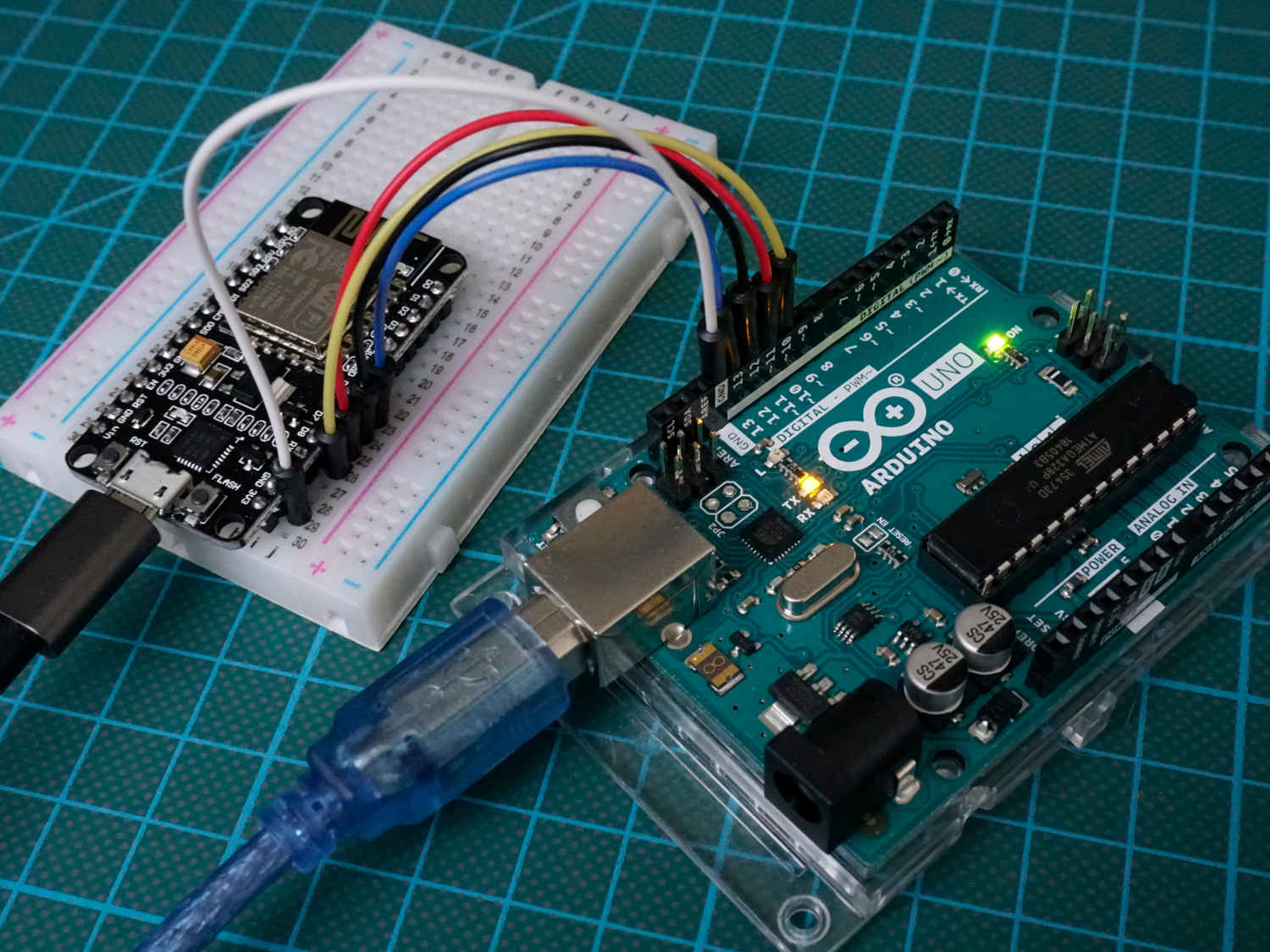
Table of Contents
Like I2C, SPI is a synchronous serial data protocol and therefore need a clock to synchronize the communication between master and slave devices.
SPI is recommended when the communication speed needs to bet very fast. The maximal throughput is up to 10,000,000 bits/s and much faster than I2C and UART. The speed which can be used by the microcontroller is based on the chip rate (clock rate). Most Arduino microcontroller have a chip rate of 16 MHz but it is recommend to set the communication speed to ½ of the chip rate 8 MHz (8,000,000 bits/s). The ESP8266 has a higher chip rate compared to the Arduino microcontroller with 80 MHz and it is recommended to reduce the communication speed for the ESP8266 microcontroller too.
To set the SPI clock relative to the system clock you use the function setClockDivider(). For example if you want to have a SPI throughput of 8 Mbits/s and your chip rate is 16 MHz you use the following function with the parameter setClockDivider(SPI_CLOCK_DIV2). The following dividers are available: 2, 4, 8, 16, 32, 64 or 128.
But in practice it is up to you if you want to select the communication speed manually via the function, because the Arduino selects the communication speed automatically equal or less than the setting based on the device with the lowest communication speed.
In a SPI system you always have only 1 master device. Therefore SPI is not able to build a multi-master system. If you want to communicate between for example an Arduino Uno and a NodeMCU, one device has to be the master and the other one the slave. But SPI is able to handle multiple slave devices, each one connected to the master device via the so called Slave Select (SS) line. Because the Slave Select line connects each slave with the master there is no unique address for each slave like for the I2C communication.
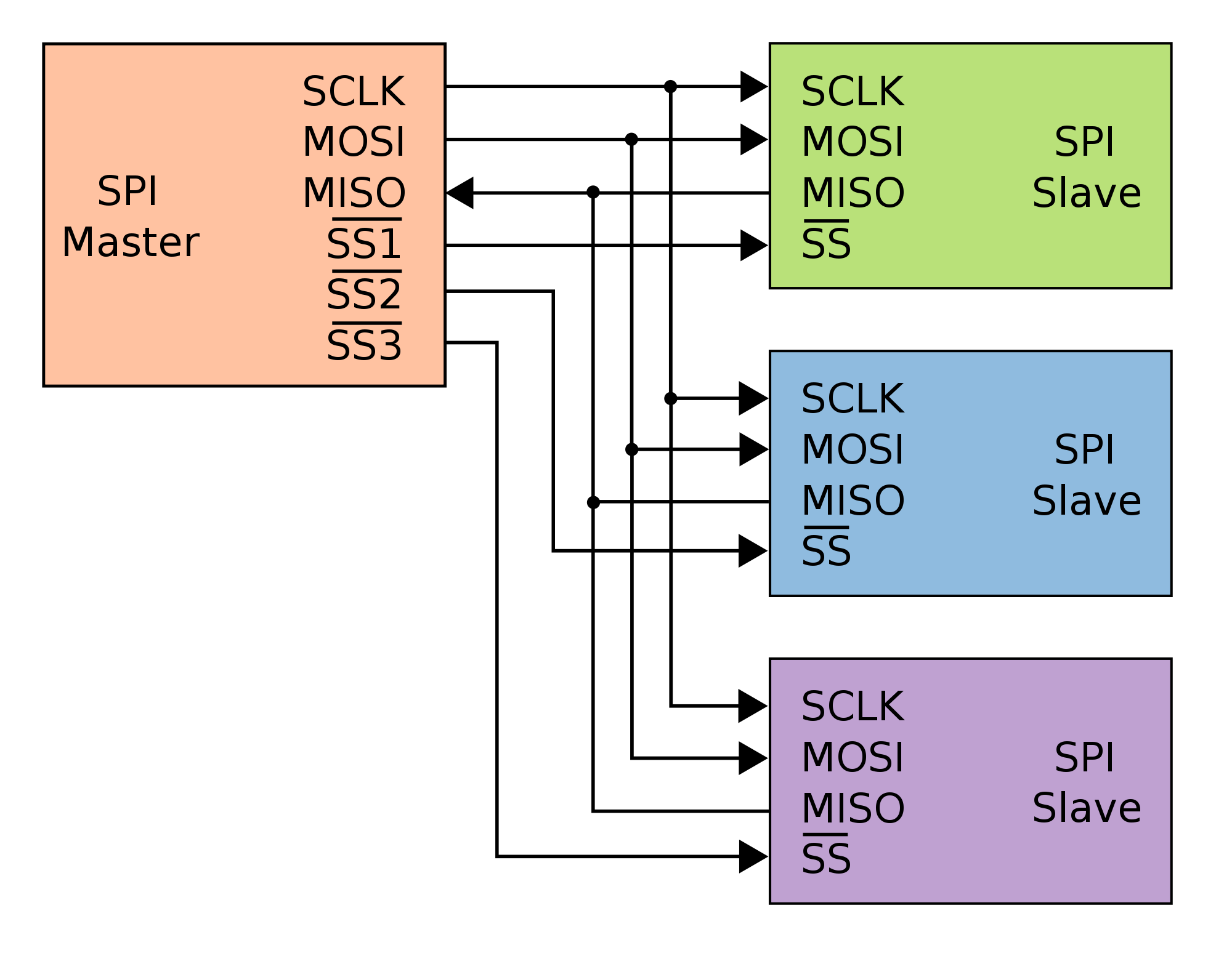
There are 3 lines which connect the master device to all slave devices
- MISO (Master in Slave Out): The Slave line for sending data to the master
- MOSI (Master Out Slave In): The Master line for sending data to the peripherals
- SCK/SCLK (Serial Clock): The pulse from the master device to synchronize data transmission
And 1 line from the master to each device
- SS (Slave Select) One specific line to each peripheral that the master can enable or disable the specific slave. This allows to share the MISO, MOSI and SCK line between multiple devices. The SS pin can be any digital pin on your microcontroller
- SS Pin is LOW → Slave communication to master is enabled
- SS Pin is HIGH → Slave communication to master is disabled
If you want to know what are the MISO, MOSI and SCK pins for different microcontrollers, you find this information in the related pinout articles: Arduino Mega, Arduino Uno, Arduino Nano, ESP8266 NodeMCU or better if you download the Microcontroller Datasheet eBook.
SPI Settings
If we want to start a communication, we first have to enable SPI with the following Arduino code SPI.beginTransaction(SPISettings(8000000, MSBFIRST, SPI_MODE0));
You see that when staring a SPI communication there are in total 3 settings which can be set if we want to control the settings manually. These SPI setting are not deleted when SPI communication is disabled with SPI.endTransaction(). Instead you can change the SPI settings by overwrite the settings via the function SPISettings(). There is always the option to let the microcontroller set the SPI settings automatically which we see in the examples in this tutorial.
Clock Rate
The first setting is the SPI clock rate which is set to 8 Mbits/s in this example.
Data Shifting
The second setting is the data shifting which defines which bit is transferred first. There are 2 options:
- Most Significant Bit (MSB) → MSBFIRST: Bit 8 is the first bit which is transferred via SPI
- Last Significant Bit (LSB) → LSBFIRST: Bit 1 is the first bit which is transferred via SPI
Most SPI chips use MSB first data order.
Modes of Transmission
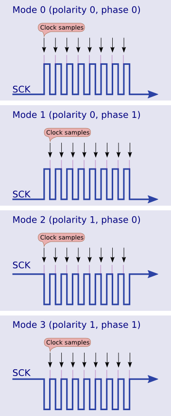
There are in total 4 different modes of transmission depending on the combination of 2 transmission settings:
- Clock Phase (CPHA)
- CPHA=1: Samples of the rising edge of clock pulse
- CPHA=0: Samples of the falling edge of clock pulse
- Clock Polarity (CPOL)
- Clock idle when high (CPOL=1): Each cycle consists of a pulse of 0. The leading edge is a falling edge and the tailing edge is a rising edge.
- Clock idle when low (CPOL=0): Each cycle consists of a pulse of 1. The leading edge is a rising edge and the tailing edge is a falling edge.
The following table shows the 4 different modes of transmission.
For most devices SPI_MODE0 is the default mode of transmission. The following pictures show the four different modes. You see the SCK line and when the clock samples.
SPI Data Transmission
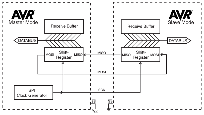
The data which is transferred via SPI communication is stored in 8-bit or 16-bit shift registers which have the same length for the master and slave device. Data is usually shifted out with the most significant bit first, defined by the SPI settings and stored as the new last significant bit of the shift register. The SPI module is unbuffered in the transmit direction and single buffered in the received direction. The following 6 steps describe the SPI data transmission:
- First the master device configures the SPI settings (clock rate, data shifting, mode of transmission).
- The master selects the slave device by pulling the SS line LOW (from logical 1 to logical 0).
- The following steps are done all at the same time during one clock cycle on a full-duplex data transmission:
- On the clock edge, the master sends the first bit to the slave via the MOSI line. The slave reads the incoming message.
- On the clock edge, the slave sends the first bit to the master via the MISO line. The master reads the incoming message.
- The data exchange is done, when the complete shift register is transmitted.
- The whole shift register is then copied into the receive buffer and the shift registers are reloaded. The data transmission processes starts again.
- If the transmission is complete, the master stops the clock signal and stops pulling the SS line LOW.
SPI Advantages and Disadvantages
Advantages
- Full duplex communication (I2C is not synchronous communication)
- Higher throughput than I2C
- Not limited to 8-bit words
- Lower power consumption than I2C because no pull up resistors are required
- Slaves do not need a unique address compared to I2C
Disadvantages
- Requires more pins than I2C
- No error checking protocol
- Many different variants because no formal standard defined
Examples of SPI Communication
The following table gives you an overview of all components and parts that I used for this tutorial. I get commissions for purchases made through links in this table.
I also give you two examples for the SPI communication because it is good to know the theory and how something is working. But in the end you want to realize projects and need examples to see how the SPI communication is done. The first one is a communication between the Arduino Uno as master and an Arduino Mega as slave. In the second example we build up a SPI communication between an ESP8266 NodeMCU as master and an Arduino Uno as slave.
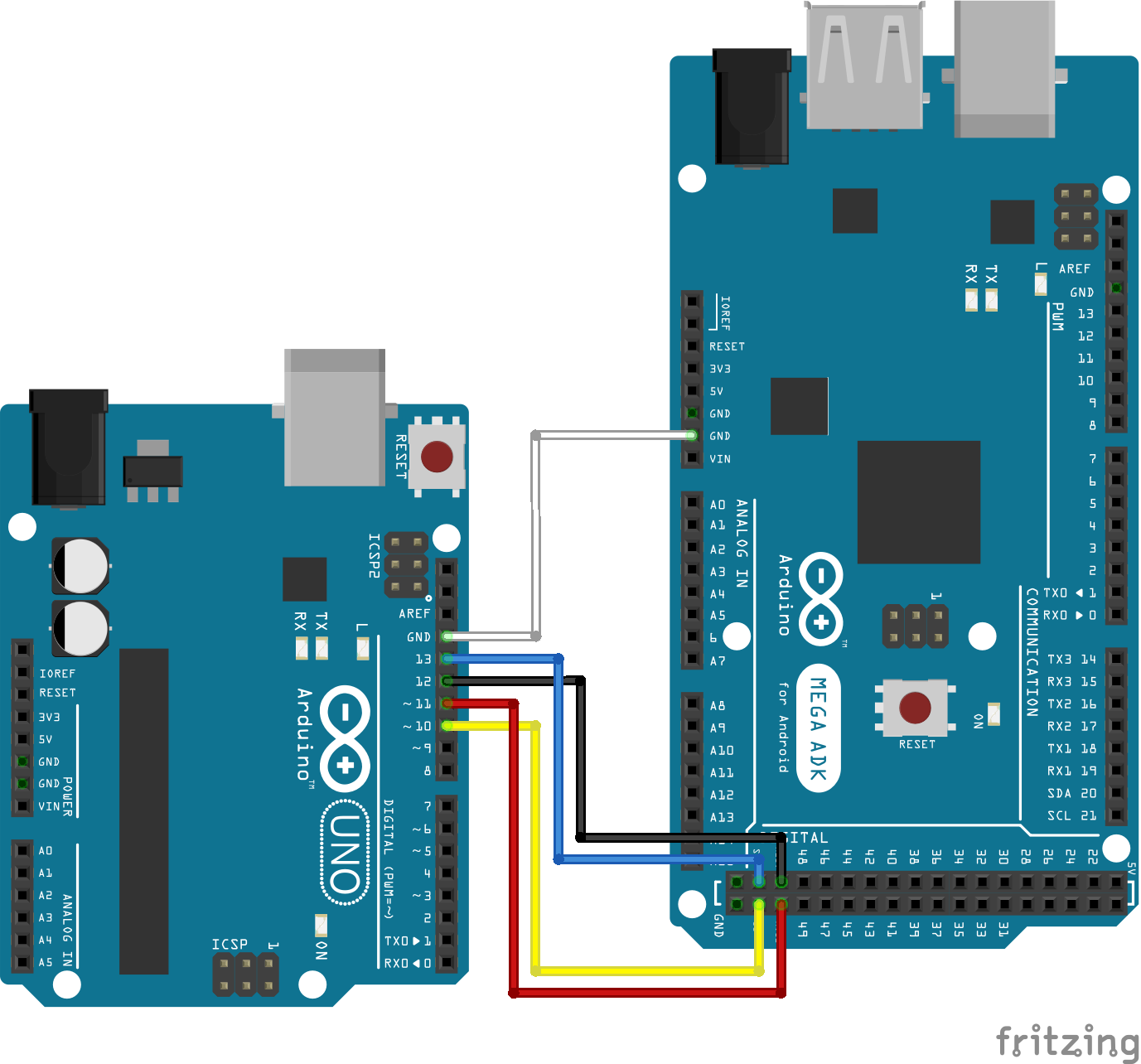
SPI communication: Arduino Uno to Arduino Mega
We want to communicate via SPI between an Arduino Uno as master and an Arduino Mega as slave. The following picture shows you the wiring. You also find the used pins in the pinout overview table in the special articles for the Arduino Uno and Arduino Mega.
In the following part we go step by step through the program script. At the end of this section you find a download button to download the whole script in one part for the master and slave.
Script for the master device: Arduino Uno
#include "SPI.h"

void setup() {
   digitalWrite(SS, HIGH); // disable Slave Select
   SPI.begin();
   SPI.setClockDivider(SPI_CLOCK_DIV4);//divide the clock by 4
}

void loop() {
   char c;
   digitalWrite(SS, LOW); // enable Slave Select
   for (const char * p = "Hello Mega\r" ; c = *p; p++)
   {
      SPI.transfer(c);
   }
   digitalWrite(SS, HIGH); // disable Slave Select
   delay(2000);
}
First we have to include the SPI library for our example. In the setup function we first disable the slave select pin by pulling the SS line HIGH. Then we initialize the SPI communication with the SPI.begin function. The last part of the setup function is optional. We divide the clock by 4 to reduce the SPI throughput from 16 MHz to 16/4=4 MHz.
The loop function starts with defining a character variable c and enable the slave select line by pulling the line LOW. We want to send the string “Hello Mega\r” and use the \r as flag to signal the slave device that the character transfer is done. Therefore the string is split into its letters in the for loop and transferred via SPI. When the transmission is complete the slave select pin is disabled and we wait for 2 seconds until we send the message from the master to the slave again.
Now you can upload the script for the Arduino Uno as master to the microcontroller. As mentioned before you find the complete script as zip file as download below.
Script for the slave device: Arduino Mega
#include "SPI.h"
char buff [50];
volatile byte indx;
volatile boolean process;

void setup (void) {
   Serial.begin (9600);
   pinMode(MISO, OUTPUT); // have to send on master in so it set as output
   SPCR |= _BV(SPE); // turn on SPI in slave mode
   indx = 0; // buffer empty
   process = false;
   SPI.attachInterrupt(); // turn on interrupt
}

ISR (SPI_STC_vect) // SPI interrupt routine
{
   byte c = SPDR; // read byte from SPI Data Register
   if (indx < sizeof buff) {
      buff [indx++] = c; // save data in the next index in the array buff
      if (c == '\r') //check for the end of the word
      process = true;
   }
}

void loop (void) {
   if (process) {
      process = false; //reset the process
      Serial.println (buff); //print the array on serial monitor
      indx= 0; //reset button to zero
   }
}
The slave script starts also with the inclusion of the SPI library. Also we have to define 3 variables. The buff variables stores the incoming values via SPI. The indx variable stores the index of the 8 bit and the process variable saves the current status of the transmission.
In the setup function, the baud rate is set to 9600 to view the SPI output in the serial monitor. The MISO pin is set as output to receive the data from the master. The SPI is set in slave mode and the two variables are set with their default values. Also interrupts are enables for the SPI communication.
After the setup function the SPI interrupt routine is defined. First the SPI data is read form the internal data register and stored in binary form. As long as the buffer is not completely filled with 50 characters, bit by bit is stored into the buffer from the SPI data register until the flag “\r” for the end of the character is found. If the message is completely transmitted, the variable process is set to TRUE.
The loop function waits until the process variable is TRUE and then first resets the variable and print the complete buffer on the serial monitor. The last part is to reset the index of the buffer to refill the buffer from the beginning.
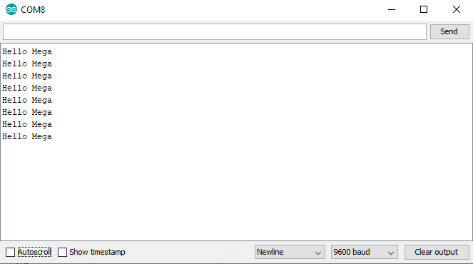
The following picture shows the serial output from the Arduino Mega as slave. The word “Hello Mega” is transferred via SPI.
SPI communication: ESP8266 NodeMCU to Arduino Uno
This second example uses the ESP8266 as master because for the slave script we saw in the first example that the IRS (spi_stc_vect) function is used because the SPI.attachInterrupt(); statement turns on the interrupt. Unfortunately the ESP8266 SPI library does not have an attachInterrupt() method and therefore it is not easy to access the SPI data register for the NodeMCU. Therefore I do not use ESP8266 NodeMCU as slave device.
The following picture shows the connection between the ESP8266 NodeMCU and the Arduino Uno.
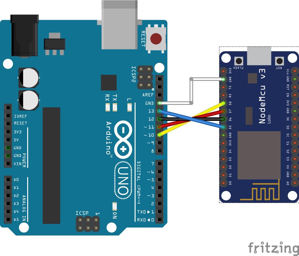
It is no problem to connect the Arduino and the NodeMCU directly even if the operating voltage for the Arduino is 5V and for the NodeMCU is 3.3V because the NodeMCU digital pins are 5V tolerant and protected from over-voltage.
The program code depends not on the specific micocontroller and therefore you can use the master and slave script from the previous example. But I want to show you a very short example for the master script from the ESP8266 microcontroller.
#include "SPI.h"
char buff[]="Hello Slave\n";

void setup() {
 SPI.begin();
}

void loop() {
 for(int i=0; i<sizeof buff; i++)
 {
  SPI.transfer(buff[i]);
 }
 delay(1000);
}
At the beginning we include the SPI library and the character array which holds the characters we want to transfer to the slave device. In the setup function we only initialize the SPI communication. In the loop function we transfer the character array letter by letter via SPI and then wait for 1 second. This is the shortest master script you can create which uses only the default settings for the SPI communication.
For the slave script we use the same as for the Arduino Mega.
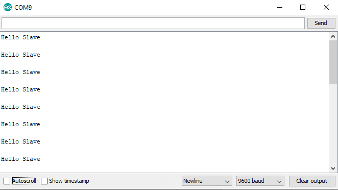
The following picture show the serial output for the SPI communication example between NodeMCU and Arduino Uno.
Use the following button to download the whole script for the master and slave device we discussed in this chapter. The Arduino files is packed as zip file.
View and Decode SPI Communication with an Oscilloscope
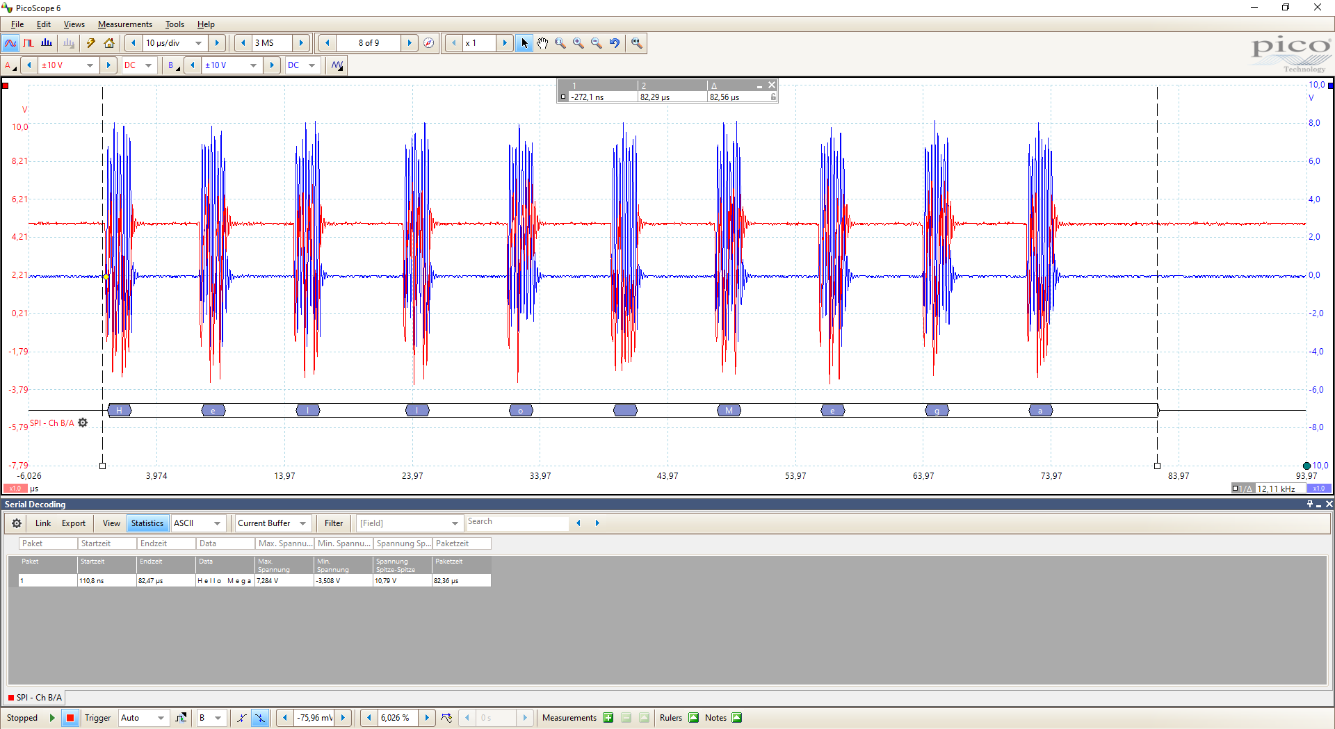
There is also the possibility that the SPI communication fails. If this happens it is very useful to know if the SPI communication on the MOSI line which is the output of the master is correct or not. Most oscilloscopes have the function to decode communication protocols like SPI. I have a 2 channel USB oscilloscope which is linked at the top of this article in the parts list.
I decoded the first example where we sent “Hello Mega” from the Arduino Uno to the Arduino Mega. I only connect the MISO and Clock signal each to one channel of my oscilloscope. In the following picture you see the decoded signal showing that the output from the Arduino Uno is correct, sending “Hello Mega”.
Click on the image to enlarge it.
Conclusion
In this tutorial we first compared the SPI communication protocol against I2C and UART. Also we discussed the SPI settings and how the data is transmitted between different devices. At the end of this article we looked at two examples and how SPI communication can be decoded and debugged with the help of an oscilloscope.
If you have any questions regarding the SPI communication, please use the comment section below to ask your questions. I will answer them as fast as possible.
hi, “hello slave” is not appear in nodemcu serial monitor. what should i do?
Hi can you send me your Arduino code to contact@diyi0t.com?
thank you @cdaviddav for the tutorial.
to myra: i think because there is no Serial.print() in NodeMcu code. if you want to monitor the output of serial, try add Serial.print code.
hi
thank you for Tutorial
I try run example
in slave mode an error appear in arduino IDE for esp32
error from this line 9:”SPCR |= _BV(SPE); // turn on SPI in slave mode”
===========
it is complete of error:
Arduino: 1.8.13 (Windows 7), Board: “ESP32 Dev Module, Disabled, Default 4MB with spiffs (1.2MB APP/1.5MB SPIFFS), 240MHz (WiFi/BT), QIO, 80MHz, 4MB (32Mb), 921600, None”
C:\Users\Mansour\Downloads\Compressed\Slave_Arduino_Mega\Slave_Arduino_Mega.ino: In function ‘void setup()’:
Slave_Arduino_Mega:9:4: error: ‘SPCR’ was not declared in this scope
SPCR |= _BV(SPE); // turn on SPI in slave mode
^
In file included from sketch\Slave_Arduino_Mega.ino.cpp:1:0:
Slave_Arduino_Mega:9:16: error: ‘SPE’ was not declared in this scope
SPCR |= _BV(SPE); // turn on SPI in slave mode
^
C:\Users\Mansour\AppData\Local\Arduino15\packages\esp32\hardware\esp32\1.0.4\cores\esp32/Arduino.h:99:25: note: in definition of macro ‘_BV’
#define _BV(b) (1UL < Preferences.
Hi,
It’s normal because SPCR |= _BV(SPE) change a bit value in the SPCR register of the ATMega328P where this bit value change the mode of the SPI module in the chip. I dont know which register in the ESP32 change this mode but you need to find how to put ESP32 in SPI Slave Mode. I recommand to use PlatformIO insted of AduinoIDE if you want to work with register and Peripheral Interface.
I have connected ESP32 DEVKIT Breakout board VSPI pins (D4,D5,D18,D23,D19) to nRF24L01 Radio TxRx pins.
And I am using Arduino IDE.
I am looking for the code example for using ESP32’s SPI bus.
Please help.
ESP8266 is 5V tolerant, but as far as I know ESP32 is NOT.
I am looking into connecting ADE7758 to ESP32 via SPI and I am faced with this problem.
Any idea other then bi-directional logic level converter ?