Building a Menu with Buttons for your Microcontroller
In this tutorial we build a menu with in total 4 buttons and 1 LCD screen for your microcontroller to control a running program.
The article is divided into two parts:
- Wiring of the microcontroller, buttons and LCD display to create a menu.
- Create the program script to control predefined variables like a temperature.
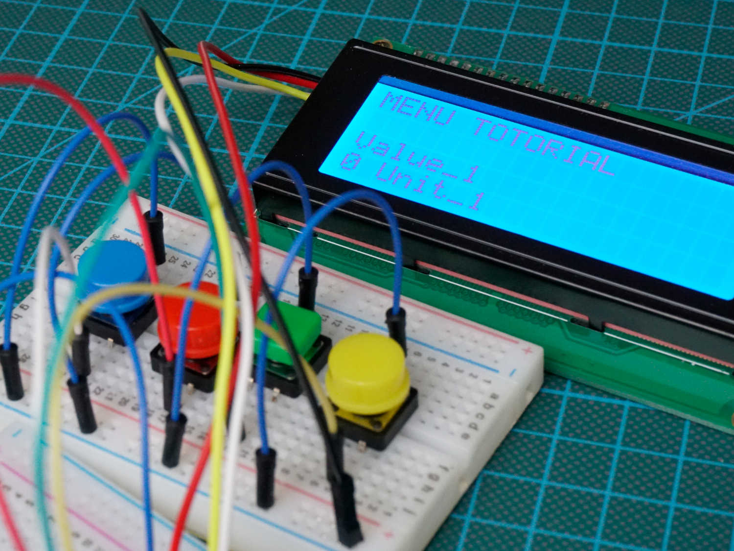
Table of Contents
I came up with the idea for a menu when I planned a new project for a temperature controller for my smoker. I thought that it would be cool not only to display the current temperature of multiple temperature probes on the LCD screen but also to give me an overview what is the selected target temperature of the meat. This is important because different kinds of meat have different target temperatures.
You can transfer my example also in the smart home area. For example you can also have a menu to display the temperature and humidity for different rooms in your house, each screen on the display showing the stats for one room. And if the humidity exceeds a predefined threshold, which can be set with the menu, you get an alarm on your phone.
In this tutorial we use a menu with 4 buttons:
The following picture shows the buttons on a breadboard for this tutorial. In a real project I would solder the buttons on a circuit board in a plus shape.
Button Menu Wiring
The following table gives you an overview of all components and parts that I used for this tutorial. I get commissions for purchases made through links in this table.
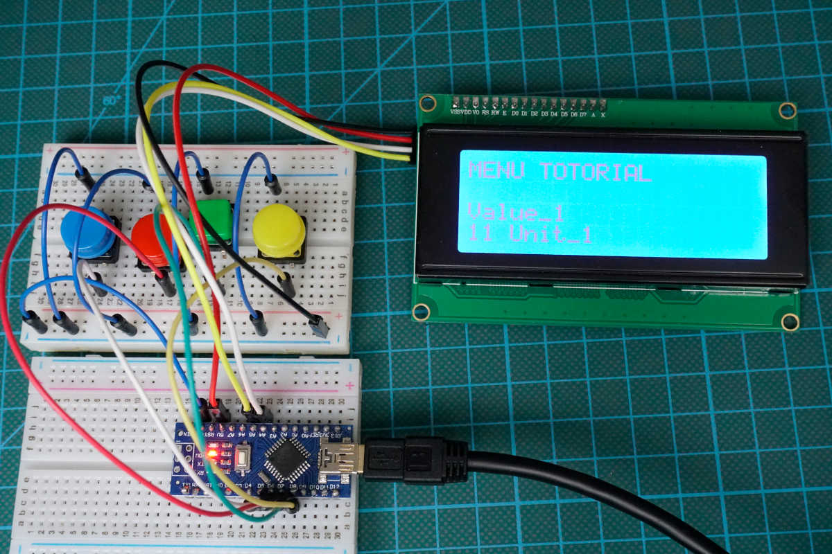
For this project I use an Arduino Nano. But you can use whatever microcontroller you want. The following fritzing sketch shows the connection between the Arduino Nano, the 4 buttons and the LCD screen.
I use a 20×4 LCD display with L2C communication. If you are also interested in LCD displays in general, I recommend you to look at my LCD display tutorial.
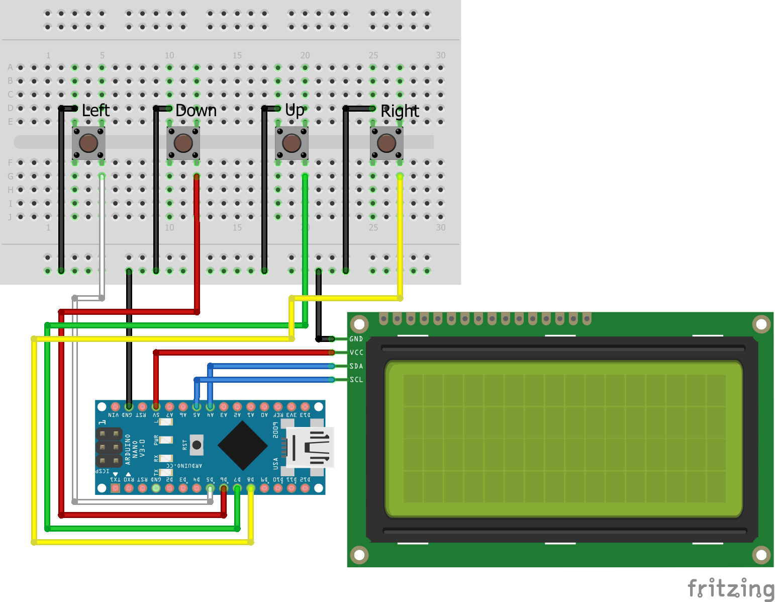
I do not use resistors for the connection to the buttons. Instead I use the internal pull up resistor of the Arduino Nano. The function of the internal pull up is the following: If the button is not pressed, the internal pull-up resistor is connected to 5V. Therefore the Arduino reports HIGH. However if we press the button, the Arduino pin is pulled to ground and reports LOW. We have to remember this later in the programming part of this tutorial.
Button Menu Program Script
Now lets dive into the Arduino program. This script is a little bit more complicated because the difficult part is not the connection between display, buttons and microcontroller but in the script to create the logic of the menu. But do not panic, we go step by step through the script and I describe every little detail.
#include "LiquidCrystal_I2C.h"
LiquidCrystal_I2C lcd(0x27, 16, 4);

const int buttonPinLeft = 5;
const int buttonPinDown = 6;
const int buttonPinUp = 7;
const int buttonPinRight = 8;

int buttonStateLeft = 0;
int buttonStateDown = 0;
int buttonStateUp = 0;
int buttonStateRight = 0;


const int numOfScreens = 4;
int currentScreen = 0;
String screens[numOfScreens][2] = {{"Value_1","Unit_1"}, {"Value_2", "Unit_2"}, {"Value_3","Unit_3"}, {"Value_4","Unit_4"}};
int parameters[numOfScreens] = {0, 10, 50, 100};


void setup() {
  Serial.begin(9600);
  lcd.init();   // initializing the LCD
  lcd.backlight(); // Enable or Turn On the backlight

  pinMode(buttonPinLeft, INPUT_PULLUP);
  pinMode(buttonPinDown, INPUT_PULLUP);
  pinMode(buttonPinUp, INPUT_PULLUP);
  pinMode(buttonPinRight, INPUT_PULLUP);

  lcd.clear();
  lcd.setCursor(4,1);
  lcd.print("THIS IS THE");
  lcd.setCursor(3,2);
  lcd.print("MENU TUTORIAL");
  delay(5000);
  lcd.clear();
}

void loop() {
  buttonStateLeft = digitalRead(buttonPinLeft);
  buttonStateDown = digitalRead(buttonPinDown);
  buttonStateUp = digitalRead(buttonPinUp);
  buttonStateRight = digitalRead(buttonPinRight);

  if(buttonStateLeft == LOW){
    lcd.clear();
    if (currentScreen == 0) {
      currentScreen = numOfScreens-1;
    } else {
      currentScreen--;
    }
}

  else if (buttonStateDown == LOW){
    lcd.clear();
    parameters[currentScreen]--;
}

  else if (buttonStateUp == LOW){
    lcd.clear();
    parameters[currentScreen]++;
}

  else if (buttonStateRight == LOW){
    lcd.clear();
    if (currentScreen == numOfScreens-1) {
      currentScreen = 0;
    } else {
      currentScreen++;
    }
}

  printScreen();
  delay(200);
}


void printScreen() {
  if (currentScreen == 3) {
    lcd.setCursor(0,0);
    lcd.print(screens[0][0]);
    lcd.print(": ");
    lcd.print(parameters[0]);
    lcd.print(" ");
    lcd.print(screens[0][1]);

    lcd.setCursor(0,1);
    lcd.print(screens[1][0]);
    lcd.print(": ");
    lcd.print(parameters[1]);
    lcd.print(" ");
    lcd.print(screens[1][1]);

    lcd.setCursor(0,2);
    lcd.print(screens[2][0]);
    lcd.print(": ");
    lcd.print(parameters[2]);
    lcd.print(" ");
    lcd.print(screens[2][1]);

    lcd.setCursor(0,3);
    lcd.print(screens[3][0]);
    lcd.print(": ");
    lcd.print(parameters[3]);
    lcd.print(" ");
    lcd.print(screens[3][1]);
  }
  else {
    lcd.setCursor(0,0);
    lcd.print("MENU TOTORIAL");
    lcd.setCursor(0,2);
    lcd.print(screens[currentScreen][0]);
    lcd.setCursor(0,3);
    lcd.print(parameters[currentScreen]);
    lcd.print(" ");
    lcd.print(screens[currentScreen][1]);
  }
}
First we import the necessary library for the I2C LCD display communication and create and LiquidCrystal_I2C object. The object has in total three variables:
- I2C Hex address: 0x27
In my case the I2C LCD display for the menu is connected on Hex address 0x27. This is the default address for this display. Either you can try the script with the same address of you can find out the I2C Hex address with a I2C Hex address scanner. You find the script and description for the I2C Hex address scanner in this article. - Digits in a row: 20 and number of rows: 4
In my case I use a 20×4 LCD display. If you use a 16×2 display you have to modify the code because we are using more than 2 lines of the display.
If you are not sure how to install the LiquidCrystal_I2C library, you find a step by step tutorial in this article.
Now we define in total 4 different variables with the pin number to know on what signal the different buttons send their state to the Arduino. For example the down button is connected to pin 6.
The buttonState variables store the current state of the button. At the beginning of the script the buttons have the state 0. If a button is pressed it gets the state 1. With this state we know later in the script which button was pressed and can trigger the reaction.
After we care about the buttons, we come to the screens. The first variable defines the number of screens we want to show. In this case we want to create 4 screens. The second variable defines the screen which is shown at the start of the program. We define the screen 0. And here comes the first obstacle, because we now we create a two-dimensional array. In each of the 4 screens we want to save 2 variables. The 2 variables are a value and a unit and could be temperature and kelvin. The variable of the current screen is 0 because we access the first element of an array in Arduino with 0 and not 1.
The following table shows the two-dimensional array.
The last variable we declare is an array which stores the current value of the screen. Because we have in total 4 screens, we store 4 values which can be increased or decreased.
After all variables are defined we take care about the setup function which will only run once at the start of the microcontroller. First we define the baud rate to 9600 which means that we can see values in the serial monitor with a data rate of 9600 bits per second. The baud rate defined in the setup function and in the serial monitor has so be synchronous.
After setting the baud rate we initialize the LCD display and turn the backlight on.
Then we initialize the 4 buttons with their pins and we enable the internal pull-up resistor so that we do not need an additional resistor for our circuit.
For the setup function we want to write a short text to the displays. First we clear the complete display and set the cursor in the second line on digit number 4. Here we print the first part of the text. Then we place the cursor in the next line and because the second part of the test is longer we set the cursor to the 3 digit number and print the second part of the text. The text is shown 5 seconds and after that time the display is cleared.
Now we enter the whole loop function which is of course processed over and over. The first 4 lines of the loop function are to read the current state of the buttons. If a button is pressed, the variable buttonState is LOW and we react in the following with the reaction depending on what button was pressed and then run the printScreen function which will be explained in the following section of this menu tutorial.
First we discuss the buttonStateLeft and buttonStateRight statement. We enter the first if query if the button is pressed and clear the screen to display the new screen without the old information. For the left button we decrease the pointer to show the screen before but when the pointer is already on the first screen (currentScreen == 0) we want to display the last screen to get a never ending rotation which you know from your mobile phone. For the right button we want to display the next screen. That is why we increase the variable currentScreen. If we reach the last screen we show the first screen also to get the functionality of a never ending loop in screens.
Now we want to discuss what happen if we push the button up or down. We first clear the screen too and then either increase or decrease the value of the current screen. The corresponding array which we defined earlier stores the changes values. For each screen we can therefore change the value.
The printScreen function has a lot of rows but is pretty easy and straight forward. First we check if we are in the last screen number 3. If so we want to display every number and unit line per line. Therefore we set the cursor in the first line and print the number name, number and unit. We do this line by line by changing the cursor.
If we are not in the last screen we want to display the title “MENU TOTORIAL” in the first line and use the last two lines to display the number name, number and unit.
I know that such tutorials can be a little bit dry but in the following video you see the button menu in action. You see me flipping through all screens and changing the values. Every time a value is changes is is also be stored and not overwritten from the initial values.
In this tutorial I showed you how to create a basic menu with 4 buttons, an LCD display and an Arduino Nano. Of course this are the basics but starting from here you can build you own menu and even more complex solutions. If you have problems building your menu or general questions to this tutorial, feel free to use the comment section below to ask your questions. I answer them as soon as possible.
Hi, is it possible to change the value (adc calibration).
Hi, do you mean the Value_X? Yes you can change this value
Bonsoir :je ce pas comment créer un menu pour géré la consigne de température et stocke dans EEPROM et aussi pour régler la date