I2C Tutorial for Arduino, ESP8266 and ESP32
In this tutorial we dive deeper into the I2C communication protocol.
You learn which practical examples:
- which pins you need for Arduino and ESP8266 microcontroller to connect devices through I2C.
- the advantages and disadvantages of this communication protocol
- how to use a I2C multiplexer
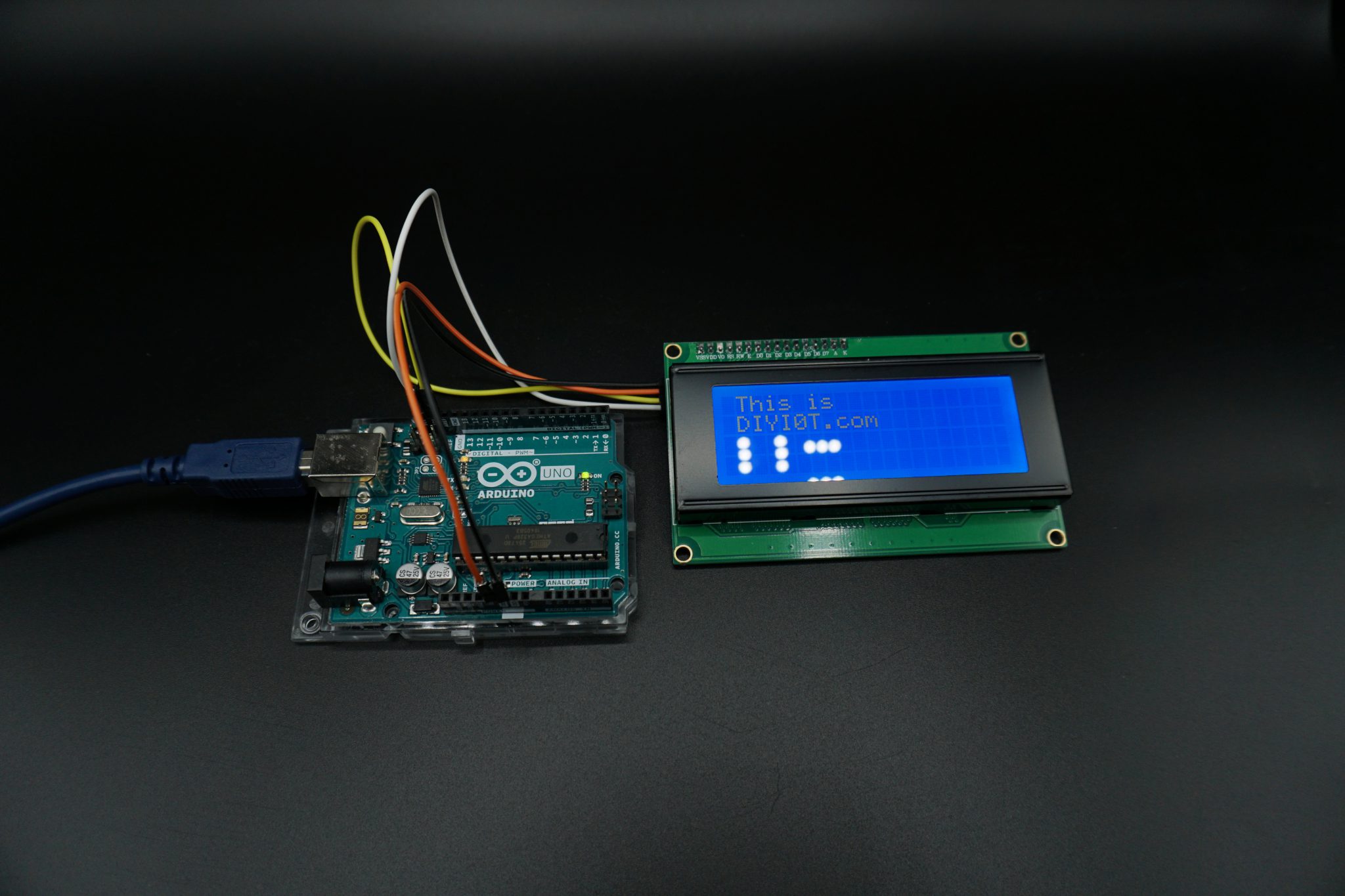
Table of Contents
The I2C communication is one out of three possible communication protocols, the Arduino / ESP8266 is able to communicate with other devices like OLED displays, barometric pressure sensors and so on. The two other communication protocols are SPI and UART.
I2C stands for Inter-Integrated Circuit was invented 1982 by Philips Semiconductor, now NXP Semiconductors.
I2C has multiple features which are also compared in the following table:
- Synchronous: The output of bits is synchronized to the sampling of bits by a clock signal shared between the master and the slave.
- Multi-master: You can have multiple masters controlling single, or multiple slaves.
- Multi-slave: You can connect multiple salves to a single master like SPI.
- Packet switched: The transferred data is grouped in packages / messages, made of a header and a payload.
- Single-ended: The data is transferred by a single wire.
- Serial connection: Data is transferred bit by bit along a single wire
| Description | I2C | SPI | UART | |
| Invented by | 1982 by Philips Semiconductor | 1970 by Motorola | 1960 by Gordon Bell at Digital Equipment Corporation | |
| Synchronous data transfer | A clock line is required to synchronize the communication | True | True | False |
| Asynchronous data transfer | Instead of a clock signal the data steam itself contain start and stop signals | False | False | True |
| Throughput | 10,000 to 1,000,000 bits/s | Up to 10,000,000 bits/s | Up to 115,200 bits/s | |
| Slave need unique address | True | False | False | |
| Number of pins required | 2 | 4+ | 2 | |
| Error checking protocol | True | False | True | |
| Multi-master | You can have multiple masters controlling one or multiple slaves | True | False | False |
| Multi-slave | You can connect multiple salves to a single master | True | True | False |
| Packet-switched | The transferred data is grouped in packages / messages, made of a header and a payload | True | False | False |
| Single-ended | The data is transferred by a single wire | True Serial Data (SDA) | False Master in Slave Out (MISO) Master Out Slave In (MOSI) | False |
| Serial connection | Data is transferred bit by bit along a single wire | True | True | True |
I2C reference design with timing diagram
On your Arduino / ESP8266 you will find two GPIOs (SDA and SCL) for the I2C communication. If you are not sure were to find the corresponding pins, see the following pictures or for the complete pinout you can vitis the following articles:
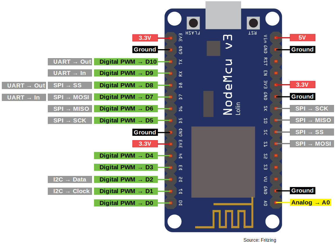
ESP8266 (NodeMCU)
SDA: D2 (I2C -> Data)
SCL: D1 (I2C -> Clock)
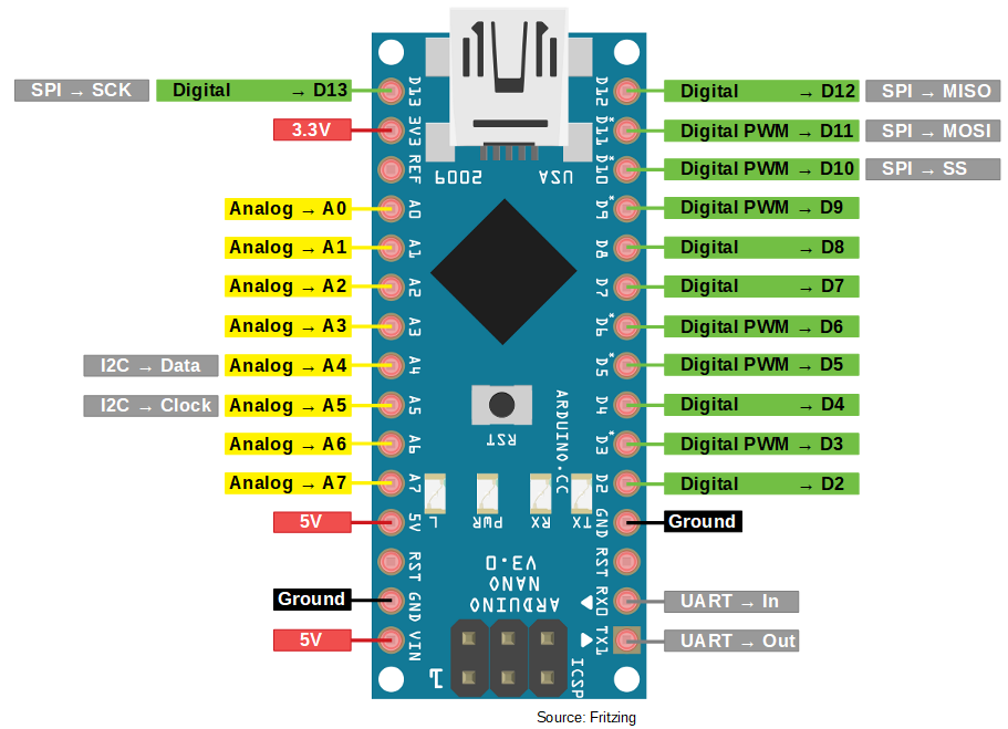
Arduino Nano
SDA: A4
SCL: A5
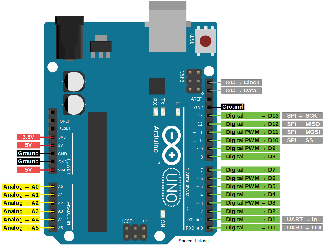
Arduino Uno
SDA: PIN18
SCL: PIN19
(no label on the PCB front, only visible from the side)
Arduino Mega
SDA: PIN20
SCL: PIN21
(no label on the PCB front, only visible from the side)

The two pins which you need for the I2C communication are the following:
- SDA (Serial Data): Connection between master and slave to send and receive data.
- SCL (Serial Clock): Shares the clock signal between the master and the slave, where the master always controls the clock signal.
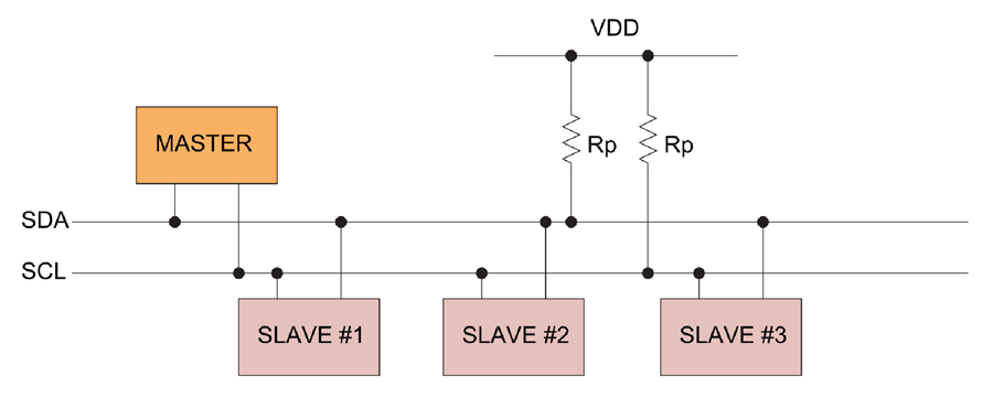
The Serial Data line and the Serial Clock line are pulled up with resistors. Therefore when there is no transmission of data on the bus, the SDA and SCL are in the HIGH state. Why a resistor is needed, see subsection “Physical layer”. Typical voltages are +5V and +3.3V and devices can communicate at 100 kHz or 400 kHz.
All I2C devices are connected to the bus either with open collector or open drain pins to pull the line LOW. The communication between master and slave occurs by toggling the lines by pulling LOW and releasing HIGH. Also bits are clocked on falling clock edges.
There may be four potential modes of operation for a given bus device, although most devices only use a single role and its two modes:
- master transmit – master node is sending data to a slave,
- master receive – master node is receiving data from a slave,
- slave transmit – slave node is sending data to the master,
- slave receive – slave node is receiving data from the master.
I2C Message Protocol
The I2C message protocol is divided bit by bit into fixed sections. In the following part of the article, we will take a closer look at the six different sections of the protocol.
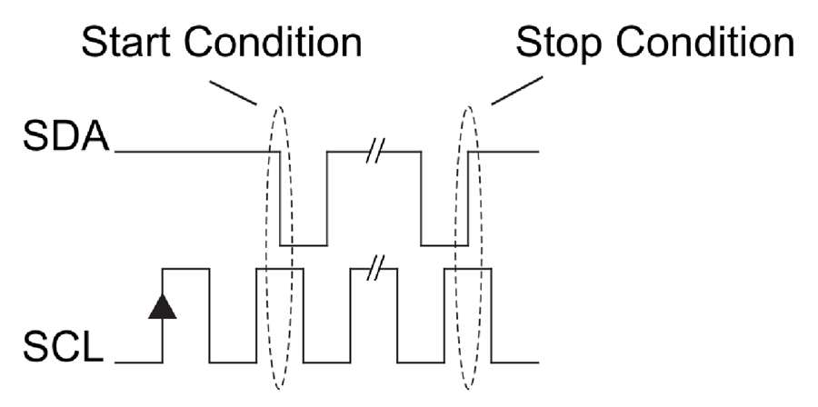
- Start condition: SDA: HIGH → LOW while SCL is HIGH
- Stop condition: SDA: LOW → HIGH while SCL is HIGH
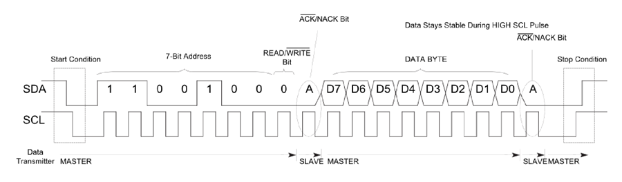
- Address Frame: The address frame is a 7 or 10 bit sequence to identify each slave for the master. The identifier is unique over all slaves. Each slave compares the address sent from the master to its own address. If the address matches, it sends a ACK bit → 0 back to the master. If the address doesn’t match, the slave does nothing and the SDA line remains high.
- Read/Write Bit
- Write: Master is sending data to the slave: 0
- Read: Master is requesting data from the slave: 1
- ACK/NACK Bit. If an address frame or data frame was successfully received, an ACK bit → 0 is returned to the sender from the receiving device.
- Data Frame: After the master detects the ACK bit from the slave, the first data frame is ready to be sent. The data frame is always 8 bits long and is followed by an ACK/NACK bit to verify that the frame has been received successfully. The master will continue generating clock pulses at a regular interval.
I2C Write Communication
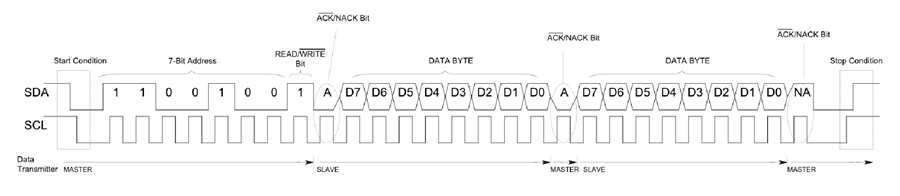
I2C Read Communication
Repeated Start Conditions
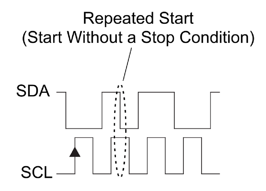
It is possible for the master to exchange several messages in one go, without allowing an other master device take control over the bus. Therefore a repeated start condition is defines as the following:
- SCL 0 → 0
- SDA 0 → 1
- SCL 0 → 1
- SDA 1 → 0
Note that there was not Stop condition.
Clock stretching
In some cases the masters data rate will be exceed the slaves ability to provide the requested data. Therefore the slave can hold down the SCL line after the master releases the SCL line. The master will wait for the click line to be released by the slave before proceeding to the next frame.
Physical Layer
Unlike UART or SPI connections, the I2C bus drivers are “open drain”, meaning that they can pull the corresponding signal line low, but cannot drive it high. Therefore, there can be no communication where one device is trying to drive the line high while another tries to pull it low. This architecture avoids errors in the communication.
But how is it possible to pull the signal line high? Each signal line has a pull-up resistor to restore the signal to high when no device is asserting the line to low.
A rule of thumb picking a resistor is 4.7 kΩ. The more devices are connected to the I2C communication the smaller has to be the resistor.
I2C allows for some flexibility in connecting devices with different I/O voltages. For an Arduino board with a voltage level of 5V as master, a slave of 3.3V will be work without problems. But if the voltage of the slave will be lower than 3.3V for example 2.5V there is the possibility to buy a I2C level shifter board.
I2C Speed Modes
- Low speed mode: 10 kbit/s
- Standard mode: 100 kbit/s
- Fast mode: 400 kbit/s
- Fast mode plus: 1 Mbit/s
- High speed mode: 3.4 Mbit/s
- Ultra fast mode: 5 Mbit/s
Advantages and Disadvantages of I2C communication
Advantages
- Only uses two wires
- Supports multiple masters and multiple slaves
- Well known and widely used protocol
Disadvantages
- Slower data transfer rate than SPI
- The size of the data frame is limited to 8 bits
I2C Examples
The following table gives you an overview of all components and parts that I used for this tutorial. I get commissions for purchases made through links in this table.
| Arduino Uno | Amazon | Banggood | AliExpress | |
| OR | ESP8266 NodeMCU | Amazon | Banggood | AliExpress |
| OR | ESP32 NodeMCU | Amazon | Banggood | AliExpress |
| AND | LCD Display 20×4 | Amazon | Banggood | AliExpress |
| OR | LCD Display 16×2 | Amazon | Banggood | AliExpress |
In the next section, we leave the theory behind us and attend to practical examples. Before we can control an I2C device, we first have to find out its HEX address. Therefore, our first example will be an I2C HEX address scanner. After we found out the HEX address of the I2C LCD display, we will control the display accordingly to send messages from the Arduino or NodeMCU via I2C to the LCD display.
The following pictures show the connection between Arduino Uno on the left side and NodeMCU on the right side with the I2C LCD display.

Arduino Uno
GND
5V
PIN18
PIN19
I2C LCD Display
GND
VCC
SDA
SLC
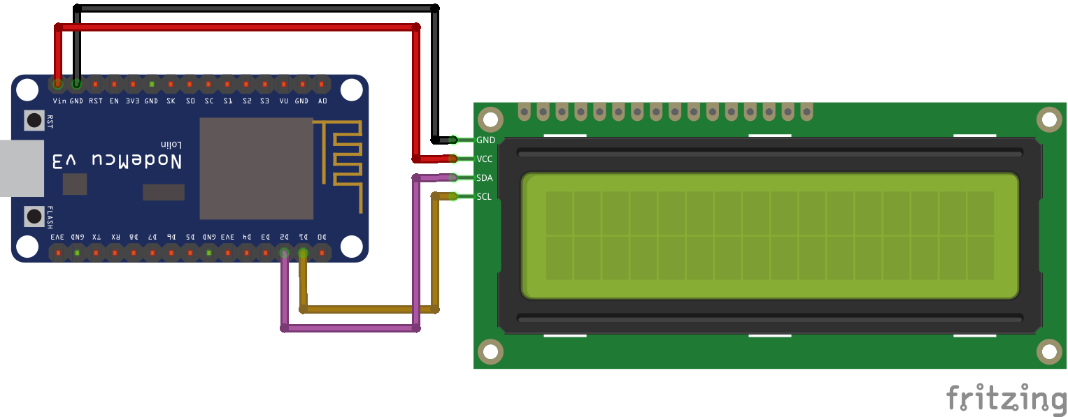
NodeMCU
GND
VIN
D2
D1
I2C LCD Display
GND
VCC
SDA
SLC
How to find the HEX Address?
#include "Wire.h"
The “Wire.h” library allows the microcontroller to communicate with I2C devices. Therefore this library is essential every time you want to use the I2C communication.
void setup(){
  Serial.begin(115200);
  while(!Serial){} // Waiting for serial connection

  Serial.println();
  Serial.println("Start I2C scanner ...");
  Serial.print("\r\n");
  byte count = 0;
This sketch uses only the setup function, because we want only one time to scan all connected devices. First we define the baud rate to 115200 and we will memorize to set the baud rate of the serial monitor to the same value. Than we wait until the serial connection is established that we are able to scan devices. After we define some cool printings on the serial monitor, we define a variable count to zero. The variable will be increased when we find an I2C device and is therefore the sum of connected I2C devices.
  Wire.begin();
  for (byte i = 8; i < 120; i++)
  {
    Wire.beginTransmission(i);
    if (Wire.endTransmission() == 0)
      {
      Serial.print("Found I2C Device: ");
      Serial.print(" (0x");
      Serial.print(i, HEX);
      Serial.println(")");
      count++;
      delay(1);
      }
  }
With Wire.begin() the microcontroller joins the I2C bus as master or slave. If no address is provided in the function like Wire.begin(address), the device joins as master like we want. To scan all possible I2C HEX addresses we use a for loop. To begin the transmission to the possible I2C slave we use the Wire.beginTransmission(address) function. If there is a valid I2C slave we get a 0 by ending the transmission to the slave through Wire.endTransmission(). We print the HEX address of the connected device on the serial monitor. Also if we found an I2C device we increase the counter by 1 and use a little delay before trying to connect to the next device.
  Serial.print("\r\n");
  Serial.println("Finish I2C scanner");
  Serial.print("Found ");
  Serial.print(count, HEX);
  Serial.println(" Device(s).");
}

void loop() {}
Feel free to copy the whole script in your Arduino IDE
#include "Wire.h"

void setup(){
  Serial.begin(115200);
  while(!Serial){} // Waiting for serial connection

  Serial.println();
  Serial.println("Start I2C scanner ...");
  Serial.print("\r\n");
  byte count = 0;

  Wire.begin();
  for (byte i = 8; i < 120; i++)
  {
    Wire.beginTransmission(i);
    if (Wire.endTransmission() == 0)
      {
      Serial.print("Found I2C Device: ");
      Serial.print(" (0x");
      Serial.print(i, HEX);
      Serial.println(")");
      count++;
      delay(1);
      }
  }
  Serial.print("\r\n");
  Serial.println("Finish I2C scanner");
  Serial.print("Found ");
  Serial.print(count, HEX);
  Serial.println(" Device(s).");
}

void loop() {}
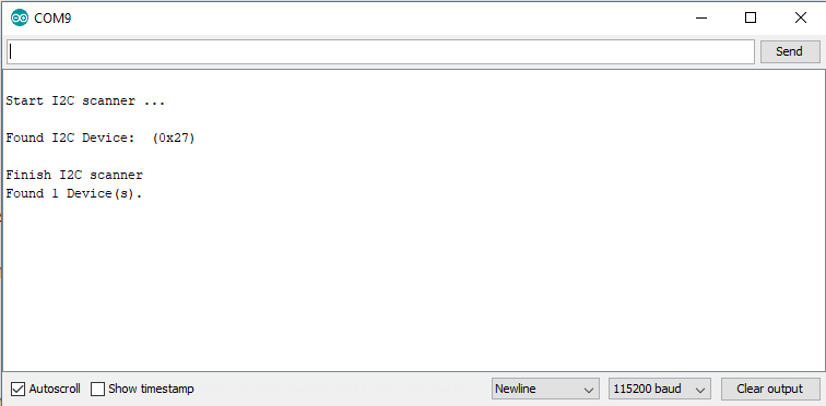
If we look at the serial monitor, the result is the following
Control an LCD Display
With the I2C HEX scanner we found out that the HEX address of the LCD display is 0x27. Now we can program the script to communicate with the LCD display. For this sketch we need the LiquidCrystal_I2C library. There is also a separate article about the LCD display with deeper technical informations.
First we have to include the Wire library we know from the I2C HEX scanner code and the new library LiquidCrystal_I2C which takes the huge work to provide us a easy to use interface for the LCD display.
We have to define the HEX address of our display and what display we are using like 16×2 or 20×4. I use the 20×4 display in this example.
In the setup function we use lcd.init() to initialize the connection between the microcontroller and the display. After the initialization we have to turn the backlight on with lcd.backlight().
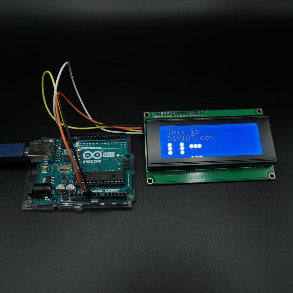
After the display is setup we can set the cursor to the position (column=1, row=0) and write our first part of the text. Then we set the cursor in the next row and write the rest of the string.
#include "Wire.h"
#include "LiquidCrystal_I2C.h"

// set the LCD address to 0x27 for a 16 chars and 2 line display
LiquidCrystal_I2C lcd(0x27, 20, 4);

void setup()
{
  lcd.init();

  lcd.backlight();
  lcd.setCursor(1, 0);
  lcd.print("This is");
  lcd.setCursor(1, 1);
  lcd.print("DIYI0T.com");
}

void loop(){}
I2C Multiplexer
If you want to connect a lot of sensors to your Arduino and your normal I2C connection comes to a limit? Maybe the sensors have the same I2C address. The solution to your problem is the PCF8574 1-to-8 I2C expander. The PCF8574 Breakout enables communication with multiple I2C devices that have the same address making it simple to interface with them. PCF8574 is an eight-channel I2C expander which allows eight separate I2C devices to be controlled by a single host I2C bus.
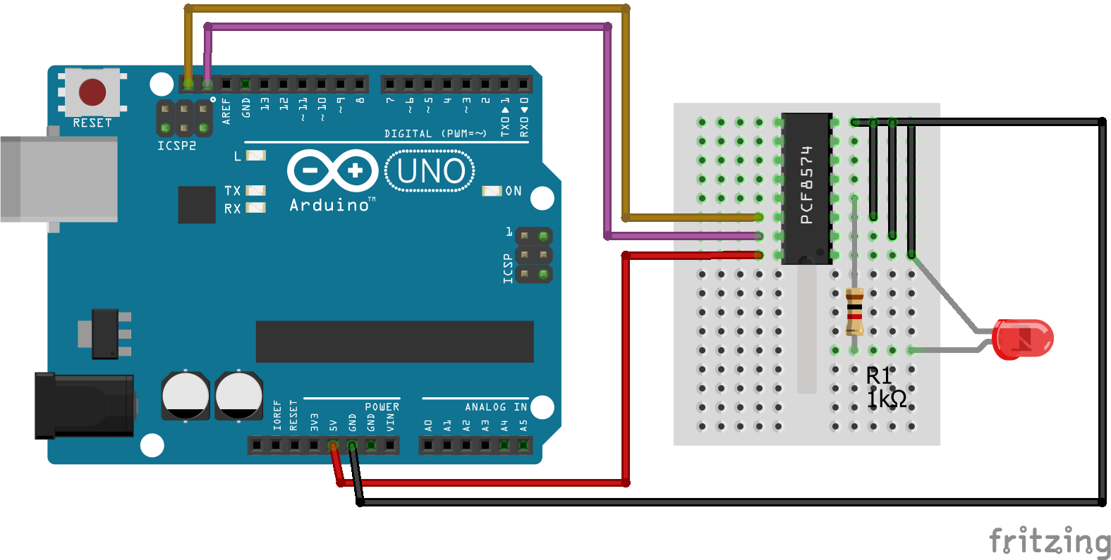
The PCF8574 is a 8-bit input/output (I/O) expander for the two-line bidirectional bus (I2C) and designed for operation voltages between 2.5V and 6V. The standby current consumption is very low with 10μA.
The PCF8574 is connected to the Arduino as follows:
VCC -> 5V
GND -> GND
SDA -> PIN18
SCL -> PIN19
P0…P7 are the P-port input/output with push-pull design structure. Here you connect your I2C devices to the PCF8574. We connected the LED on P0.
A0…A2 are address inputs for the PCF8574 itself. We do not need them and therefore connect them with GND.
Click here, if you want to look at the complete datasheet of the PCF8574.

The program code for the scanner and the control of the device is the same as above.
If you like to know how you can reduce the number of input pins for a keypad from 8 to only 2 I2C pins, with the help of the I2C multiplexer, then visit the keypad tutorial for Arduino, ESP32 and ESP8266.
Can you share an example where Arduino and Master and Node mcu is slave in I2C Communication with switches and LED as sensors anf actuator.
[…] – weryfikacja adresu i2c pracy czujnika (0x76 lub 0x77), z ciekawości można uruchomić skaner i2c i sprawdzić wszystkie podłączone czujniki (urządzenia) do magistrali i2c. Link 1 lub Link 2. […]
Many Thanks for this tutorial.
It was very helpful for understanding how I2C works and
how to connect different controller.
Especially ESP32 NodeMCU.
Hi Frank,
thanks for your comment. Nice that you like the tutorial. ESP32 NodeMCU -> my favorite microcontroller
Thank you! Your images of the expected start condition helped me understand what I saw on my scope and made me realised I’d forgotten to put the to address on the master sending the data!
Very interesting article.
In your comparison of the serial protocols, you note that for I2C, “Slave needs unique address’.
The ATMega I2C implementation includes an address mask register (TWAMR) which allows a slave device to have multiple addresses. You can then read the actual address from TWDR, when SLA+R or SLA+W has been received.
I am trying to find out if the ESP8266 also supports an I2C address mask and actual address recovery – but the ESP8266 documentation isn’t quite as good! Do you know the answer?
Thanks
Mk
Thanks for the great tutorial. I was struggling with getting my LCD to work until I ran the Wire code to scan and realized I was using the wrong address!
Hi Mohammed,
thank you for the comment. I also made this mistake at the beginning 🙂
Thanks for your extensive explanation.
I have a question: I would like to use a driver shield for motors in which the esp8266 fits. By default D1 and D2 (sda and scl) are already wired inside the shield to connect a motor, but I need to use I2C to connect 3 sensors. So I use “wire.begin (sda, scl)” but the ports I have are only GPI01, GPI03, GPI015, GPI09 and GPI010, but it doesn’t work with any combination of these ports. Remaining ports are used to initialize the sensors address I2C. Do you have any suggestions?
Thanks in advance