Keypad Tutorial for Arduino, ESP8266 and ESP32
In this tutorial you learn how to use the keypad with your Arduino, ESP8266 and also ESP32 microcontroller.
The Keypad is one of the most used input devices for Arduino applications.
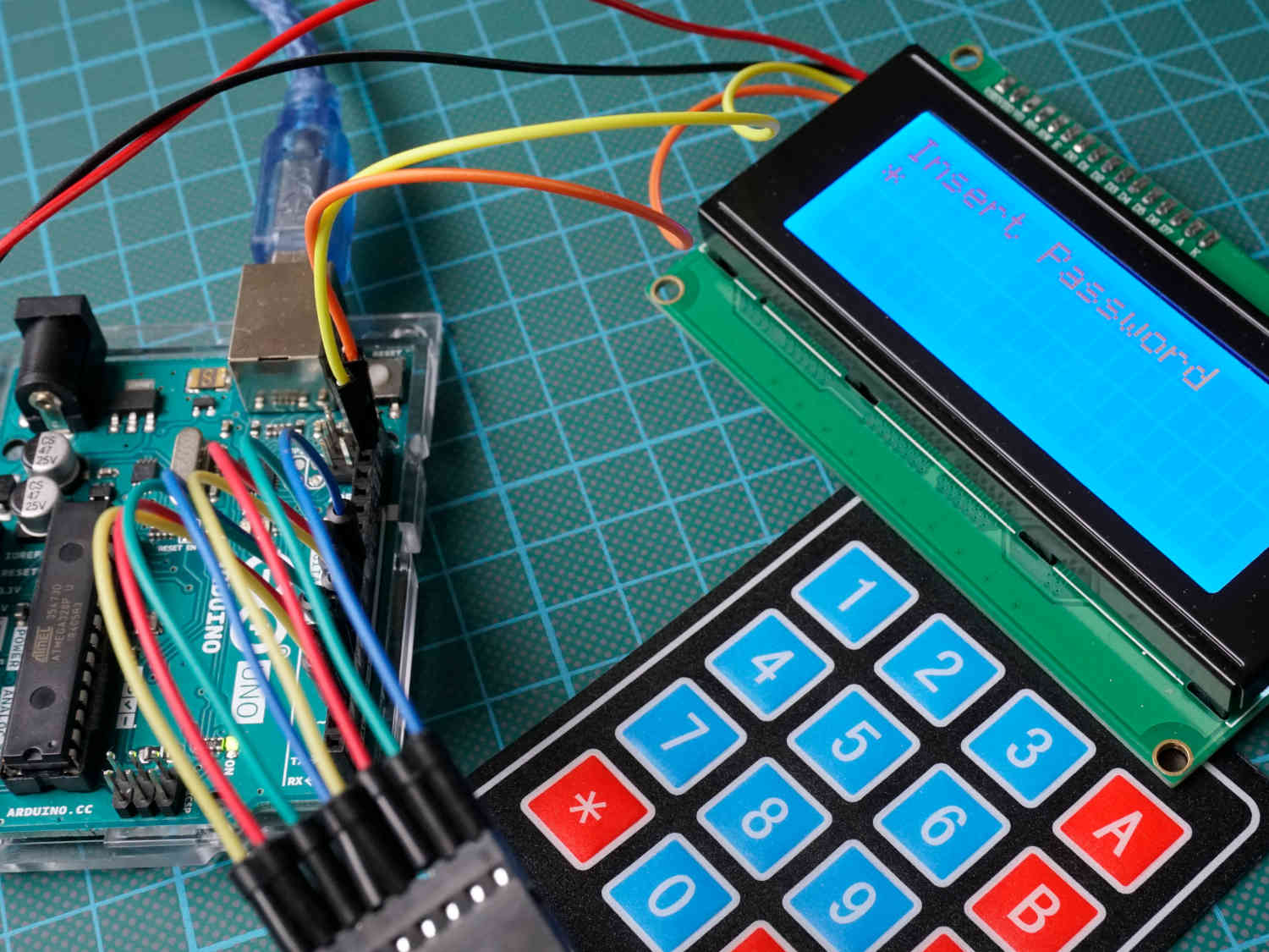
In this tutorial we build a lock which opens when we type in the correct password.
There are two different version of the keypad with the only difference in the number of buttons:
- The version with 3 columns and 4 rows which includes the numbers 0 to 9 with the asterisk (*) and hashtag (#) button
- I have the bigger version with 4 instead of 3 columns. The bigger version includes all buttons of the smaller version but has also buttons for the letters: A, B, C, D
Table of Contents
Functionality of the Keypad Matrix
The keypad is internally build like a matrix with rows and columns. The you can identify a cell in an Excel sheet with the row and column number, the Arduino is able to identify the pressed button on the keypad. The following picture shows that the first 4 connectors identify the row number (R1, R2, R3, R4) and the last 3 to 4 connectors identify the column number (C1, C2, C3, C4), depending on the version of the keypad.
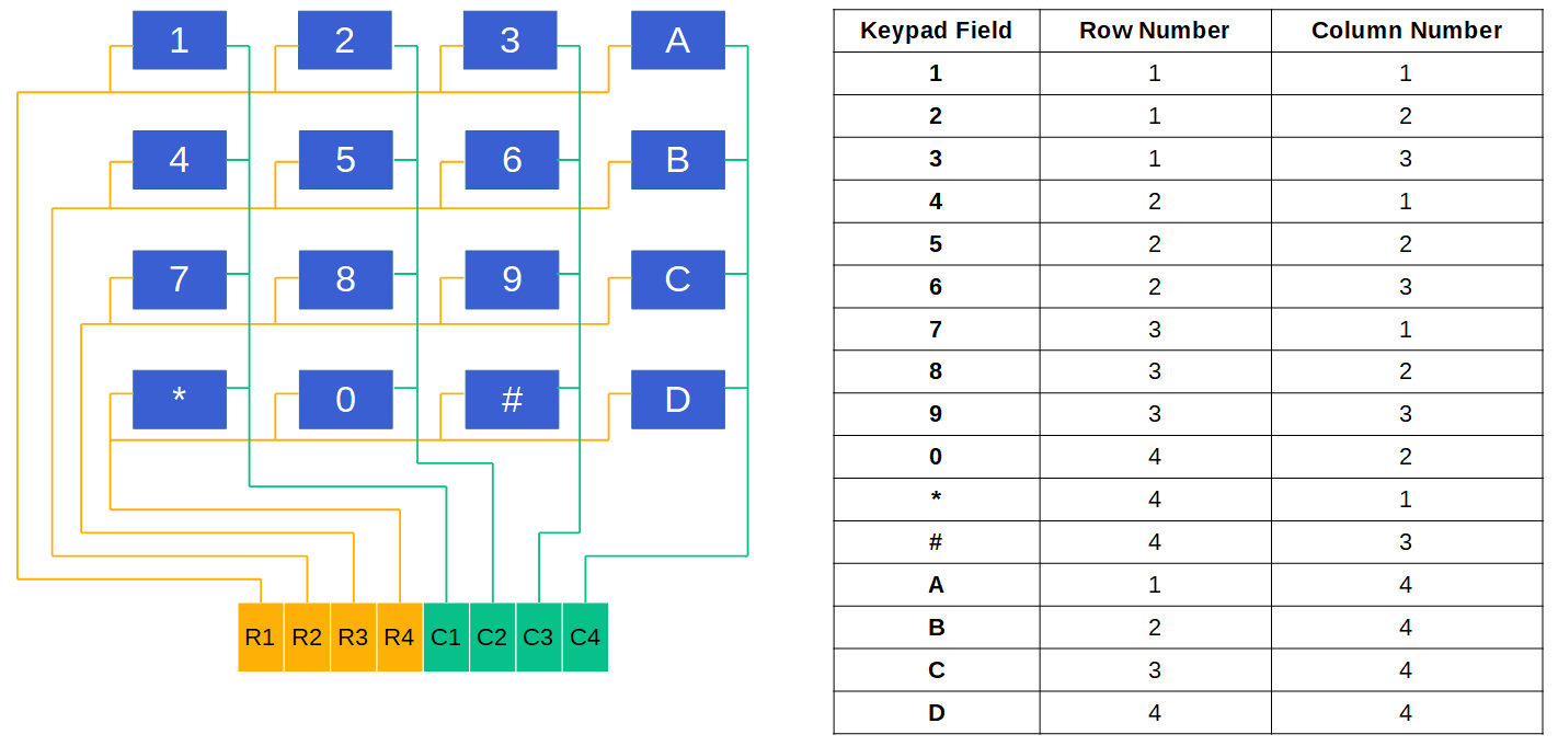
In the table on the right sight of the picture you see that if a button is pressed, the keypad field has a unique identifier, the row and column number. Therefore the microcontroller is able to identify the keypad field through a 4 step mechanism that is described with the following picture:
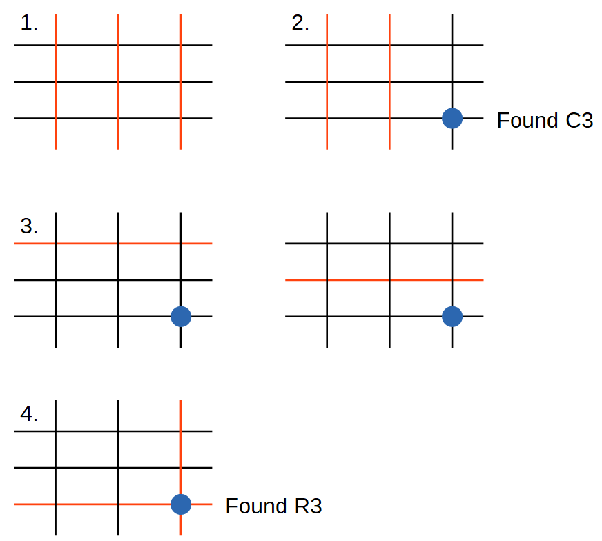
- In the idle state, every row pin is set to LOW and every column pin is set HIGH
- If one button is pressed, the column of this button is connected to LOW and therefore the column pin is pulled from HIGH to LOW. → The column is found.
- Now every row is pulled HIGH individually, stating by R1. All columns are LOW.
- If the row, where the button is pressed is pulled HIGH, the column changes from LOW to HIGH. → The row is found.
Wiring between Microcontroller and Keypad
Now, after we know how the keypad works, Is show you how to connect the keypad to your microcontroller. The following picture shows the wiring between the most used Arduino, ESP8266 and ESP32 microcontroller and the keypad. If you are missing your favorite microcontroller, leave a comment at the bottom of this article and I will also add you microcontroller.
If you are interested how you can reduce the number of used digital I/O pins, the last chapter of this tutorial shows you how to use an I2C multiplexer to reduce the number of digital I/O pins to two.

Keypad Arduino Nano
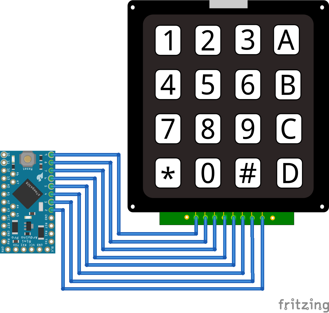
Keypad Arduino Pro Mini
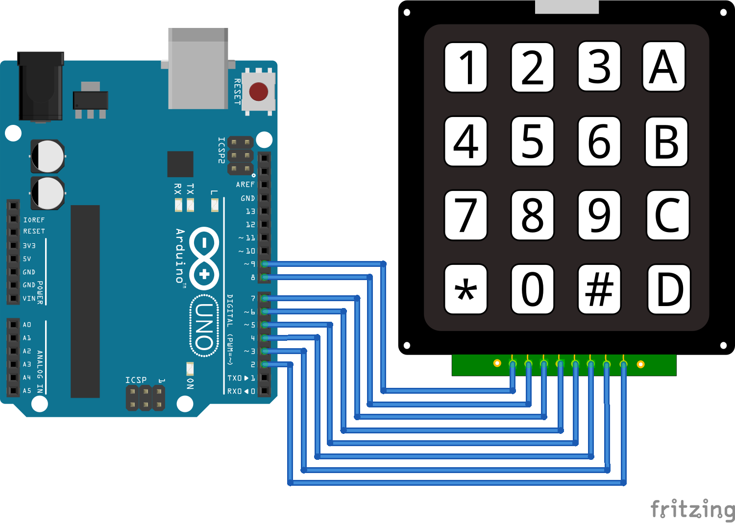
Keypad Arduino Uno
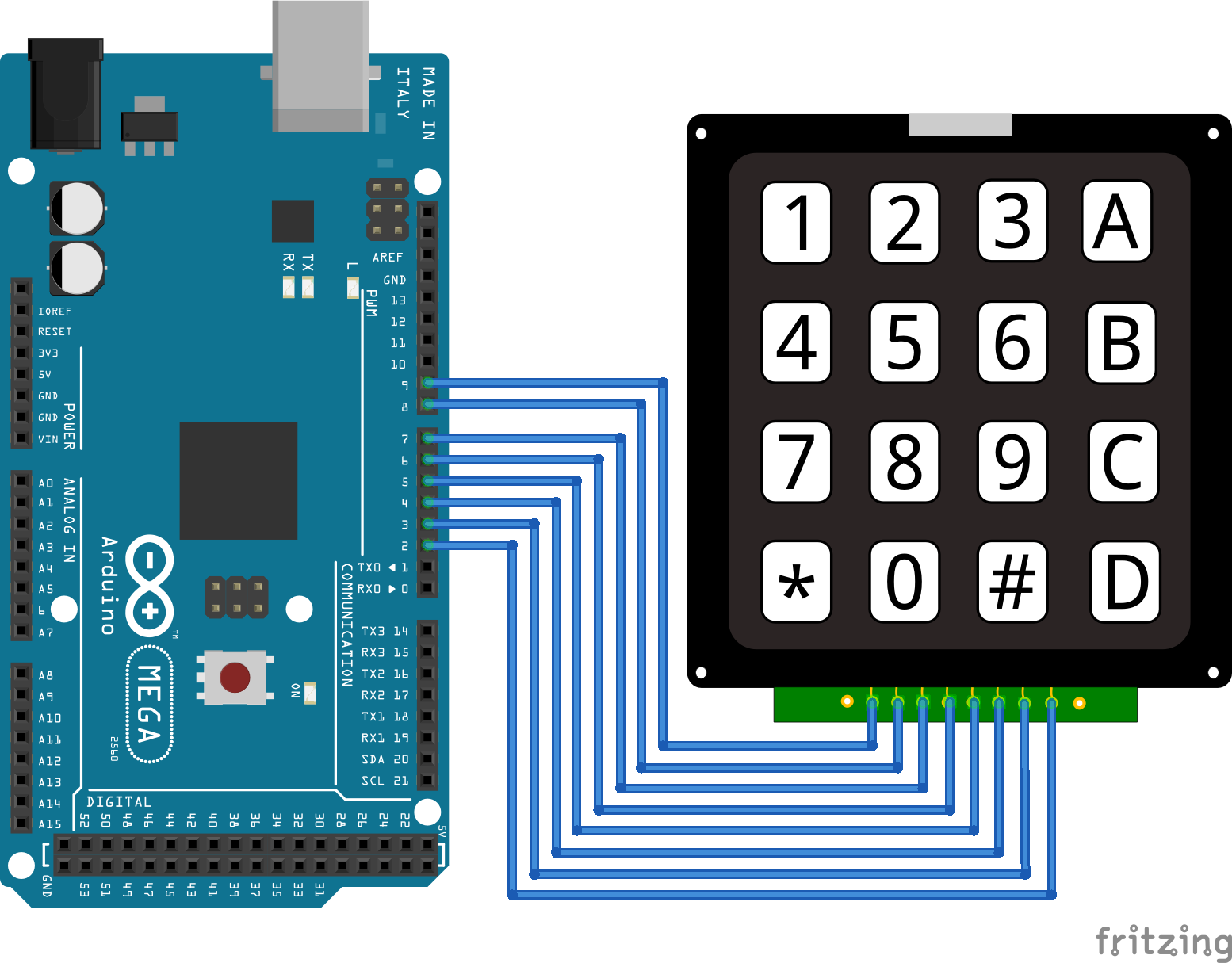
Keypad Arduino Mega
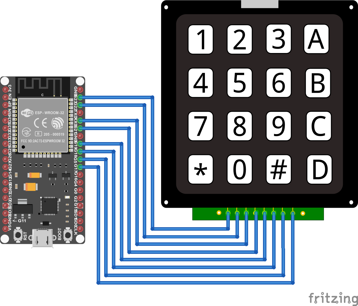
Keypad ESP32 NodeMCU
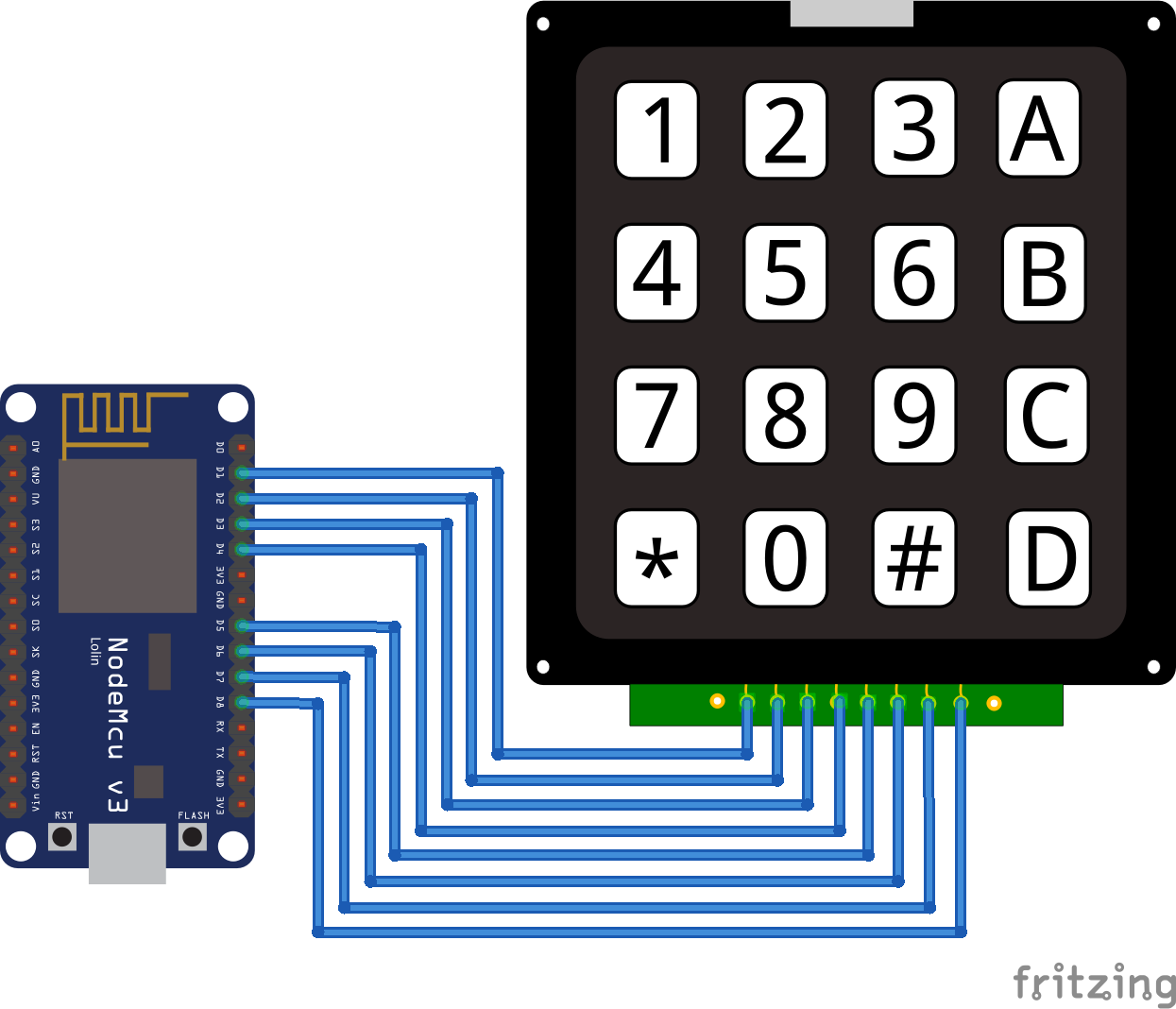
Keypad ESP8266
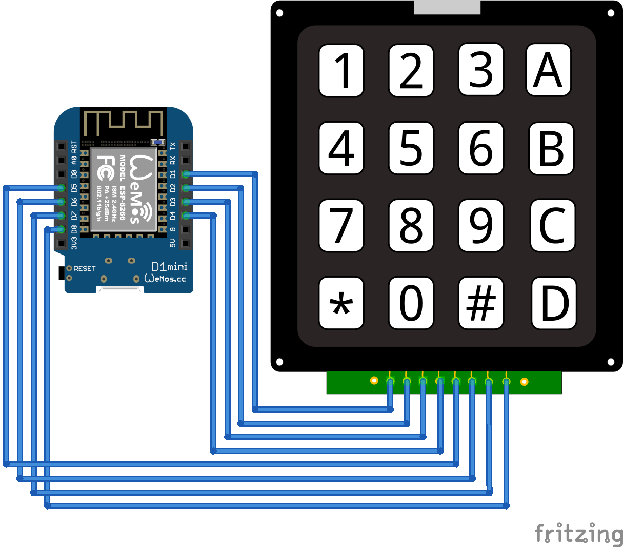
Keypad ESP8266 WeMos D1 Mini
Basic Keypad Example
Now, after we know how the keypad is wired to your microcontroller, we make a basic example. In this example we want to display the number which is pressed in the serial monitor. If this example is to easy for you, at the end of this article there is also a more advanced example where we build a password lock.
The following table gives you an overview of all components and parts that I used for this tutorial. I get commissions for purchases made through links in this table.
For this example we use the Keypad library of Mark Stanley and Alexander Brevig which make the use of the keypad very easy. This library support the 3×4 and 4×4 keypad. If you do now know how to install a library, click here for a step by step tutorial.
After we wire everything up, let’s dive into the program code:
#include "Keypad.h"
const byte ROWS = 4; //four rows
const byte COLS = 4; //four columns

char keys[ROWS][COLS] = {
  {'1','2','3','A'},
  {'4','5','6','B'},
  {'7','8','9','C'},
  {'*','0','#','D'}
};

// For Arduino Microcontroller
byte rowPins[ROWS] = {9, 8, 7, 6};
byte colPins[COLS] = {5, 4, 3, 2};

// For ESP8266 Microcontroller
//byte rowPins[ROWS] = {D1, D2, D3, D4};
//byte colPins[COLS] = {D5, D6, D7, D8};

// For ESP32 Microcontroller
//byte rowPins[ROWS] = {23, 22, 3, 21};
//byte colPins[COLS] = {19, 18, 5, 17};

Keypad keypad = Keypad(makeKeymap(keys), rowPins, colPins, ROWS, COLS);

void setup() {
  Serial.begin(9600);
}

void loop() {
  char key = keypad.getKey();

  if (key){
    Serial.println(key);
  }
}
In the first line we include the previous or already installed library Keypad. Then we define the number of rows and columns your keypad has. In my case I have to 4×4 keypad.
To be able to identify the keypad right we create a matrix with the keypad. If your keypad has a different layout, then you can change the layout with this matrix. Make sure that the number of rows and columns is right.
The last part in the section where we define the variables for the wiring between the microcontroller and the keypad. You can use every digital I/O pin on your microcontroller. In my case I used the pins 2 to 9 for Arduino, pins D1 to D8 for all ESP8266 microcontroller and the first digital pins on one site of the ESP32 NodeMCU. The program code is commented for Arduino boards. If you want to use for example an ESP32 NodeMCU, you have to uncomment the lines of code for the ESP32 and comment the lines for the Arduino boards.
Next the library Keypad has to know what keypad is connected to the microcontroller. Therefore we create an object called keypad from the library and pass the previous defined variables to this object.
For the setup function we define the baud rate to 9600. Make sure that the baud rate of your serial monitor in the Arduino IDE is also set to 9600.
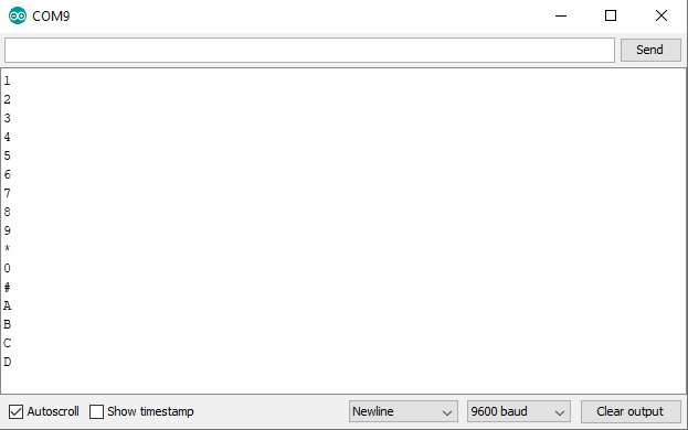
In the loop function we first read the character which we get from the keypad and store this character in the key variable. If the key variable is not empty, we print the character to the serial output.
The following picture shows the numbers in the serial monitor.
Keypad Password Lock Example
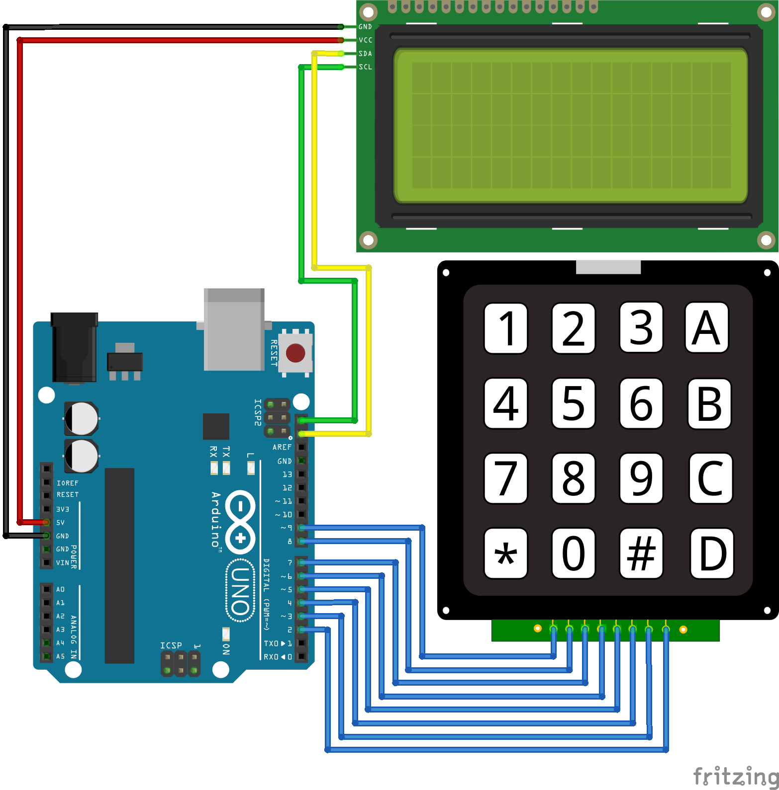
Now the more advanced example where we build a lock which opens when we type in the correct password. In this example I use the keypad and an LCD display along with an Arduino Uno. If you want to use an ESP8266 or ESP32 board, you can use the wiring from the previous chapter and only have to add the LCD display.
You see that we only connected the LCD display and that the magic happens inside the program code which I explain step by step in the following section. At the end of this section you can download the complete Arduino code as zip file.
#include "Keypad.h"
#include "Wire.h"
#include "LiquidCrystal_I2C.h"

const byte ROWS = 4; //four rows
const byte COLS = 4; //four columns

char keys[ROWS][COLS] = {
  {'1','2','3','A'},
  {'4','5','6','B'},
  {'7','8','9','C'},
  {'*','0','#','D'}
};

// For Arduino Microcontroller
byte rowPins[ROWS] = {9, 8, 7, 6};
byte colPins[COLS] = {5, 4, 3, 2};

// For ESP8266 Microcontroller
//byte rowPins[ROWS] = {D1, D2, D3, D4};
//byte colPins[COLS] = {D5, D6, D7, D8};

// For ESP32 Microcontroller
//byte rowPins[ROWS] = {23, 22, 3, 21};
//byte colPins[COLS] = {19, 18, 5, 17};

Keypad keypad = Keypad(makeKeymap(keys), rowPins, colPins, ROWS, COLS);
LiquidCrystal_I2C lcd(0x27, 20, 4);

const int len_key = 5;
char master_key[len_key] = {'1','2','3','4','1'};
char attempt_key[len_key];
int z=0;

void setup() {
  Serial.begin(9600);
  lcd.init();
  lcd.backlight();
  lcd.setCursor(0,0);
  lcd.print("Insert Password");
}

void loop() {
  char key = keypad.getKey();
  lcd.setCursor(z-1,1);
  lcd.print("*");
  if (key){
    switch(key){
      case '*':
        z=0;
        break;
      case '#':
        delay(100); // added debounce
        checkKEY();
        break;
      default:
         attempt_key[z]=key;
         z++;
      }
  }
}

void checkKEY()
{
   int correct=0;
   int i;
   for (i=0; i<len_key; i++) {
    if (attempt_key[i]==master_key[i]) {
      correct++;
      }
    }
   if (correct==len_key && z==len_key){
    lcd.setCursor(0,1);
    lcd.print("Correct Key");
    delay(3000);
    z=0;
    lcd.clear();
    lcd.setCursor(0,0);
    lcd.print("Insert Password");
   }
   else
   {
    lcd.setCursor(0,1);
    lcd.print("Incorrect Key");
    delay(3000);
    z=0;
    lcd.clear();
    lcd.setCursor(0,0);
    lcd.print("Insert Password");
   }
   for (int zz=0; zz<len_key; zz++) {
    attempt_key[zz]=0;
   }
}
The first part of the code is nearly the same, only we include the library of the LCD display LiquidCrystal_I2C.h and create an object of this library called lcd. I use a 20×4 LCD display on I2C address 0x27 for this example. If you use a different one, you have to change the parameters of the lcd object.
You can also visit my LCD display tutorial, where you learn everything you have to know about different LCD displays and how to use them.
For this example we define some new variables:
- len_key is a constant which define the length of the password.
- master_key is the array where we store the correct password.
- attempt_key is the array where we store the characters the user inputs via the keypad.
- z is the variable to point at the right place inside the master_key and attempt_key arrays, starting by 0. For example: char master_key[z=2] = 3.
In the setup function we add new lines for the LCD display to turn the back light of the screen on and print “Insert Password” in the first line.
The loop function starts with reading the character of the keypad. This is done by the getKey function of the previous created key object.
Because I want to see as user of the password lock how many characters I already typed in, we print an asterisk character for each character that was typed in by the user. Therefore we set the cursor for the LCD screen to z-1 and not z in the second row of the screen and print the asterisk character.
After the user entered a key, we come to a switch case logic in the program script because we want to execute different tasks, depending on the key the user entered:
- If the input is “*” → we want to reset the input and start from the beginning to give the user the possibility to delete the previous inserts. Maybe the user mistype a character.
- If the input is “#” → we want to check if the total key is valid with a checkKey function, that I explain in the next section.
- Otherwise we add the character to the attempt_key array and increase the “pointer” of the attempt_key array to write the next input in the next place of the array.
In this checkKEY function we check if the current key in the attempt_key array is the same we saved in the master_key array.
First we create a new variable correct to count how many characters are the same between the attempt_key and master_key array. Therefore we check element by element of the array and if it is a match we increase the correct variable. Also we check if the length of the input key has the same length as the len_key. Otherwise a key like: [1,2,3,4,1,8] would be correct because the first elements compared character by character are valid.
After all elements are compared and the correct variable has the same length as the master_key, it is clear that the entered key was correct.
We print on the screen that the key was correct and wait for 3 seconds before we clear the screen and restart the request for a password.
If the key was incorrect we print this on the screen and also wait for 3 seconds before we clear the screen and restart the request for a password.
In any case we clear the previous key inputs and set the pointer of the attempt_key array to the first element 0.
The following video shows the functionality of the keypad log.
- First I insert a wrong password.
- Then I type in the correct password.
- At the end I type in the wrong password but the first characters are the correct one. The password is too long.
Reduce the number of digital pins with an I2C multiplexer
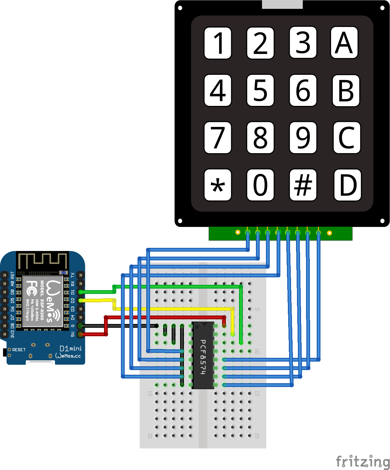
Because the used keypad in this tutorial uses 8 digital I/O pins on the microcontroller, it is useful to reduce the number of used pins with an PCF8574 I2C multiplexer.
The PCF8574 is a 8-bit input/output (I/O) expander for I2C, that uses only two pins for the communication. If you wan to learn more about the multiplexer and the I2C communication, you can visit my I2C tutorial article.
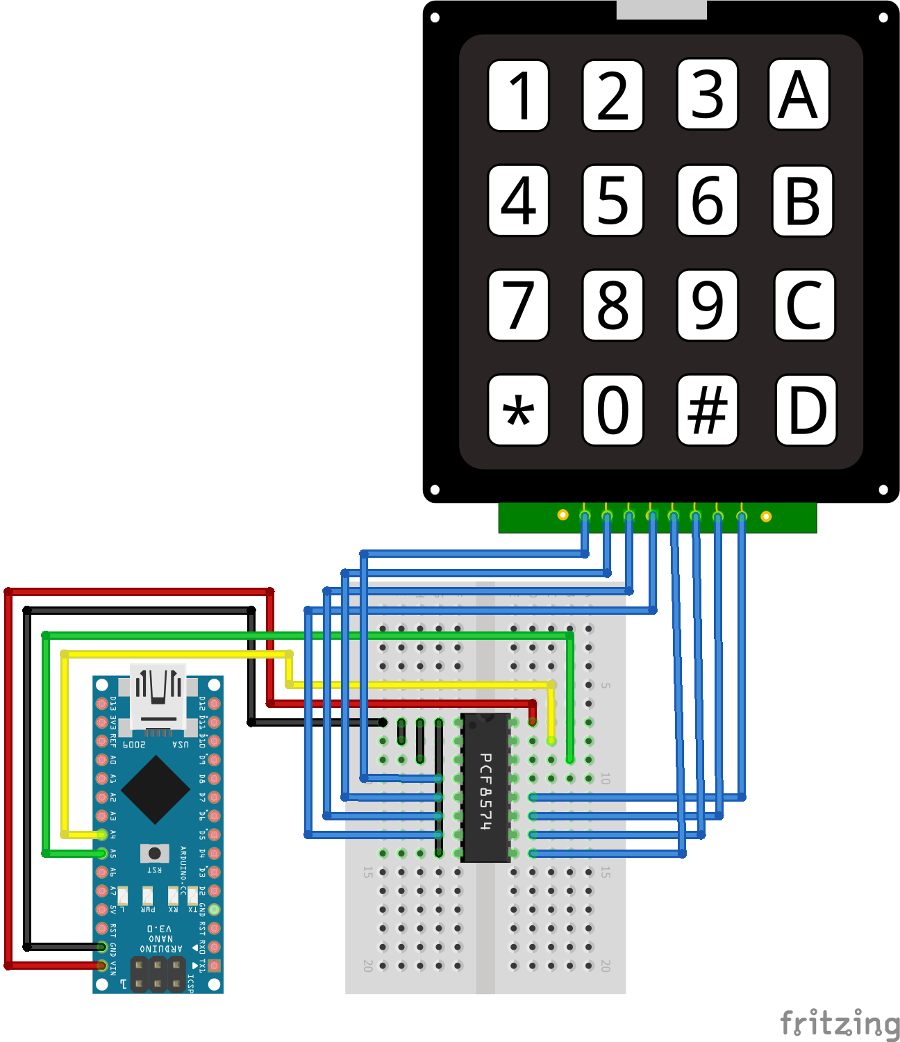
The picture on the right side shows the pins of the PCF8574 and the following picture shows the wiring between the Arduino, ESP8266 or ESP32 microcontroller, the I2C multiplexer and the keypad.

I2C Multiplexer Keypad Arduino Nano

I2C Multiplexer Keypad Arduino Pro Mini
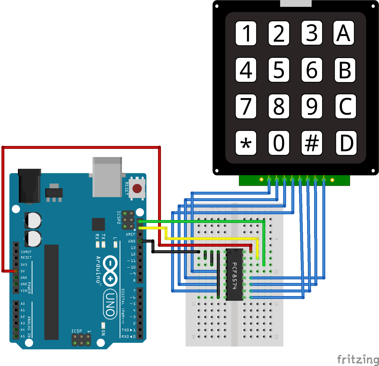
I2C Multiplexer Keypad Arduino Uno
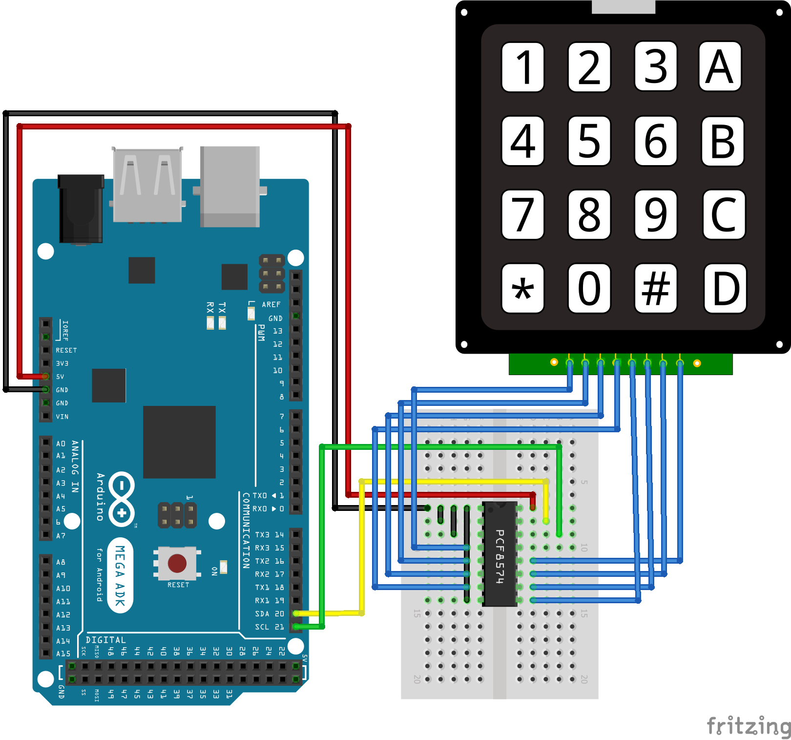
I2C Multiplexer Keypad Arduino Mega
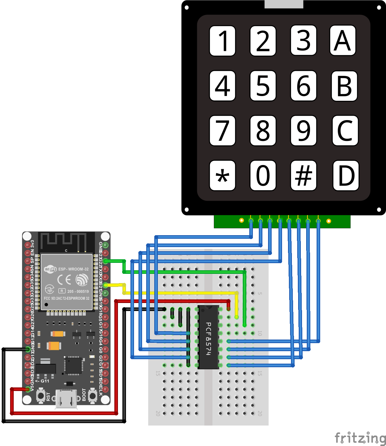
I2C Multiplexer Keypad ESP32 NodeMCU
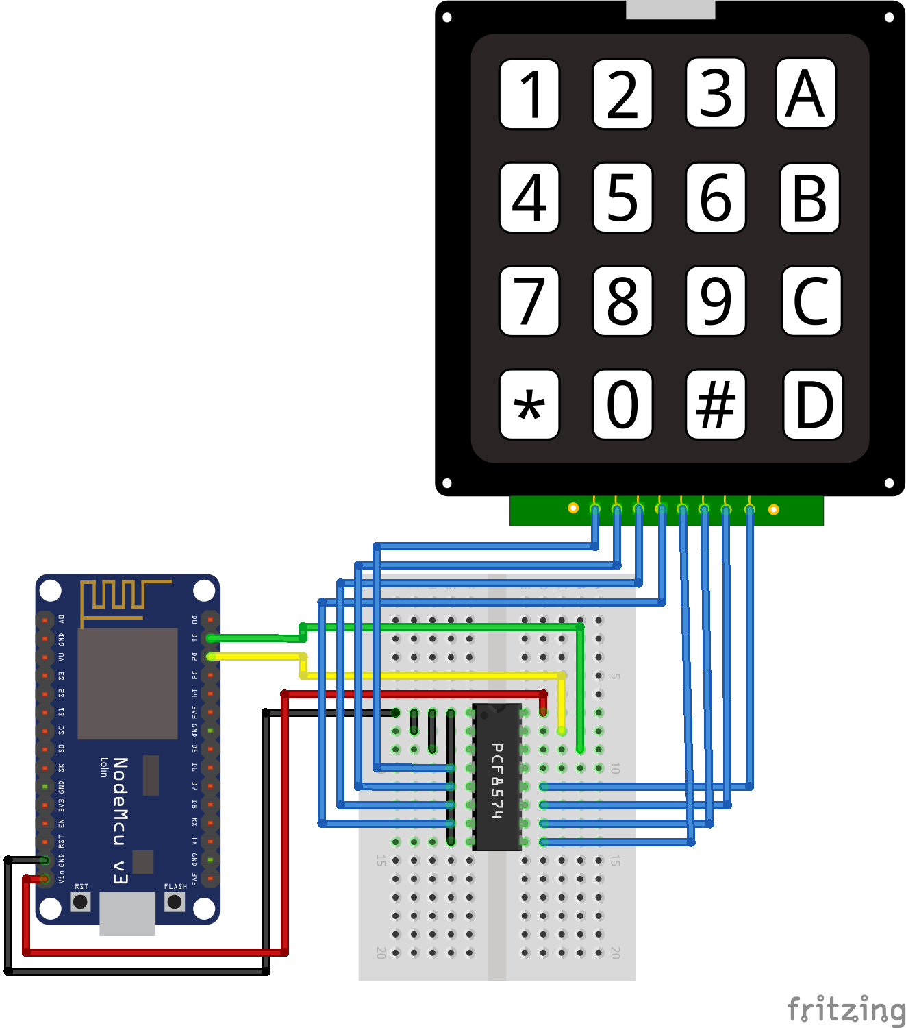
I2C Multiplexer Keypad ESP8266 NodeMCU
I2C Multiplexer Keypad ESP8266 WeMos D1 Mini
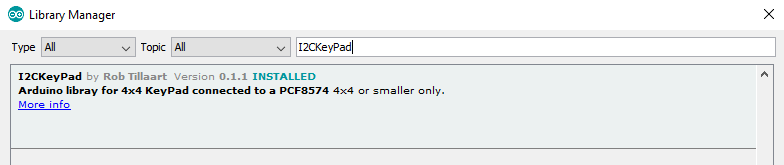
For the program script we need to install the I2CKeyPad library of Rob Tillaart that you find in the Library Manager of the Arduino IDE.
In the following section, we go over the program code to use the I2C expander in combination with the keypad. Because we do not use microcontroller specific pins, the program code is valid for Arduino, ESP8266 and ESP32.
#include "Wire.h"
#include "I2CKeyPad.h"

const uint8_t KEYPAD_ADDRESS = 0x20;
uint8_t lastKey;

I2CKeyPad keyPad;

void setup()
{
  Serial.begin(115200);
  Wire.begin();
  Wire.setClock(400000);
  if (keyPad.begin(KEYPAD_ADDRESS) == false)
  {
    Serial.println("\nERROR: cannot communicate to keypad.\nPlease reboot.\n");
    while(1);
  }
}

void loop()
{
  char keys[] = "123A456B789C*0#DNF";  // N = Nokey, F = Fail

  uint8_t idx = keyPad.getKey();
  if (idx != lastKey & keys[idx] != 'N') {
    Serial.println(keys[idx]);
    lastKey = idx;
    }
  delay(100);
}
In the first part of the program script we include the Wire library, to communicate via I2C and the I2CKeyPad library that helps us to map the keypad signals on the I2C communication protocol.
After we included the libraries we have to define the I2C HEX address of the PCF8574. In most cases the address should be 0x20 but you can use the I2C HEX address scanner from the I2C tutorial to quickly find the address.
Now we create an I2CKeyPad object called keyPad and also define a variable to store the last pressed position on the keypad, called lastKey. The datatype of uint8_t is an unsigned integer of length 8 bits.
In the setup function the baud rate is set to 115200 that have to match to the baud rate of the serial monitor if we later wan to see the pressed key. After the I2C communication is initialized the clock speed of the I2C is set to 400000 and we define an error catch if the HEX address is not the right one.
In the loop function we first create an array of the keys on the keypad. In my case I have a 4×4 keypad. The last two entries helps us to get values of the library if there is no key pressed or the readout of the keypad failed. With the getKey function we store the current pressed place on the keypad in the variable idx.
In the if condition we define that only the current key is pressed, when the key is a different from the previous one and only if there is a key pressed. Therefore we look up the pressed key in the keys array with the position of the keypad that is stored in variable idx. In the last step we save the current position of the keypad in the lastKey variable and set a small delay of 0.1 seconds.
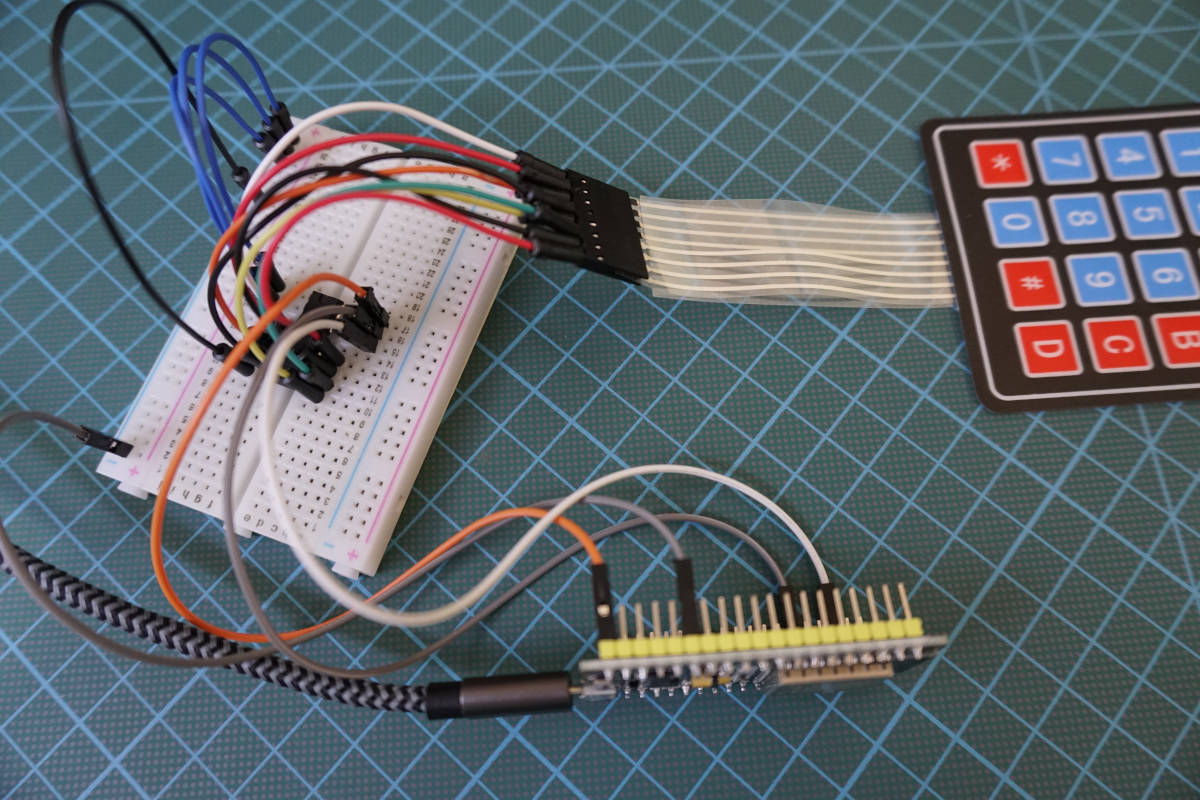
The output of the I2C multiplexer is the same like you are not using the multiplexer. But you can save a lot of digital I/O pins on your microcontroller. The following picture shows the example with the I2C multiplexer.
Conclusion
I hope you liked this tutorial where you learned how to use the keypad as input device and build a lock which opens when we type in the correct password. If you want to reduce the number of used digital I/O pins, I recommend to read the article about the digital multiplexer.
What is your next project and will you use the keypad? Let me know in the comment section.
If you have any questions regarding this tutorial, use the comment section below to ask your questions. I answer them as soon as possible.
Great work. Is it possible to expand this to 5×5 using the ESP8266?
Hi Matt,
in my opinion it is possible to extend the keypad to a 5×5, but then I would use the PCF8574 I2C multiplexer to reduce the number of needed digital pins on the ESP8266.
Good Job!!!
Thanks Jackson
Hi i would like to make remote control 12 relay with momentary switches with this key board over long distance with rs 485, how i can do it ?
How can I set the pin code in firebase realtime database so it can be easily updated? Thanks John
For ESP32 Microcontroller pin 21 used twice. Right?
Hi Enschy,
that was a copy past mistake from my side but I corrected it.
Hi Sir,
Complete beginner here.
I have an MH-ET LIVE ESP32 board and the pinout is different than all your examples.
Can you please add the MH-ET LIVE pinout to the examples?