Soil Moisture Sensor Tutorial for Arduino, ESP8266 and ESP32
In this tutorial we measure the soil moisture with a soil moisture sensor.
Because there are two different types of sensors, we describe the functionality of each one in the first chapter.
After you learn how to wire the sensor to your Arduino, ESP8266 or ESP32 microcontroller board, we create a basic Arduino script.
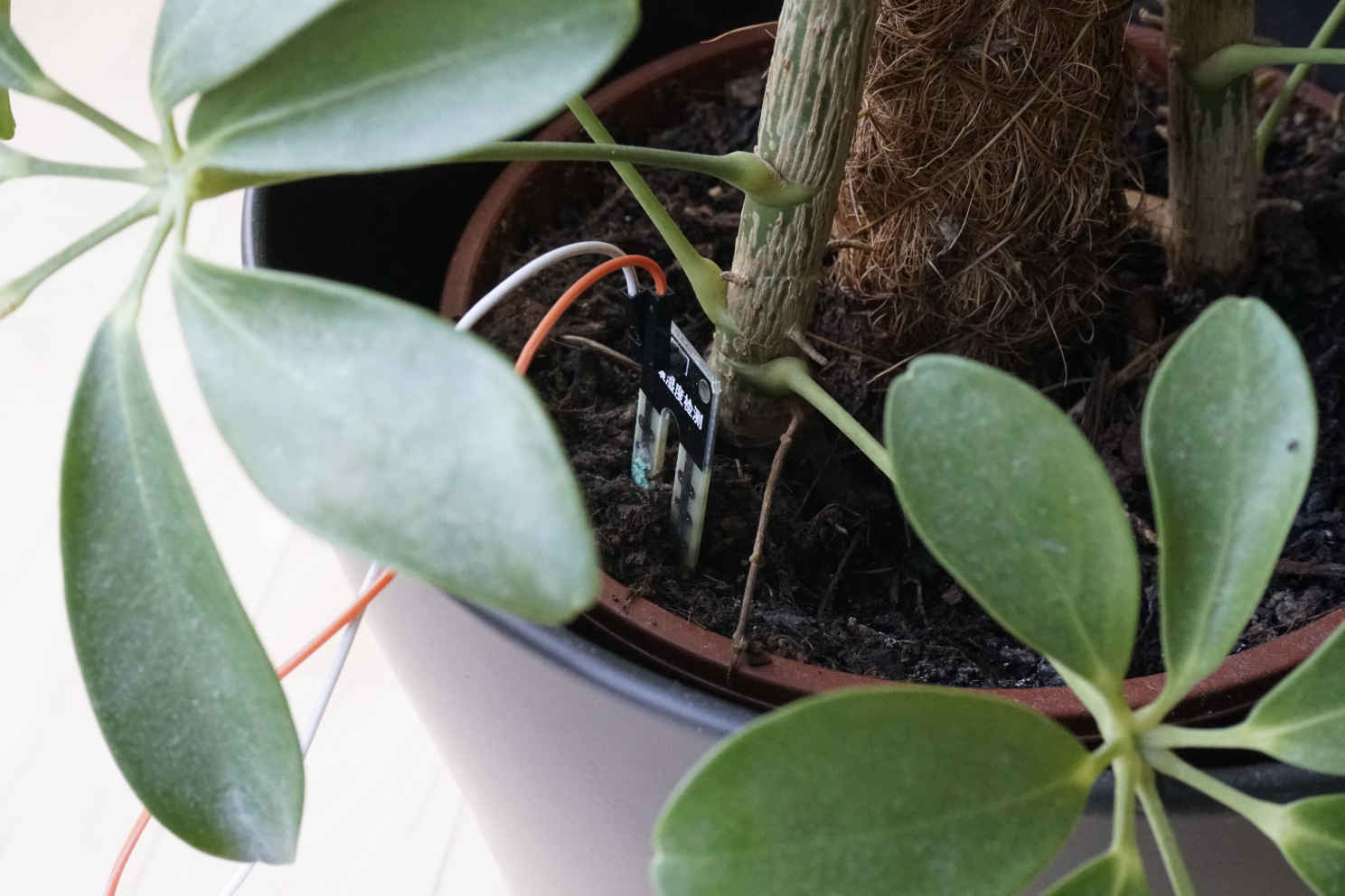
The last part of this tutorial I show you a practical example with Arduino, ESP8266 or ESP32 microcontrollers. In this example I measured the soil moisture of an orchid plant over 2 weeks.
Table of Contents
How the sensor measures the soil moisture?
As describes in the introduction, there are two different types of soil moisture sensors. Therefore the first step of this tutorial is to describe the functionality of each one and also to make sure that you buy the right sensor, if you not already have a soil moisture sensor.
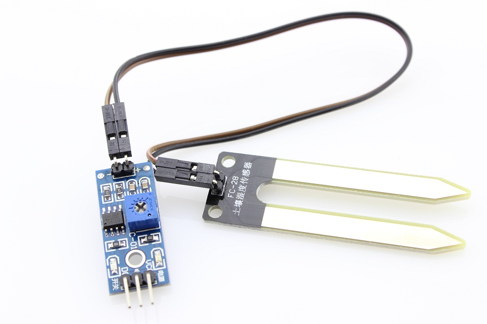
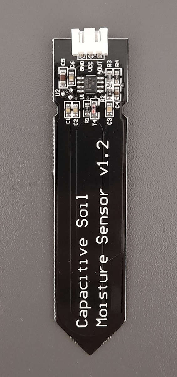
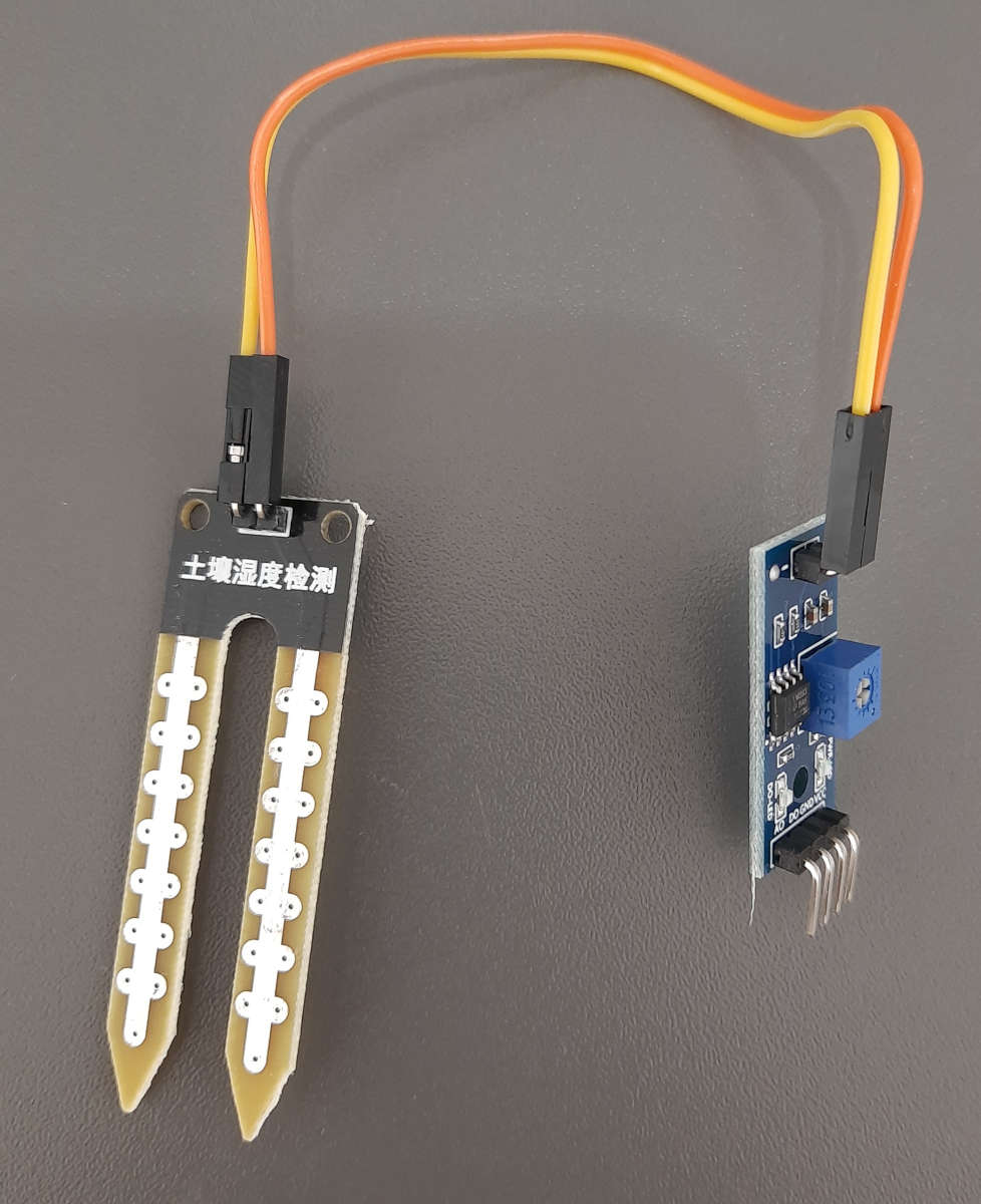
The following two pictures show a photo of each sensor.
Capacitive Soil Moisture Sensor
- Long lifetime and no corrosion
- Works only with 5V operation voltage
Resistive Soil Moisture Sensor
- Works with 3.3V and 5V operation voltage
- Works only several days due to corrosion
Capacitive Soil Moisture Sensor
The capacitive soil moisture sensor does not measure moisture directly but measures the changes in capacitance caused by the changes in the dielectric contrast between water and soil. Dry soils have a relative permittivity between 2-6 and water has a value of roughly 80.
The major advantage of the capacitive sensor is that there is no direct exposure of the metal electrodes. Therefore there is no electrolysis that damages the sensor through corrosion.
The operation voltage of the capacitive soil moisture sensor is 5V from my experience. In some datasheets you find the declaration that the sensor also works for 3.3V microcontrollers but in the sub chapter Influence of the Power Supply on the Analog Sensor Value, you see that I got invalid sensor values.
If you want to buy a soil moisture sensor, make sure that you buy a capacitive one.
Resistive Soil Moisture Sensor
The resistive soil moisture sensor consists of 2 probes with are put in the soil. Depending on the current direction one probe will function as the cathode and the other one as anode. Generally which probe is the anode or cathode is irrelevant for the functionality of the sensor, because the sensor only measures the resistance and is therefore independent of the direction of the current flow.
The electrical circuit is closed over the soil which functions as resistance for the current flow. This resistance is measured and depends on the amount of water in the soil because water is a natural conductor for electricity. The lower the measured resistance, the higher is the amount of water in the soil.
The current flow through the anode of the resistive soil moisture sensor, which has contact to water, is a perfect environment for electrolysis and therefore electroplating. This electrolysis damages the sensor and makes the sensor inaccurate. How strong the electrolysis will be depends on how often and how much current is passed through the electrodes.
Wiring between Soil Moisture Sensor and Microcontroller
The following pictures show the wiring between the soil moisture sensor and an the most used microcontroller from Arduino, ESP32 and ESP8266. If you are missing your favorite microcontroller, let me know in the comment section and I will add the wiring also your this microcontroller board.
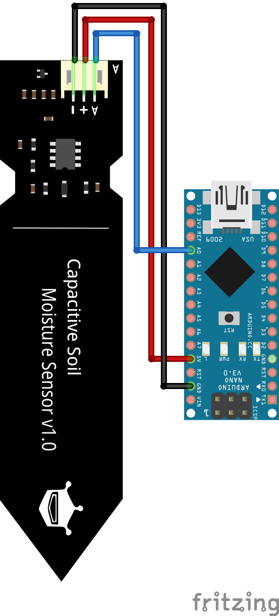
Soil Moisture Sensor Arduino Nano

Soil Moisture Sensor Arduino Pro Mini
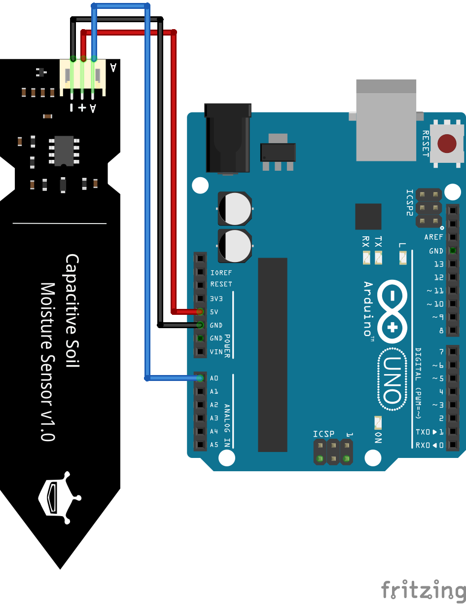
Soil Moisture Sensor Arduino Uno
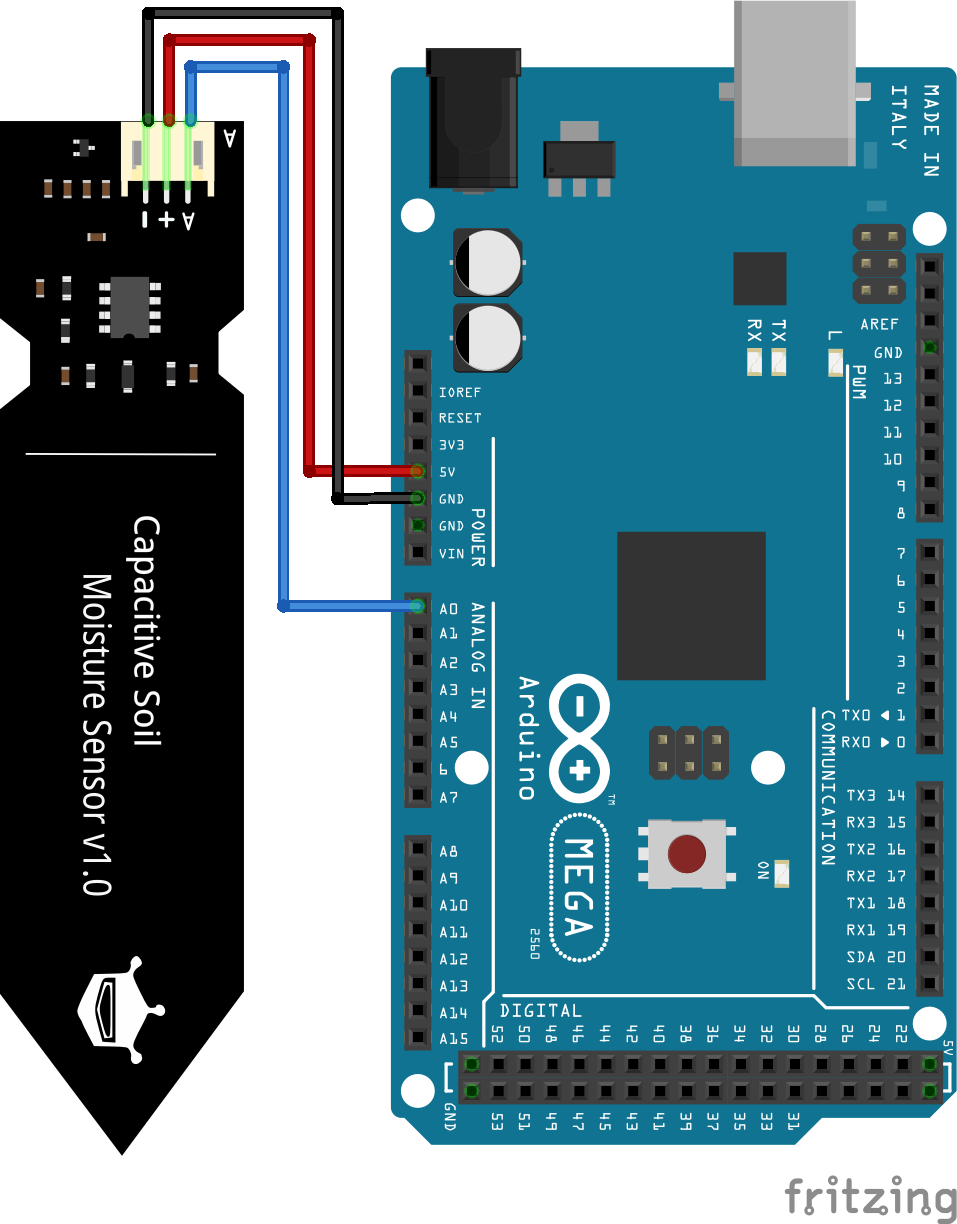
Soil Moisture Sensor Arduino Mega
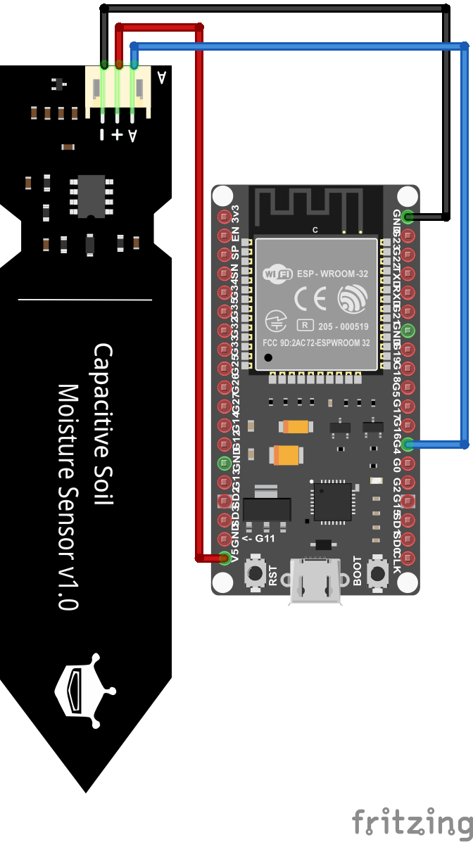
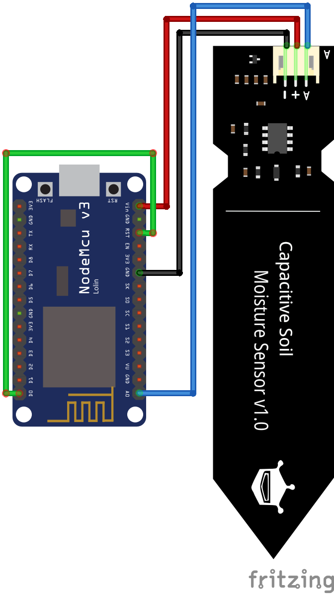
Soil Moisture Sensor ESP32 NodeMCU
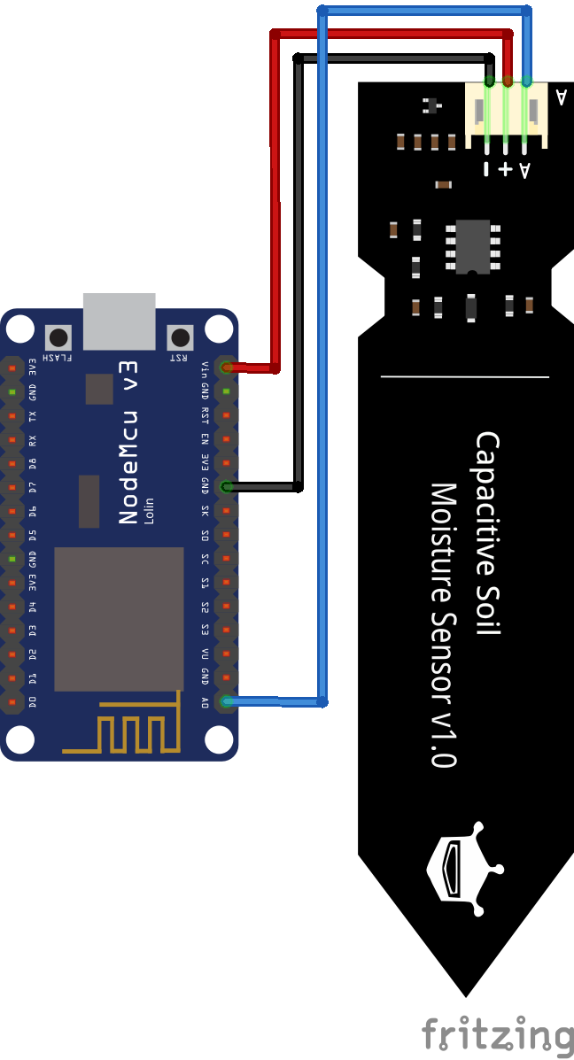
Soil Moisture Sensor ESP8266 NodeMCU
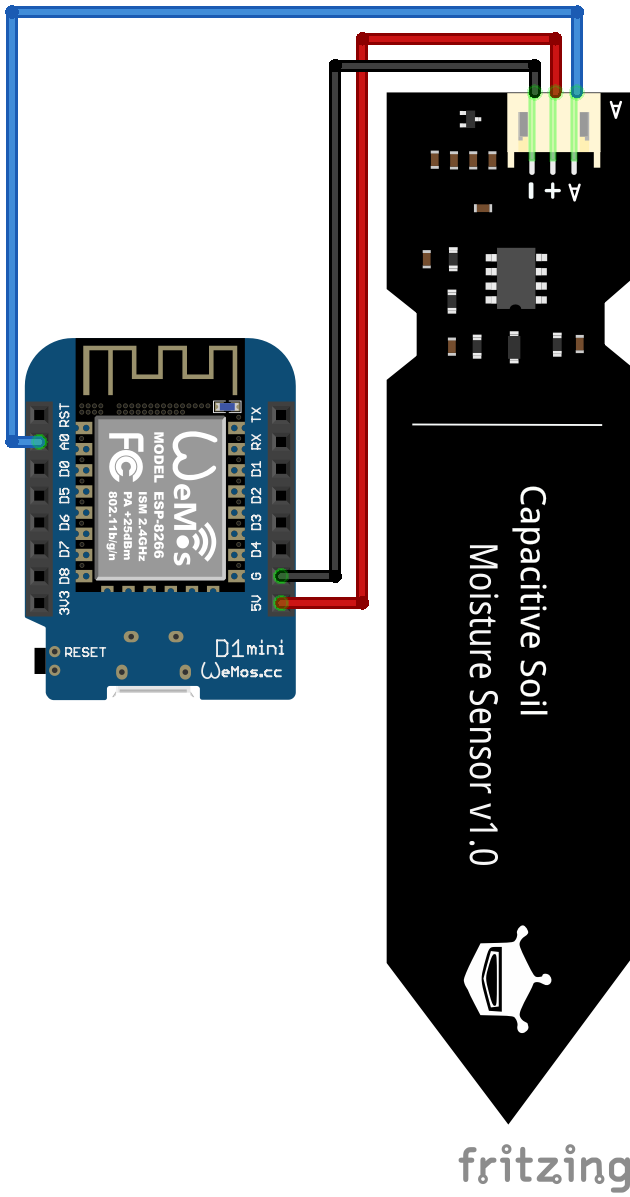
Soil Moisture Sensor ESP8266 WeMos D1 Mini
Influence of the Power Supply on the Analog Sensor Value
The capacitive and also the resistive soil moisture sensor works with supply voltages between 3.3V and 5V. Therefore you can use the Arduino (5V operating voltage) and also the ESP (3.3V operating voltage) based microcontroller to measure the soil moisture.
But you have to keep in mind that the analog sensor value is dependent on the operating voltage. The following table shows the analog sensor value for all different combination of operating voltage, moisture and type of soil moisture sensor.
Theoretically you can use any of these combinations, but you have to calibrate your sensor before you declare that your soil is wet or dry.
For the capacitive soil moisture sensor you see also from the table that the difference in the sensor value for an operating voltage of 3.3V is very low. Therefore your measuring range is very close and I recommend to use an operating voltage of 5V for the capacitive sensor.
Arduino Code to read the Analog Value of the Soil Moisture Sensor
The following Arduino script reads the analog sensor value of the soil moisture sensor. The script is prepared for Arduino, EPS8266 and ESP32 microcontroller boards. You only have to comment the parts that you do not need based on my comments in the script.
#define SensorPin A0  // used for Arduino and ESP8266
//#define SensorPin 4  // used for ESP32

void setup() {
  Serial.begin(9600);
}

void loop() {
  float sensorValue = analogRead(SensorPin);
  Serial.println(sensorValue);
  delay(30000);
}
In the first part of the script we define the analog pin that connects the microcontroller with the soil moisture sensor. For the Arduino and ESP8266 we use the A0 pin. Because every digital I/O pin of the ESP32, that is not used for a communication interface, can be an analog input we have to choose one pin as analog input. In my case I use the pin 4.
If you are not sure what pins of the ESP32 board can be used as analog inputs, I recommend to download the Microcontroller Datasheet Playbook where you find detailed pinouts of several microcontroller boards, including the ESP32.
In the setup function we define the baud rate to 9600 that has to match the baud rate of the serial monitor of the Arduino IDE.
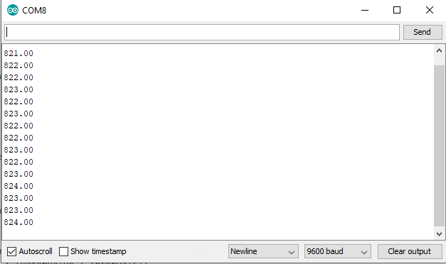
The loop function starts with reading the analog sensor value of the analog pin that we defined that the beginning of the script. The sensor value is stored in a variable from the type float. Now we print the sensor value to the serial monitor and wait for 30 seconds to start to loop function all over again.
The following picture shows the sensor values in the serial output.
Expand the Lifetime of the Resistive Soil Moisture Sensor
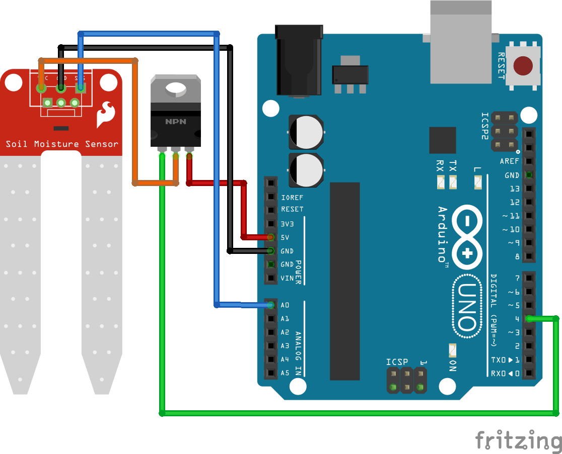
As described in the functionality chapter of this tutorial, electrolysis of the resistive soil moisture sensor is caused by the current flow through the anode. To avoid the current flow to the sensor, we use a N-Channel MOSFET circuit to disconnect the sensor from the power supply. Also we read the sensor value only once per hour.
Because we do not want to wait one hour to get a new sensor value, we use a delay of 30 seconds in the following example. Therefore you only have to change the delay for your project.
The following picture shows the N-Channel MOSFET circuit with the soil moisture sensor for the different microcontroller boards.
#define SensorPin A0

void setup() {
  Serial.begin(9600);
  pinMode(4, OUTPUT);
}

void loop() {
  digitalWrite(4, HIGH);
  delay(1000);

  float sensorValue = analogRead(SensorPin);
  Serial.println(sensorValue);
  delay(1000);
  digitalWrite(4, LOW);
  delay(28000);
}
At the beginning of the Arduino script we define the analog pin of the microcontroller. For the Arduino and ESP8266 boards we use the A0 pin and for the ESP32 we define pin 4 as analog input.
In the setup function we set the baud rate to 9600, that have to match the baud rate of the Arduino IDE to see the sensor values that we want to print on the serial connection between microcontroller and PC.
Also we define the digital output pin that is connected to the gate of the MOSFET to switch the sensor on and off. For the Arduino boards we use digital pin 4, for ESP8266 pin D4 and for ESP32 pin 0 as digital output pin. You only have to comment the lines for the microcontroller that you do not need.
In the loop function we read the moisture sensor value every 30 seconds. Therefore we use die digital pin to enable the current flow on the gate of the MOSFET. This closes the circuit of the soil moisture sensor and we read the analog sensor value after a short delay of 1 second. After the sensor value is printed to the serial monitor, we wait for 1 second and disable the current flow through the sensor by pulling the Gate of the MOSFET LOW.
Because we want to read the sensor value every 30 seconds in this example and already have two 1 second delays in the Arduino script, we wait for 28 seconds at the end of the program code.
MQTT Example for Long Term Monitoring
In the following example I want to observe the soil moisture for a plant for a long time and see the course of the moisture as a line-chart. Therefore I build a MQTT system including the following components:
- NodeMCU to read the analog soil moisture sensor values and send them every hour via MQTT to a MQTT broker
- Raspberry Pi as MQTT broker which saves the moisture values to an Influx database and visualize the soil moisture of the plan via Grafana.
The following table gives you an overview of all components and parts that I used for this example. I get commissions for purchases made through links in this table.
This example relates strongly on two articles I wrote the last month. Therefor I will speed up this example because you find a step by step tutorial in the following two articles:
- Microcontroller to Raspberry Pi WiFi MQTT communication
- Visualize MQTT Data with InfluxDB and Grafana
At the end of this article you can download all scripts, compressed as zip file, for this example with the blue download button.
First we build the part of the NodeMCU to send the sensor values to the MQTT broker. The following picture shows the wiring for the NodeMCU.
The program code is nearly exactly the same as I used to send the temperature and humidity to the MQTT broker. I only changed the MQTT topic, MQTT clientID and read the moisture values to send them via MQTT to the same existing broker. The main code is inside the setup function, because I use the deep-sleep function of the NodeMCU to reduce the electrolysis on the soil moisture sensor.
Make sure you add the delay before entering the deep-sleep. I had some problems, that the NodeMCU shutting down while the MQTT message was not completely send.
#include "ESP8266WiFi.h" // Enables the ESP8266 to connect to the local network (via WiFi)
#include "PubSubClient.h" // Allows us to connect to, and publish to the MQTT broker

#define SensorPin A0

// WiFi
const char* ssid = "KabelBox-0174";
const char* wifi_password = "943476385562******";

// MQTT
// Make sure to update this for your own MQTT Broker!
const char* mqtt_server = "192.168.0.8";
const char* plant_topic = "plant";
const char* mqtt_username = "cdavid";
const char* mqtt_password = "cdavid";
// The client id identifies the ESP8266 device. Think of it a bit like a hostname (Or just a name, like Greg).
const char* clientID = "client_plant_test";


// Initialise the WiFi and MQTT Client objects
WiFiClient wifiClient;
PubSubClient client(mqtt_server, 1883, wifiClient); // 1883 is the listener port for the Broker


void connect_MQTT(){
  Serial.print("Connecting to ");
  Serial.println(ssid);

  // Connect to the WiFi
  WiFi.begin(ssid, wifi_password);

  // Wait until the connection has been confirmed before continuing
  while (WiFi.status() != WL_CONNECTED) {
    delay(500);
    Serial.print(".");
  }

  // Debugging - Output the IP Address of the ESP8266
  Serial.println("WiFi connected");
  Serial.print("IP address: ");
  Serial.println(WiFi.localIP());

  // Connect to MQTT Broker
  // client.connect returns a boolean value to let us know if the connection was successful.
  // If the connection is failing, make sure you are using the correct MQTT Username and Password (Setup Earlier in the Instructable)
  if (client.connect(clientID, mqtt_username, mqtt_password)) {
    Serial.println("Connected to MQTT Broker!");
  }
  else {
    Serial.println("Connection to MQTT Broker failed...");
  }
}


void setup() {
  Serial.begin(9600);
  connect_MQTT();
  Serial.setTimeout(2000);

  float sensorValue = analogRead(SensorPin);
  Serial.println(sensorValue);

  // PUBLISH to the MQTT Broker
  if (client.publish(plant_topic, String(sensorValue).c_str())) {
    Serial.println("Moisture sent!");
    Serial.println(plant_topic);
  }
  // Again, client.publish will return a boolean value depending on whether it succeded or not.
  // If the message failed to send, we will try again, as the connection may have broken.
  else {
    Serial.println("Moisture failed to send. Reconnecting to MQTT Broker and trying again");
    client.connect(clientID, mqtt_username, mqtt_password);
    delay(10); // This delay ensures that client.publish doesn't clash with the client.connect call
    client.publish(plant_topic, String(sensorValue).c_str());
  }

  delay(1000);
  ESP.deepSleep(0.2*60e6);
}

void loop() {
}
Now the NodeMCU sends the current soil moisture every hour to the MQTT broker. The next task is to write a bridge script which reads the MQTT payload and writes it to the Influx Database.
I created a new Influx database called “soil_moisture” and a new Influx user “mqtt_moisture” with the password “mqtt_moisture”. Also I granted all rights for this new database to the new user.
Again the script is nearly the same I used for the indoor weather stations. You find the corresponding article here. You can copy the following python script for your MQTT bridge script or download the python file with the following download button.
import re
from typing import NamedTuple
import paho.mqtt.client as mqtt
from influxdb import InfluxDBClient
INFLUXDB_ADDRESS = '192.168.0.8'
INFLUXDB_USER = 'mqtt_moisture'
INFLUXDB_PASSWORD = 'mqtt_moisture'
INFLUXDB_DATABASE = 'soil_moisture'
MQTT_ADDRESS = '192.168.0.8'
MQTT_USER = 'cdavid'
MQTT_PASSWORD = 'cdavid'
MQTT_TOPIC = 'plant'
MQTT_CLIENT_ID = 'MQTTInfluxDBBridge_moisture'
influxdb_client = InfluxDBClient(INFLUXDB_ADDRESS, 8086, INFLUXDB_USER, INFLUXDB_PASSWORD, None)
def on_connect(client, userdata, flags, rc):
""" The callback for when the client receives a CONNACK response from the server."""
print('Connected with result code ' + str(rc))
client.subscribe(MQTT_TOPIC)
def on_message(client, userdata, msg):
"""The callback for when a PUBLISH message is received from the server."""
print(msg.topic + ' ' + str(msg.payload))
sensor_data = float(msg.payload)
if sensor_data is not None:
_send_sensor_data_to_influxdb(sensor_data)
def _send_sensor_data_to_influxdb(sensor_data):
json_body = [
{
'measurement': 'soil_moisture',
'tags': {
'location': 'livingroom'
},
'fields': {
'value': sensor_data
}
}
]
influxdb_client.write_points(json_body)
def _init_influxdb_database():
databases = influxdb_client.get_list_database()
if len(list(filter(lambda x: x['name'] == INFLUXDB_DATABASE, databases))) == 0:
influxdb_client.create_database(INFLUXDB_DATABASE)
influxdb_client.switch_database(INFLUXDB_DATABASE)
def main():
_init_influxdb_database()
mqtt_client = mqtt.Client(MQTT_CLIENT_ID)
mqtt_client.username_pw_set(MQTT_USER, MQTT_PASSWORD)
mqtt_client.on_connect = on_connect
mqtt_client.on_message = on_message
mqtt_client.connect(MQTT_ADDRESS, 1883)
mqtt_client.loop_forever()
if __name__ == '__main__':
print('MQTT to InfluxDB bridge Moisture')
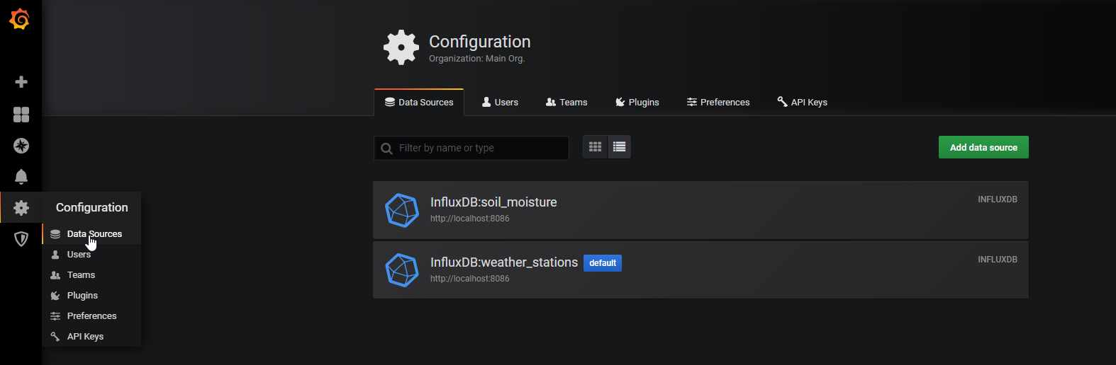
main() Now the sensor values are stored in the Influx database so that we can create a dashboard in Grafana. In Grafana you can create a new data source. Use the Influx database and the username and password you set before.
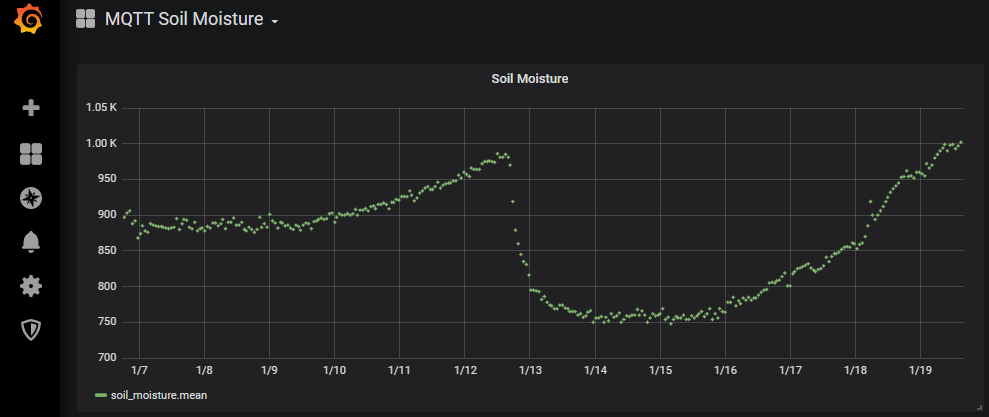
Now you can create a new dashboard and visualize the soil moisture of your plants at home. The following picture is the one I collected the data over several days. You see clearly how the sensor values are rising to 980 over the days. Between the 12.01. and 13.01 the plant got some water and the sensor values drop to around 750. In the following days the sensor values rise again and now I know exactly when my plant needs water.
Conclusion
I hope with this tutorial you now have a good understanding of the soil moisture sensor. I tried to keep the theory of the sensor as short as possible because the functionality of the sensor is not very complex to understand. Therefor I tried to concentrate on a good practical example using MQTT, InfluxDB and Grafana to build a pretty monitoring system for your plants at home.
I hope you like this article. If you have any questions regarding the moisture sensor or the MQTT example please use the comment section below to ask your questions. I answer them as soon as possible.
Hi there,
Thank you very much for your well-written tutorials! I have been having fun following along from here in America :).
Through the articles you have written, I was able to get mostly set up, aside from one issue.
My device only seems to report when I first plug it in. Do you have any ideas why?
Also, the code (I believe) is missing some information here:
#include // Enables the ESP8266 to connect to the local network (via WiFi)
#include // Allows us to connect to, and publish to the MQTT broker
I made it the below. Is this correct?
#include // Enables the ESP8266 to connect to the local network (via WiFi)
#include // Allows us to connect to, and publish to the MQTT broker
Hi Jarrod,
yes there is a missing part in the include line because the editor of this website has problems to print <>. Therefore I changed the include lines to #include “ESP8266WiFi.h” and #include “PubSubClient.h” that also works fine in Arduino.
Regarding your problem, that your device only reports when you plug it in: What is the content of your loop function?
Thanks for the fast response!
I am using your code:
}
delay(1000);
ESP.deepSleep(0.2*60e6);
}
void loop() {
}
Hi Jarrod,
ok your ESP should wake-up every 0.2*60 = 12 seconds.
Do you connect the D0 and RST pin after flashing the microcontroller?
I got it… I didn’t have a wire going from D0 to RST! Thanks for your help! I am now getting data every 12 seconds.
So, if I wanted a reading every 30 minutes to preserve power, I should change
0.2*60 to 0.2*9000?
Perfect! If you want to send the data every 30 minutes you have to replace the 0.2*60 with 30*60, because the ESP.deepSleep function get as argument the time in microseconds. By multiply your time with 60e6 you get the time in minutes. Therefore you need 30*60e6 as argument.
Hi!
I got everything to work as described above with very little problems. It seems as I even had the same or very similar soil probe as in your images.
My problem is that there is still current to the soil probe during the deep sleep, so the probe is consumed after ~3 weeks.
I’m using a NodeMcu V3 with your example program.
I put in a few extra lines in the code to assure the NodeMcu goes into deep sleep, and it seems so.
I can measure ~73 mA (with a very old digital multimeter), to the probe sensor logic board during deep sleep, the led is still bright. Since there is no metal left on one leg of the probe I guess it’s more or less correct.
Any suggestions?
Regards
Hi, I could think that maybe your NodeMCU is not going to deep sleep. Do you measured the current consumption for the NodeMCU during the deep sleep mode? Also you could use the ESP.getResetReason() function to see if the ESP comes back from deep sleep.
hello Admin
I Have a problem when I used Hassio for MQTT broker.
When Flashed code to ESP 8266, I saw data that send to broker is zero all the time
Could you please explain to me?
thanks
Hi, do you see the moisture values in the Serial Monitor of the Arduino IDE?
Thank you for your answer. My sensor has been an error and after I have replaced it, everything is well now.
Hi Mr Cuong,
thx for the reply, a general failure in the sensor is not so easy to detect. Nice to hear that now everything is working well.
Thanks a lot for this work. It really helped me get the concept well. Can I ask that you please guide me further on how to calibrate the capacitancor soil mois ture sensor?
The values I got were below your suggestions, so I felt probably it is because I have not calibrate the sensor. Thanks