ESP32 Tutorial: What do you have to know about the ESP32 microcontroller?
There is a follow-up model of the ESP8266, a very powerful microcontroller with a low purchasing price:
The ESP32 also produced by Espressif Systems.
In this tutorial you learn :
- Technical specifications of the ESP32
- Pinout of the ESP32
- Power supply of the ESP32, also including powering with a battery
- Power modes and power consumption of the ESP32
- Configure the ESP32 board in the Arduino IDE
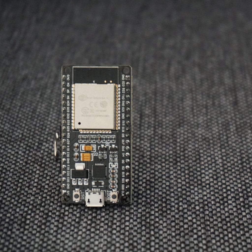
Table of Contents
What is the ESP32?
The ESP32 is a powerful 32 bit microcontroller with integrated Wi-Fi, full TCP/IP stack for internet connection and Bluetooth 4.2. Due to the low cost combined with great power and the opportunity to connect the ESP32 to many other electronic devices, the microcontroller is well suited for IoT projects.
Technical specifications of the ESP32
- TTensilica Xtensa 32-bit LX6 microprocessor with 2 cores
- Power supply: 2.3V – 3.6V
- Current consumption: 20µA – 240mA. In DeepSleep-Mode only 5µA
- Operating temperature range: -40°C – 125°C
- External flash memory: up to 16 MB is supported
- Interfaces
- UART/SDIO/SPI/I2C/I2S/IR Remote Control
- 36 programmable I/O pins max 20mA
- 2 analog input 0V to 1V with 12 bit resolution
- all inputs tolerate maximum 3.6V
- Network
- WiFi
- WiFi 802.11 b/g/n 2.4 GHz with WPA/WPA2 PSK
- ipv4 and ipv6 from Arduino Core 2.5.0
- UDP and TCP with 5 simultaneous connections as maximum
- Bandwidth: 150 to 300 kByte/s
- Latency: < 10ms
- Bluetooth: v4.2 BR/EDR and Bluetooth Low Energy (BLE)
- WiFi
If you want a full comparison of the technical specifications of the ESP32 against the ESP8266 boards and different Arduino boards, you will find this comparison in this article.
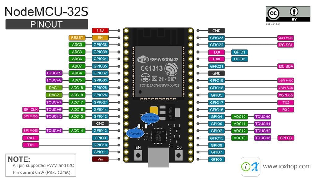
Pinout of the ESP32 NodeMCU
| NodeMCU label | Touch | PWM | Name | Description |
| 3.3V | Power supply 3.3V, 400mA | |||
| EN | ENABLE | Low = Power Down, High = Enabled, has 12kΩ pull-up | ||
| SVP | x | Digital Input pin with PWM | ||
| SVN | x | |||
| P34 | x | |||
| P35 | x | |||
| P32 | TOUCH9 | x | Digital I/O pin with touch sensor and PWM | |
| P33 | TOUCH8 | x | ||
| P25 | x | Digital-to-Analog Converter (DAC_1) | ||
| P26 | x | Digital-to-Analog Converter (DAC_2) | ||
| P27 | TOUCH7 | x | Digital I/O pin with touch and PWM | |
| P14 | TOUCH6 | x | ||
| P12 | TOUCH5 | x | ||
| GND | Ground | |||
| P13 | TOUCH4 | x | Digital I/O pin with touch and PWM | |
| SD2 | x | Digital I/O pin with PWM | ||
| SD3 | x | |||
| CMD | x | |||
| 5V | x | Power supply 5V-9V, 400mA | ||
| CLK | x | Digital I/O pin with PWM | ||
| SD0 | x | |||
| SD1 | x | |||
| P15 | TOUCH3 | x | Digital I/O pin with touch and PWM | |
| P2 | TOUCH2 | x | ||
| P0 | TOUCH1 | x | ||
| P4 | TOUCH0 | x | ||
| P16 | x | Digital I/O pin with PWM | ||
| P17 | x | |||
| P5 | x | SS | Digital I/O pin with SS (Slave Select) for SPI communication | |
| P18 | x | SCK | Digital I/O pin and SCK (Serial Clock) for SPI communication | |
| P19 | x | MISO | Digital I/O pin and MISO (Master In Slave Out) for SPI communication | |
| GND | Ground | |||
| P21 | x | Digital I/O pin with PWM | ||
| RX | x | Serial input of the ESP connected to the USB-UART | ||
| TX | x | Serial output of the ESP connected to the USB-UART | ||
| P22 | x | Digital I/O pin with PWM | ||
| P23 | x | MOSI | Digital I/O pin and MOSI (Master Out Slave In) for SPI communication | |
| GND | Ground |
Power supply of the ESP32 NodeMCU
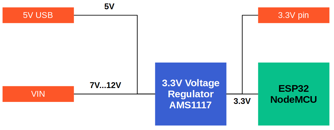
When we want to know what possibilities we have to supply power to the ESP32, we have to understand what are the different voltage levels on the PCB, starting from the supply pins and ending at the microprocessor itself.
The following picture shows a schematic picture of the voltage levels on the ESP32 NodeMCU. The additional tables show the voltage related specifications of the microprocessor and the voltage regulator.
Microcontroller | Minimum Voltage | Typical Voltage | Maximum Voltage |
ESP32 | 2.3V | 3.3V | 3.6V |
Voltage Regulator | Output Voltage | Maximum Input Voltage | Maximum Output Current |
AMS1117 | 3.3V | 15V | 1A |
The first and also the easiest possibility for a power supply is the 5V USB cable. But because the ESP32 runs on 3.3V, there is a built-in voltage regulator to transform the 5V of the USB connection to the desired 3.3V. The 3.3V pin of the NodeMCU PCB is also powered from this connection.
The second possibility is to use the VIN pin of the NodeMCU as input for the power supply. The AMS1117 voltage regulator has a maximum input voltage of 15V but in this case the regulator produces a lot of heat because the regulator has no heat sink or cooling fan for heat dissipation. Therefore a voltage between 7V and 12V is recommended when the ESP32 is powered by the VIN pin.
There are also multiple options to power the ESP32 with different kinds off batteries. This is particular interesting when you want to build a project that independent of a normal power supply like an outdoor weather station.
If the maximum voltage of the battery is higher than the maximum voltage of the ESP32 (3.6V), you have to use a voltage regulator to reduce the voltage to 3.3V. The output of the voltage regulator is then connected to the 3.3V pin of the ESP32 board.
My recommendation for a battery power supply is the LiFePO4 battery, because you do not need any extra voltage regulator between the ESP32 and the battery and they are rechargeable. Also LiFePO4 batteries have a capacity up to 6,000mAh, similar to LiPo and Li-ion batteries that gives your project a long lifetime in combination with a power mode that reduces the power consumption to a minimum.
Power modes and power consumption of the ESP32
When Wi-Fi is enabled, the chip switches between Active and Modem-sleep modes. Therefore, power consumption changes accordingly.
| Power Mode | Description | Power consumption | ||
| Active (RF working) | WiFi Tx packet | 180mA ~ 240mA | ||
| WiFi/BT Tx packet | 130 mA | |||
| WiFi/BT Rx and listening | 95mA ~ 100mA | |||
| Modem-sleep | The CPU is powered on | 240 MHz | Dual-core chip(s) | 30mA ~ 68mA |
| Single-core chip(s) | N/A | |||
| 160 MHz | Dual-core chip(s) | 27mA ~ 44mA | ||
| Single-core chip(s) | 27mA ~ 34mA | |||
| 80 MHz | Dual-core chip(s) | 20mA ~ 31mA | ||
| Single-core chip(s) | 20mA ~ 25mA | |||
| Light-sleep | 0.8mA | |||
| Deep-sleep | The ULP co-processor is powered on | 150µA | ||
| ULP sensor-monitored pattern | 100µA @1% duty | |||
| RTC timer + RTC memory | 10µA | |||
| Hibernation | RTC timer only | 5µA | ||
| Power off | CHIP_PU is set to low level, the chip is powered off. | 0.1µA |
RTC = Real Time Clock
ULP co-processor = Ultra-Low-Power Co-processor
Active mode
The chip radio is powered on. The chip can receive, transmit, or listen.
Modem-sleep mode
The CPU is operational and the clock is configurable. The Wi-Fi/Bluetooth base-band and radio are disabled. In Modem-sleep mode, the CPU frequency changes automatically. The frequency depends on the CPU load and the peripherals used.
Light-sleep mode
The CPU is paused. The RTC memory and RTC peripherals, as well as the ULP co-processor are running. Any wake-up events (MAC, host, RTC timer, or external interrupts) will wake up the chip.
Deep-sleep mode
Only the RTC memory and RTC peripherals are powered on. Wi-Fi and Bluetooth connection data are stored in the RTC memory. The ULP co-processor is functional.
Hibernation mode
The internal 8 MHz oscillator and ULP co-processor are disabled. The RTC recovery memory is powered down. Only one RTC timer on the slow clock and certain RTC GPIOs are active. The RTC timer or the RTC GPIOs can wake up the chip from the Hibernation mode.
Select the ESP32 board in the Arduino IDE
- Make sure you have the latest version of the Arduino IDE installed. You can download the last version of the official website.
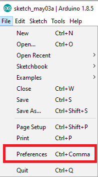
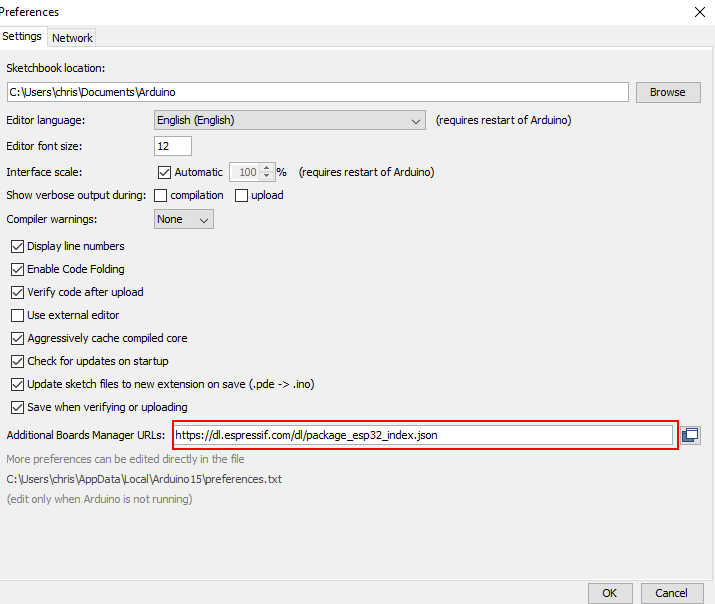
- The Arduino IDE supports a whole range of different Arduino boards after installation. Since we do not want to program an Arduino board but the NodeMCU board we have to introduce the NodeMCU board to the IDE. This is quite easy. Just klick on File → Preferences. Insert the following URL for the Additional Board Manager URLs.
https://dl.espressif.com/dl/package_esp32_index.json
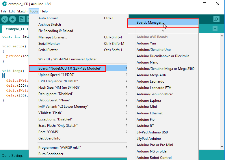
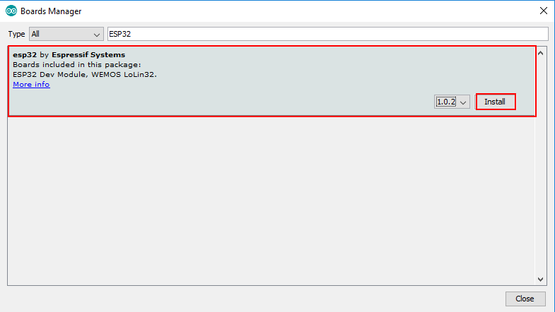
- Now we have to install the ESP32 drivers. Open the boards manager and go to Tools > Board > Boards Manager. Search for ESP32 and press install button for the “ESP32 by Espressif Systems“
Conclusion
In my opinion the ESP32 is a powerful microcontroller compared with an intuitive handling if you are familiar with the ESP8266. The only downside in my opinion is the width of the board because like the NodeMCU V3 it does not fit on the standard breadboard. Do you tried the ESP32 and what do you think about it? Leave a comment below.
This was very helpful, I was looking for the power requirements of the ESP32 and you made it very clear. Assuming your right about the 9V on the 5V pin, my ESP32 won’t start generating magic smoke. I have also ordered some ESP32 modules to integrate into my own circuits, these are 3.3 volts only, but again if your figures are right I might be able to power it with 2 x AAA rechargeable batteries at 2.4V, will be interesting to see how low the batteries can go before the module becomes unstable.
Hi, based on your comment I did a more in depth analysis of battery power supply options of the ESP32 and also added all the information to this article. Based on my analysis the best battery power supply for your case is the LiFePO4 battery (nominal voltage of 3.2V), because you do not need any extra voltage regulator between the ESP32 and the battery, they are rechargeable and you only need to wire the battery to the 3.3V pin of the ESP32 NodeMCU.
Nice info. Currently I working with this board. This board has a brother which looks like same, there is ESP-32S. The difference is this board has 38 pins and his brother 30 pins
Hi thanks for the response and you are right there is the ESP-32S on the market. I already have the NodeMCU with this chip and currently I am writing on an article how to reduce the current consumption of the ESP32 boards. One point is if it is better to use the ESP-32 or ESP-32S chip. After I published the article, I will also add the information to the ESP32 tutorial.
I try to use this board to switch a PC on. It is powered with a 12 V power supply (maybe later I’ll try the LiPo). I have an App which works fine with the corresponding Arduino script for the board. So power is on, WIFI is on, but it seems that after a while the board switches off or goes into one of the sleep modes and it is no longer available in the WIFI network. When I restart it (power off/power on) everything works fine again. Any idea what’s going on here?
Hi Martin,
I understand your use case but from the information, it is hard to detect an error. If you like, you can send me your script to the following E-Mail address, and maybe I can find an error: contact@diyi0t.com
Thanks for a great page with very useful information. Somewhere, I got the idea that if you supplied power to Vin you cause a problem if you connected a USB cable for communication. I plan using the ESP32 on a project to interface to a 1984 Heathkit H-89 Z80 based system. The ESP32 would be powered from the 5v power in the H-89. I would need to connect the USB cable to upload code while I’m debugging the design.
Thanks for any insight.
Darrell