

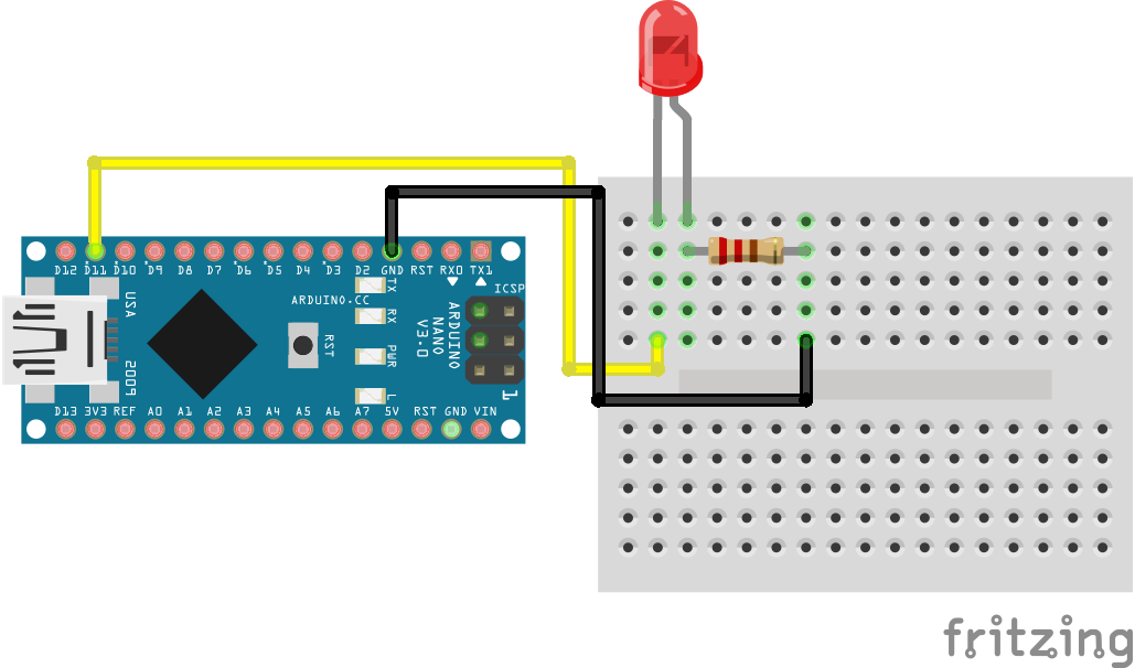
PWM LED Arduino Nano
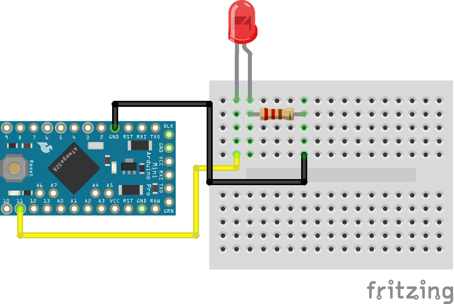
PWM LED Arduino Pro Mini
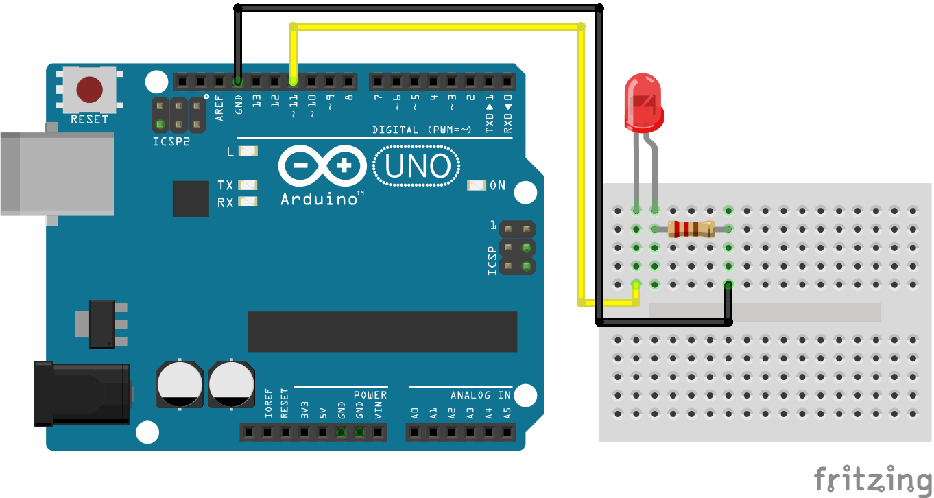
PWM LED Arduino Uno
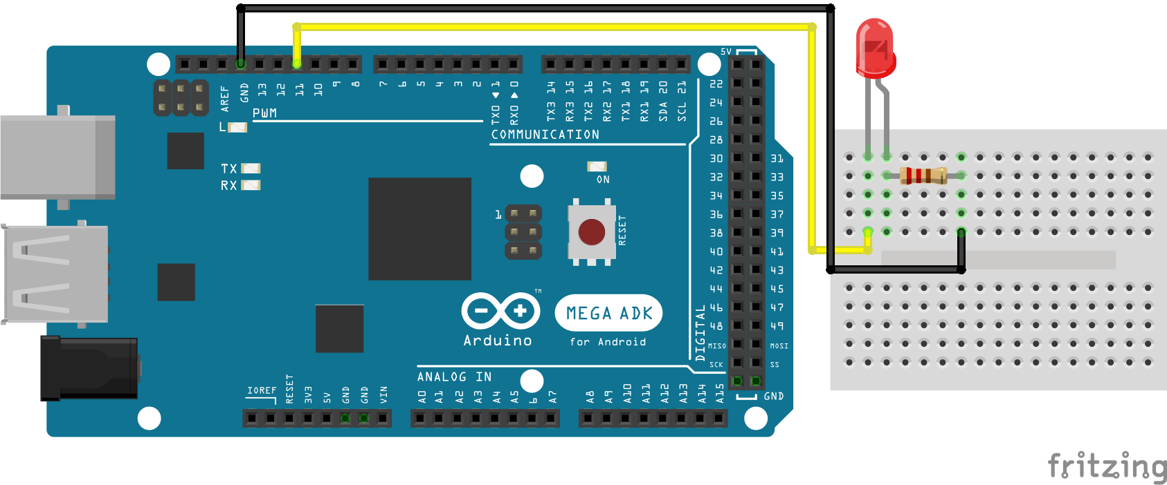
PWM LED Arduino Mega
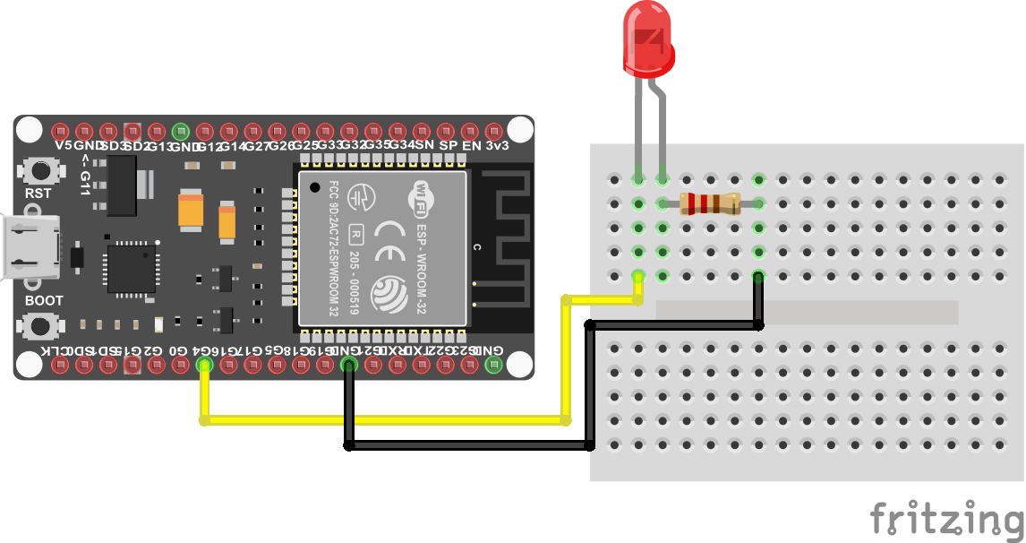
PWM LED ESP32 NodeMCU
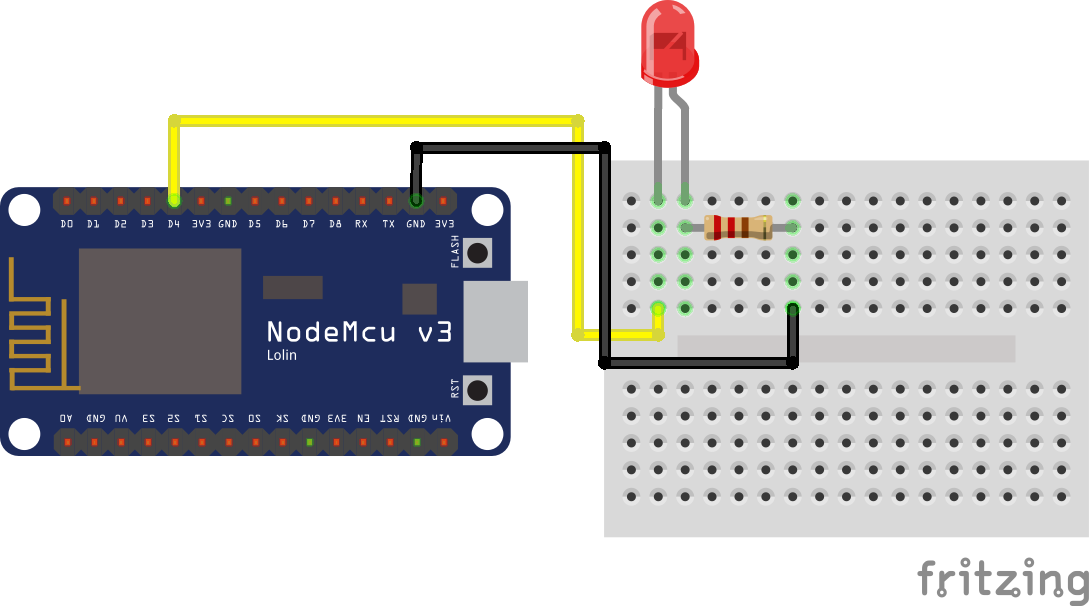
PWM LED ESP8266 NodeMCU
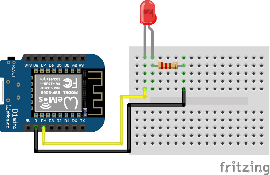
PWM LED ESP8266 WeMos D1 Mini
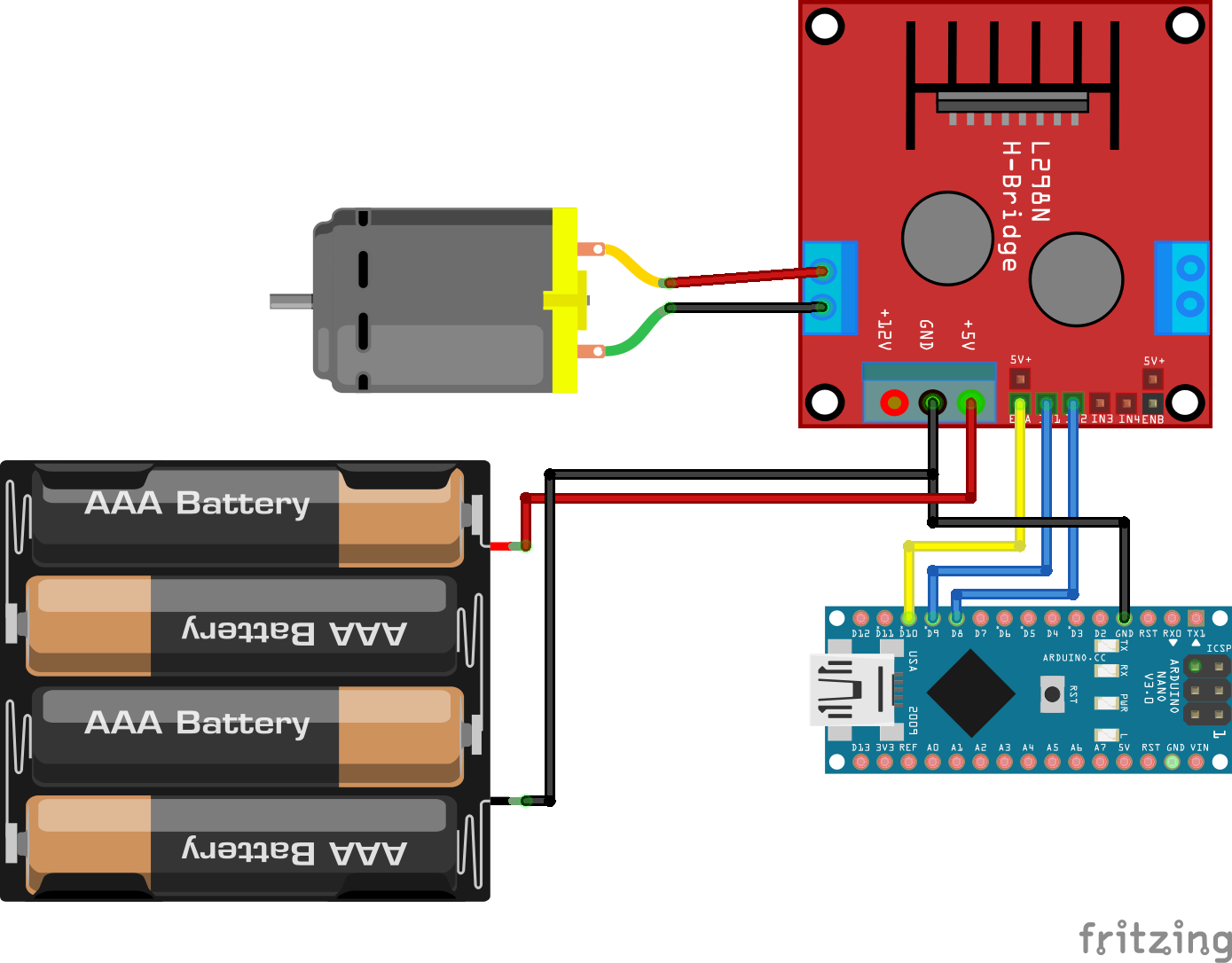
DC Motor L298N Arduino Nano
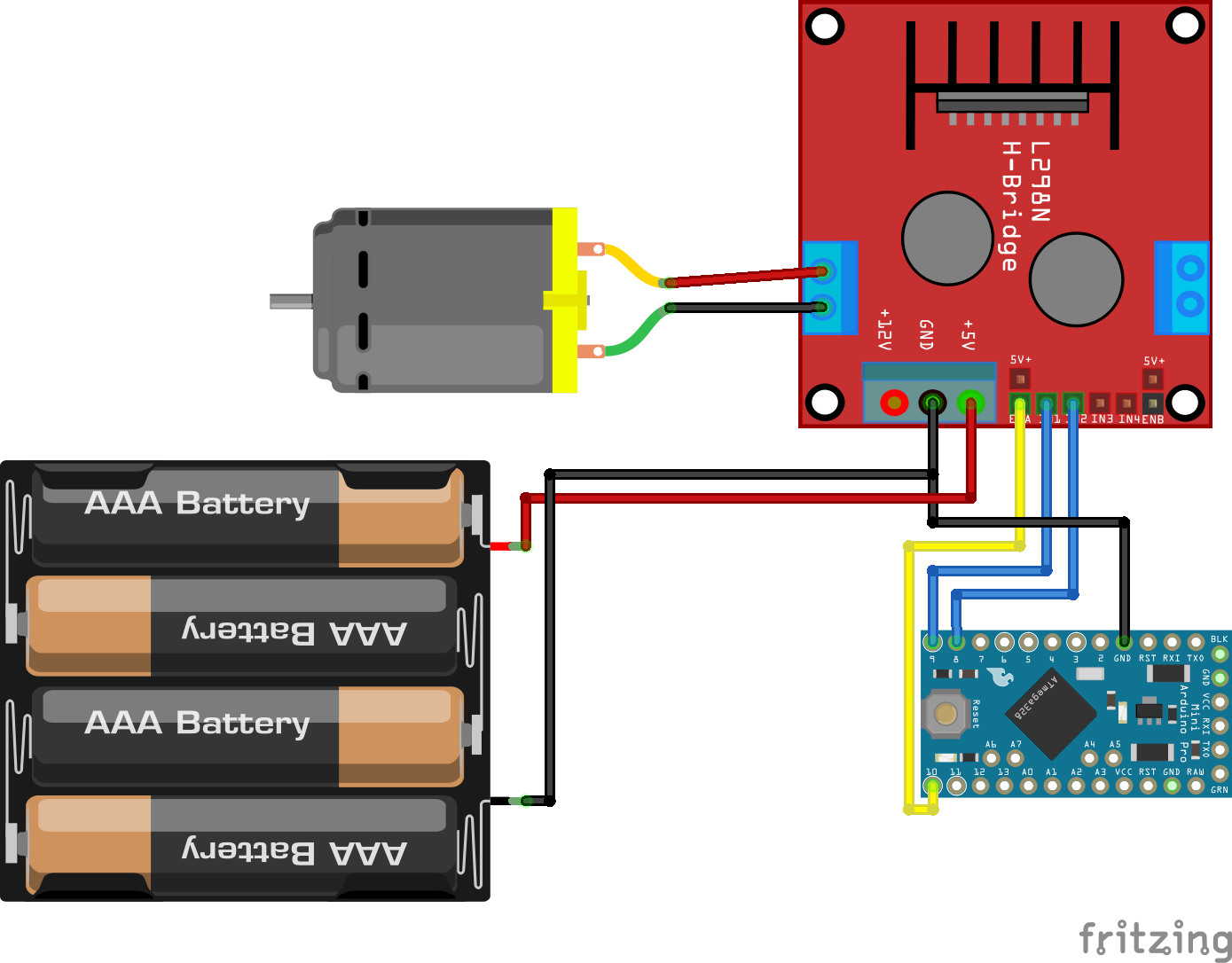
DC Motor L298N Arduino Pro Mini
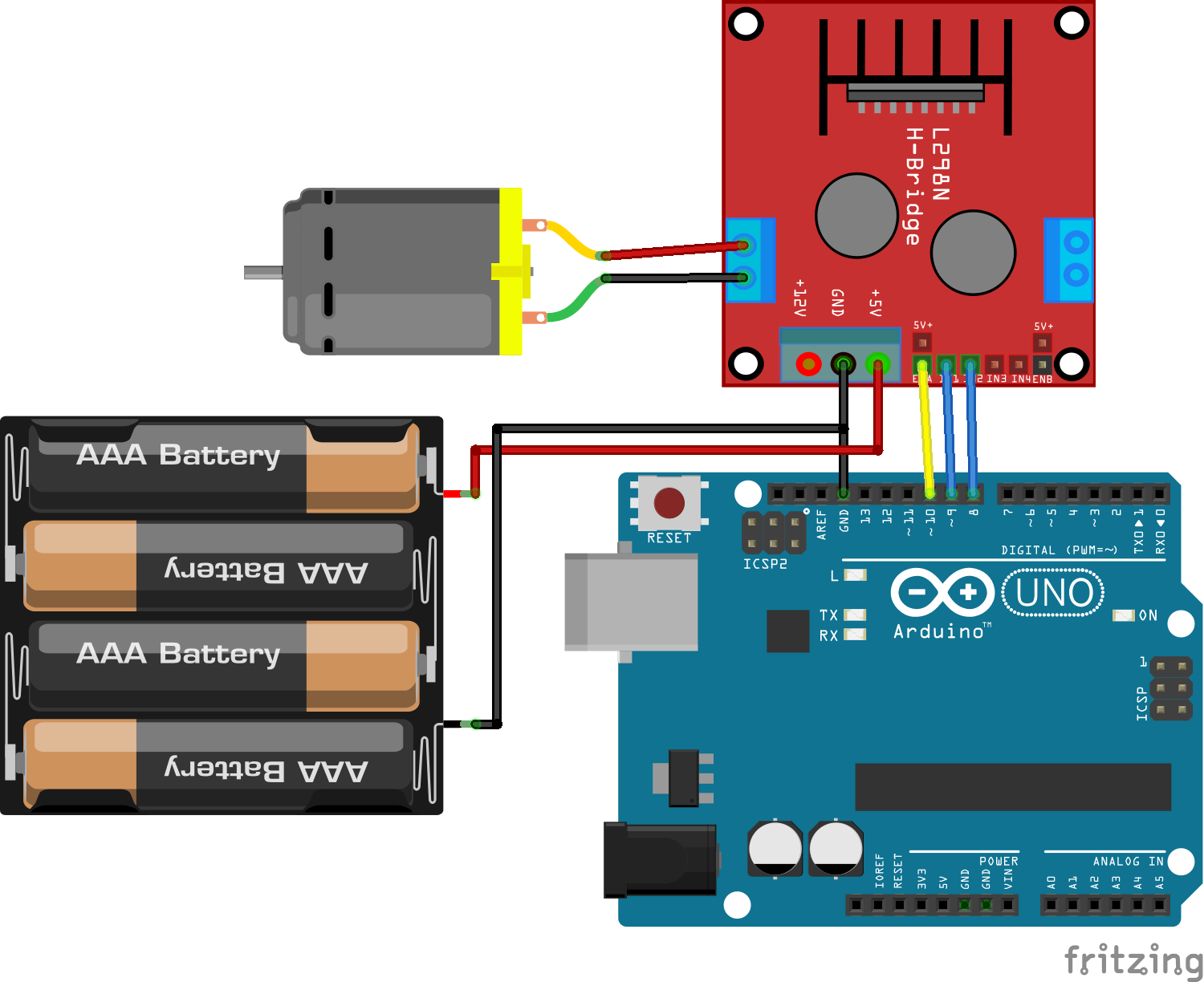
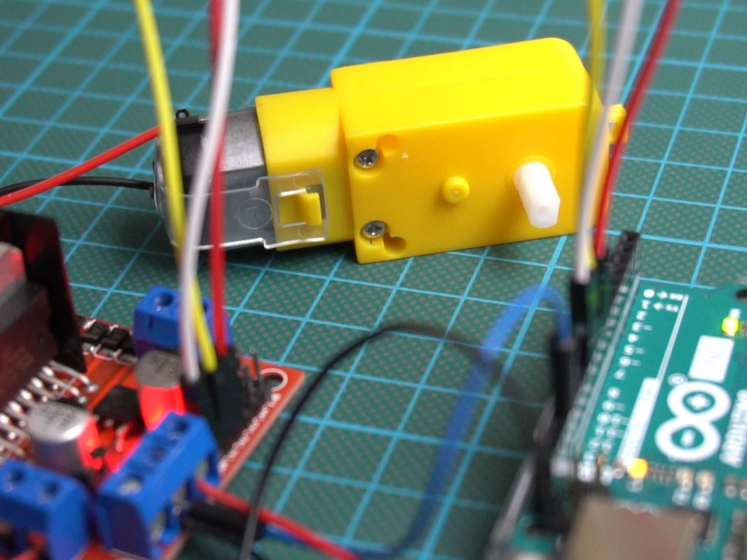
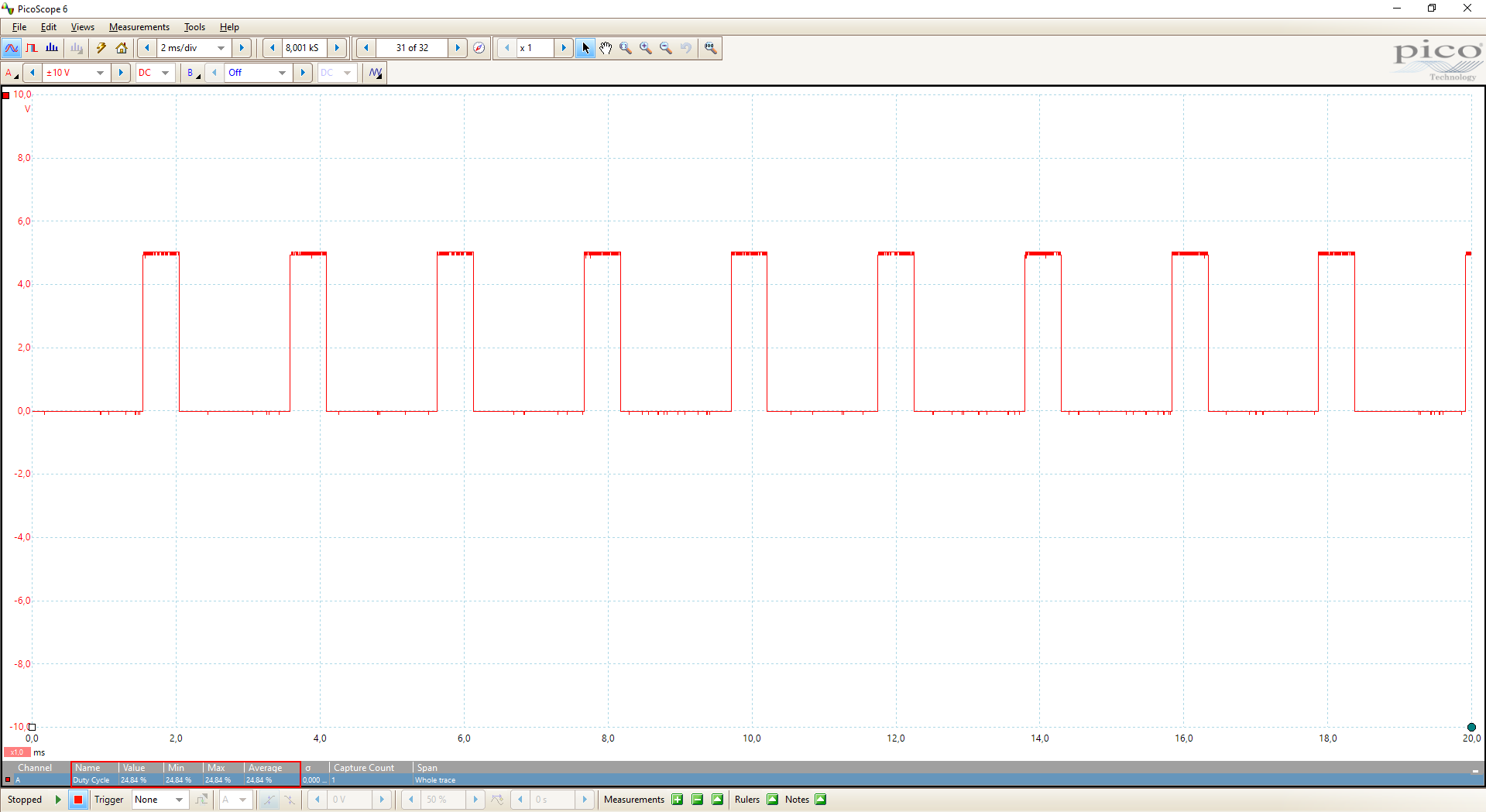
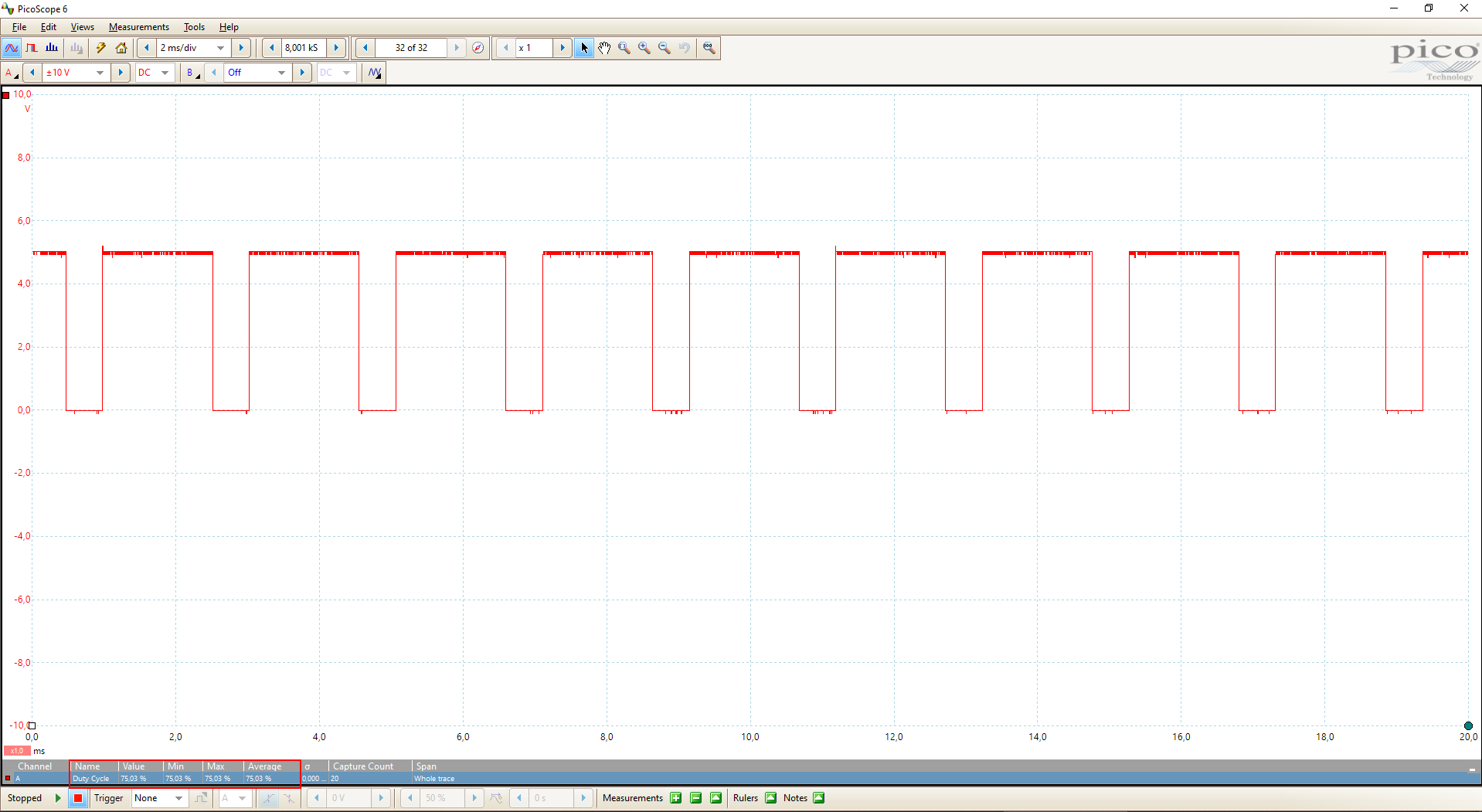
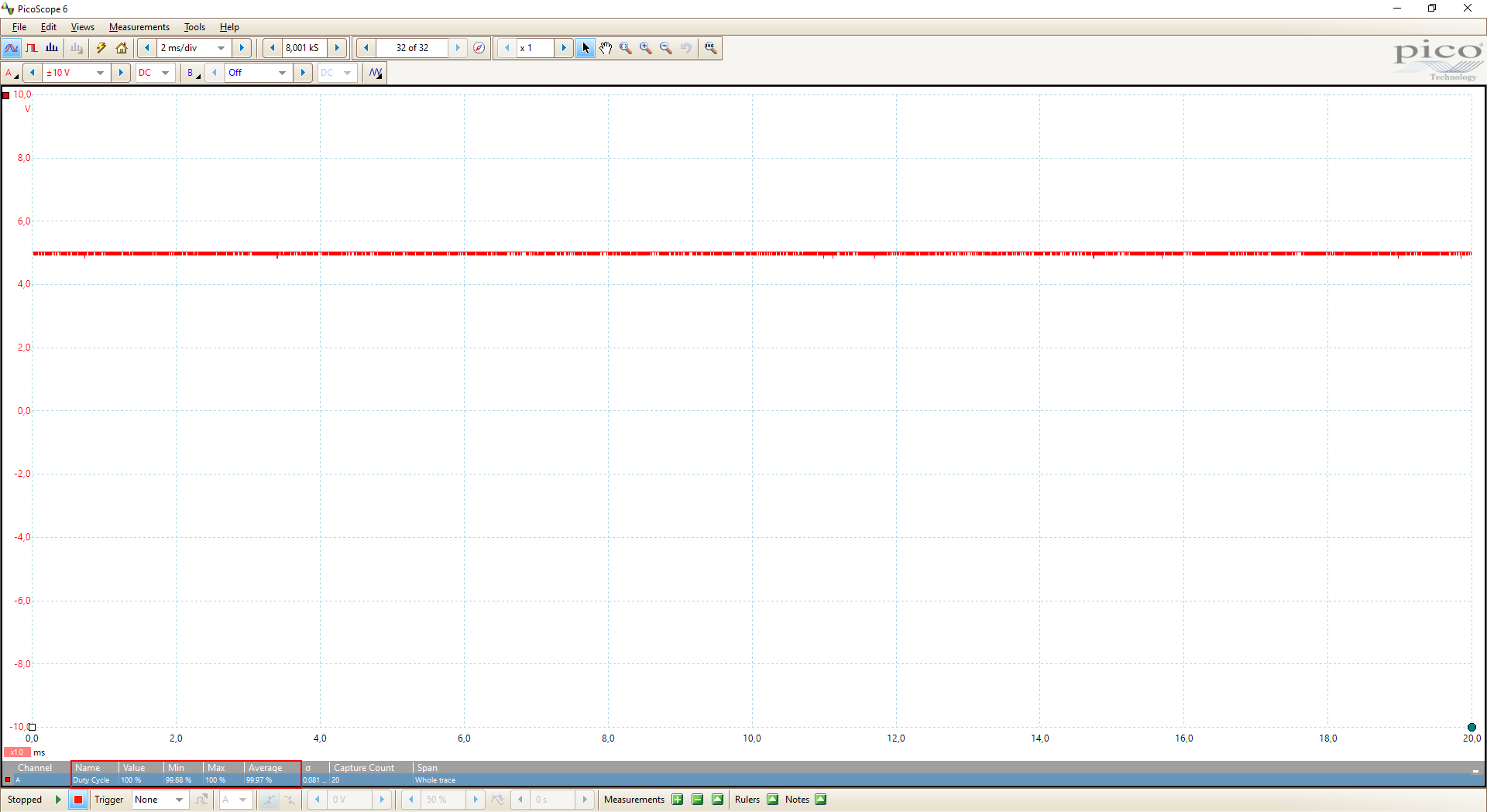
DC Motor L298N Arduino Uno
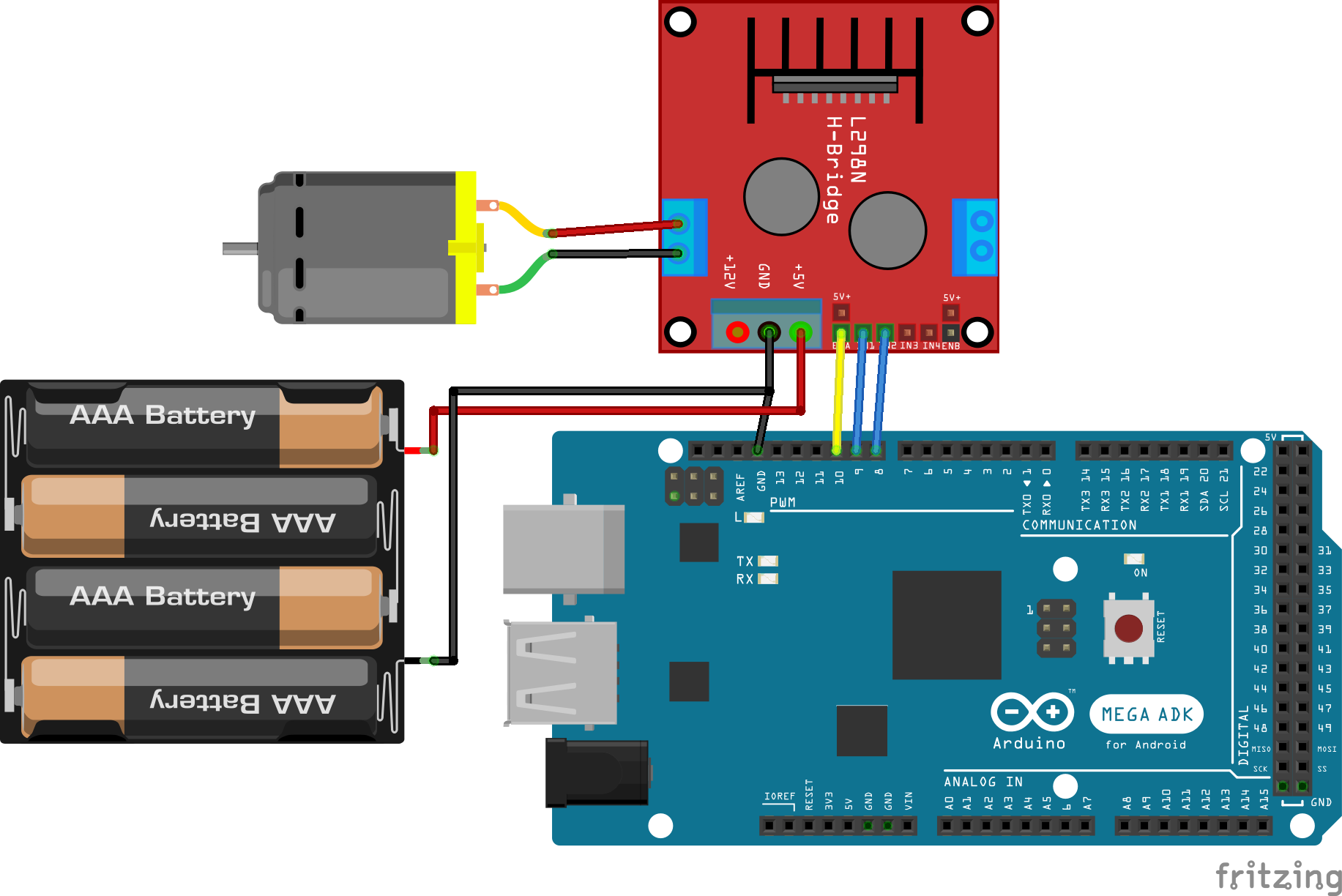
DC Motor L298N Arduino Mega
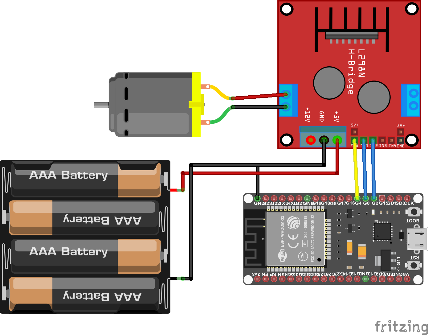
DC Motor L298N ESP32 NodeMCU
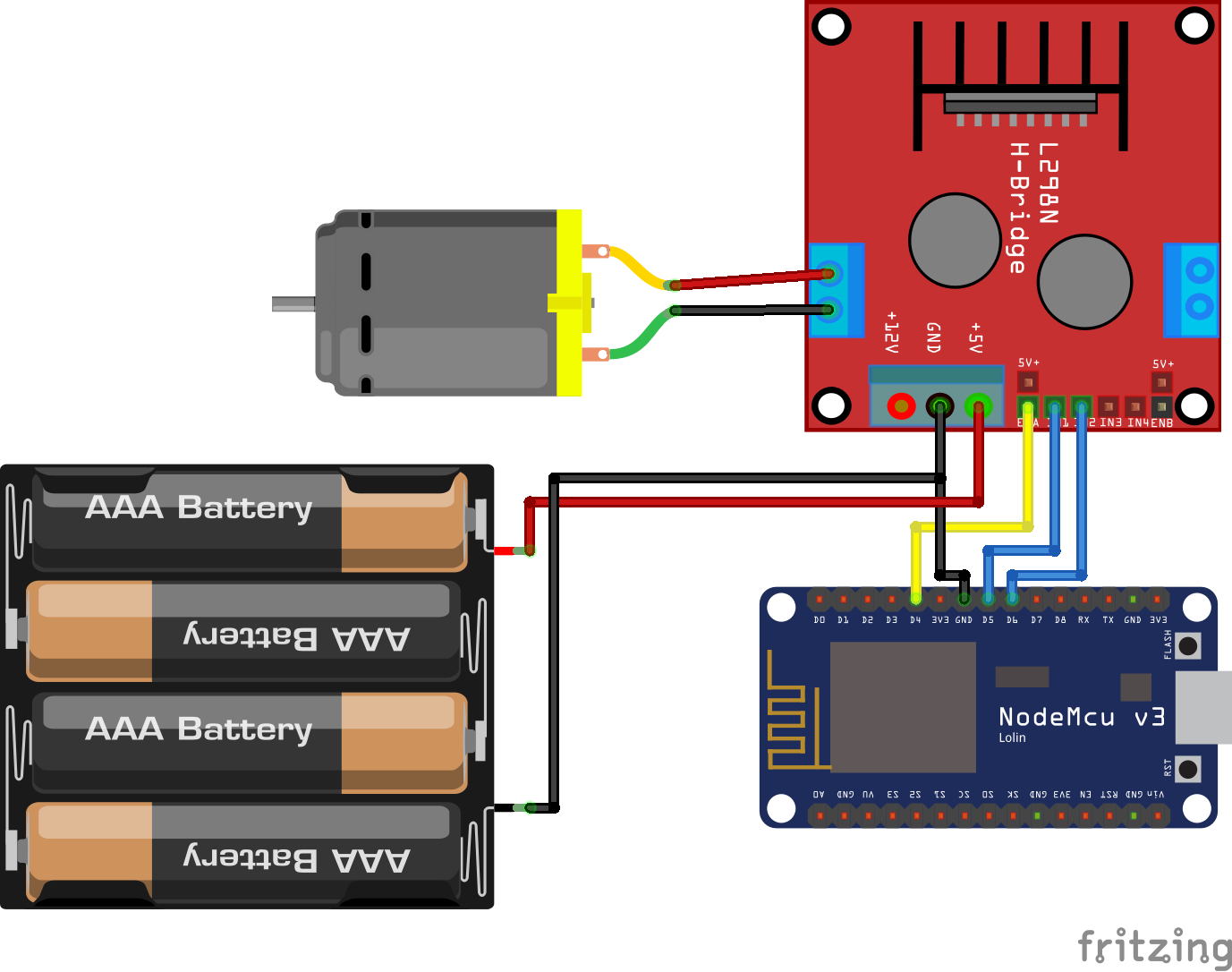
DC Motor L298N ESP8266 NodeMCU
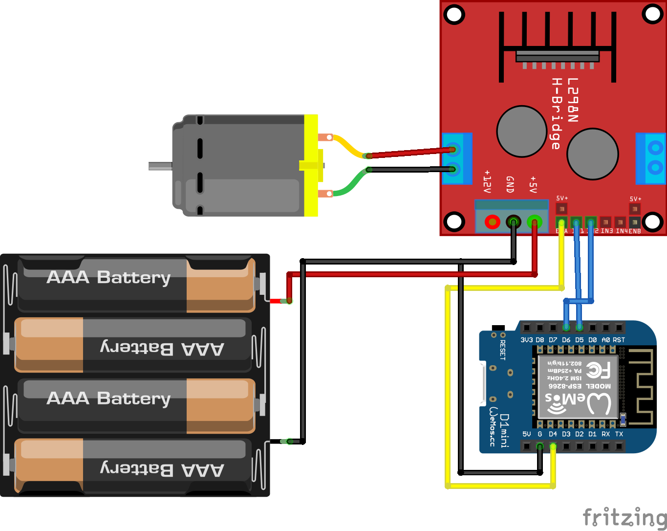
DC Motor L298N ESP8266 WeMos D1 Mini
Leave A Comment