LED Tutorial for Arduino, ESP8266 and ESP32

In this tutorial you learn how to control different LEDs with your Arduino, ESP8266 or ESP32 based micrcontroller.

The different LEDs give you total flexibility in your projects. Staring from a simple one color LED, to indicate the status of a system, to a multi-color LED that is used in gaming room setups.

Light in the dark

Table of Contents

Introduction to LED Tutorial for Arduino, ESP8266 and ESP32

In a lot of my blog posts I use some kind of LED to show what is going on in the sketch, for example when a certain sensor level is reached, a LED turns on. Because there are more lights and different kinds of LED available, we cover all these different devices in this tutorial. With this knowledge you can make your next project more special and awesome.

In this tutorial we often use a Pulse Width Modulation (PWM) signal to change the colors of the LEDs. If you do not know what PWM is, the PWM tutorial teaches you every thing you have to know about PMW. Make sure that you only use PWM pins if you need this functionality. For the ESP8266 and ESP32 based boards, all digital I/O pins are PWM ready. For the Arduino boards you find an overview of the different pinouts in the following articles: Arduino Nano, Arduino Uno, Arduino Mega or you take a look at the Microcontroller Datasheet eBook.

The following table gives you an overview of all components and parts that I use for this tutorial. I get commissions for purchases made through links in this table.

ComponentAmazon LinkAliExpress Link
Arduino Nano AmazonAliExpress
Arduino Pro Mini AmazonAliExpress
Arduino Uno AmazonAliExpress
Arduino Mega AmazonAliExpress
ESP32 ESP-WROOM-32AmazonAliExpress
ESP8266 NodeMCU AmazonAliExpress
ESP8266 WeMos D1 Mini AmazonAliExpress
Two-color LED (KY-011), SMD RGB (KY-009), RGB LED (KY-016), 7 Color Flash LED (KY-034) and Light Blocking (KY-010) are all part of a Sensor Pack AmazonAliExpress

How to Use the Two-color LED (KY-011)

Two-color LED

The Two-color LED (KY-011) module is a bi-color LED because the module emits red and green light. Using PWM you can adjust the amount of each color. Therefore the LED can be completely red or green and all combinations between depending on the inputs for the pins. This defines also the number of pins the KY-011 has:

  1. One pin for the red light input
  2. One pin for the green light input
  3. Ground pin to close the circuit

The operation voltage of the two-color LED KY-011 is between 2V and 2.5V. Therefore we need a resistor in series for the red and green light input to reduce the output voltage on our micocontroller. We will use 330Ω resistors for the Arduino with an operation voltage of 5V and 100Ω resistors for ESP8266 and ESP32 microcontroller with an operation voltage of 3.3V.

Wiring between Two-color LED (KY-011) and Microcontroller

The following table and pictures show the wiring between the Two-color LED KY-011 and the Arduino, ESP8266 or ESP32 microcontroller.

Operating VoltageArduino (Operation Voltage: 5V)ESP8266 and ESP32 (Operation Voltage: 3.3V)
Red2V...2.5VR=330R=100Ω
Green2V...2.5VR=330R=100Ω
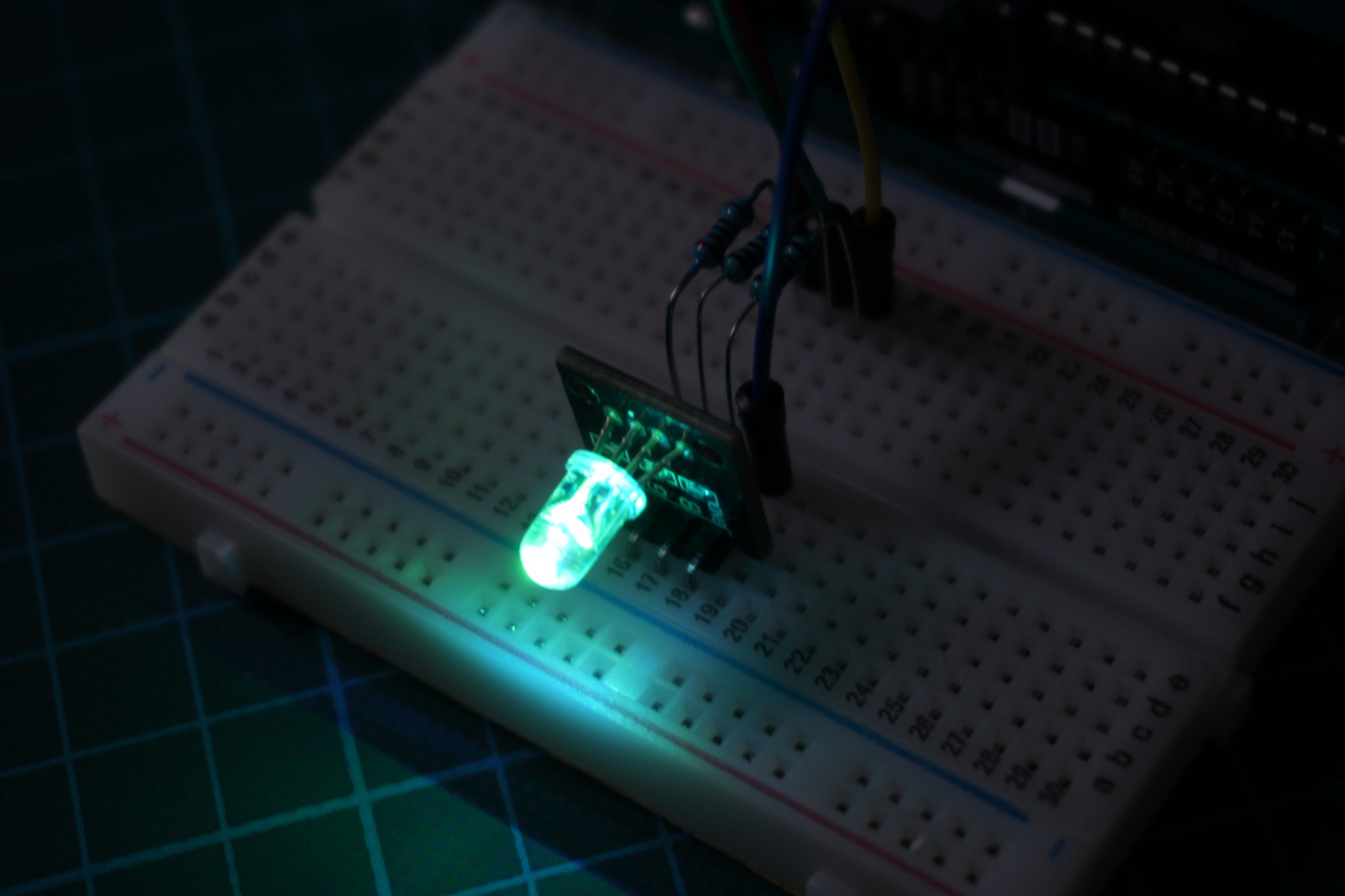
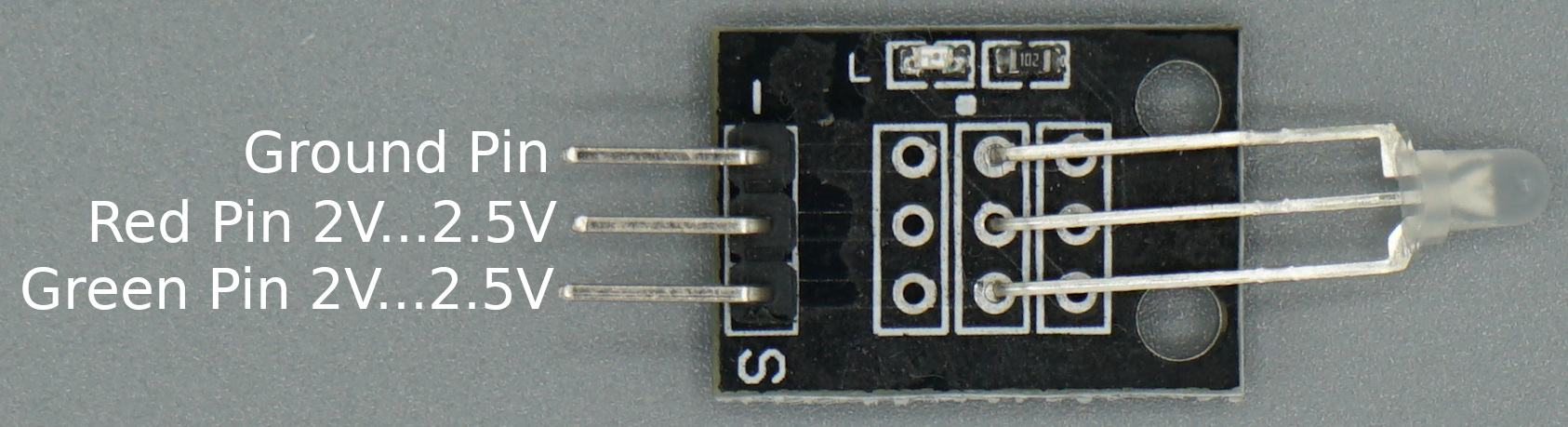
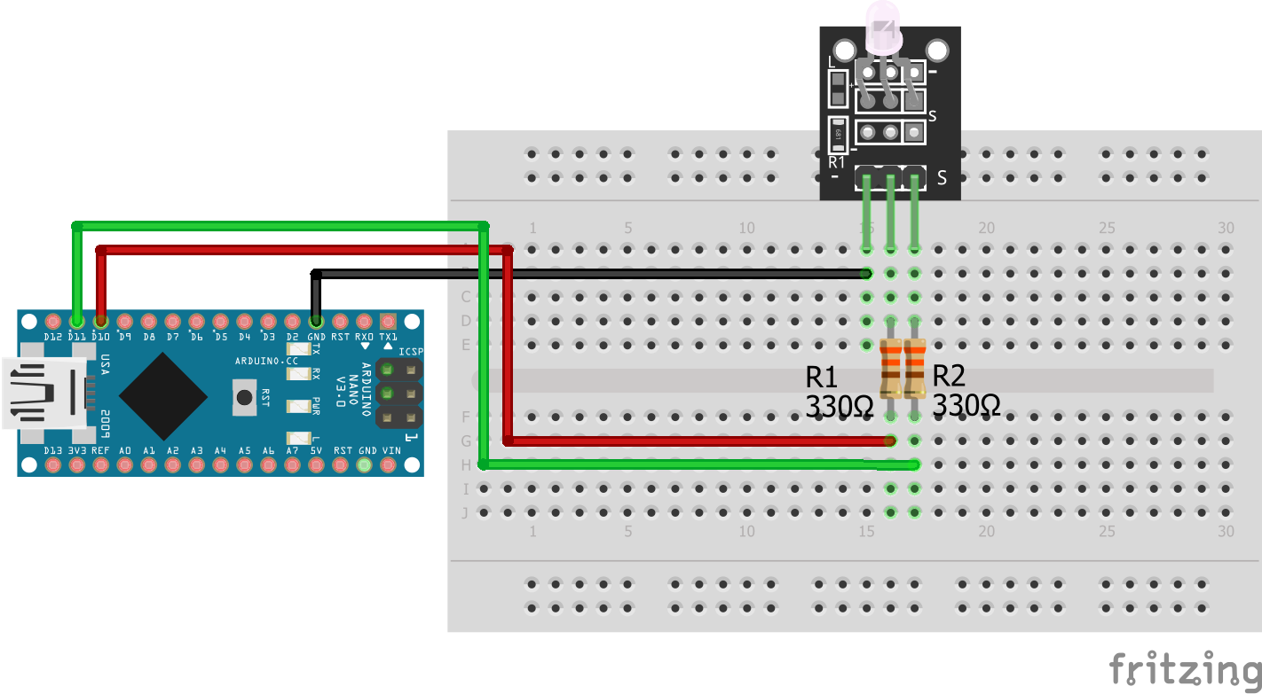
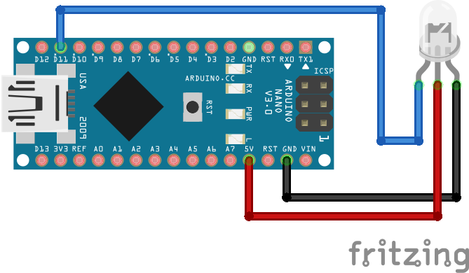
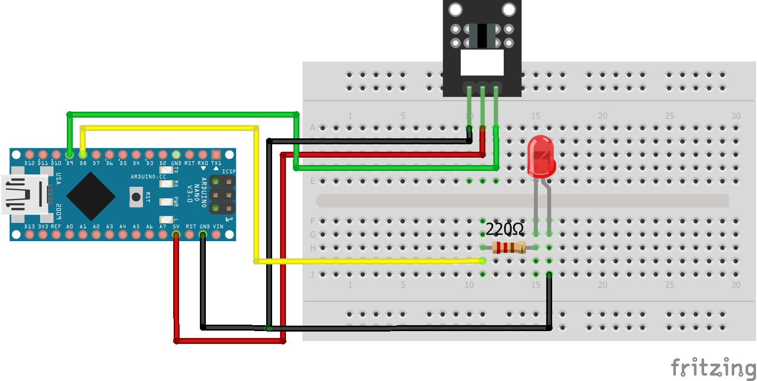
Two-color LED KY-011 Arduino Nano
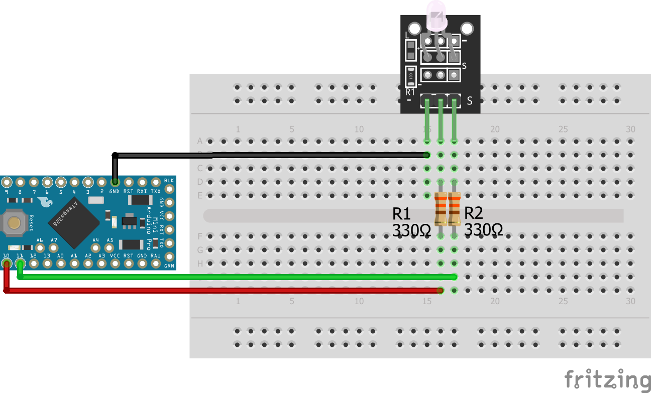
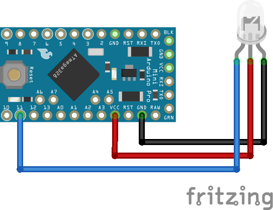
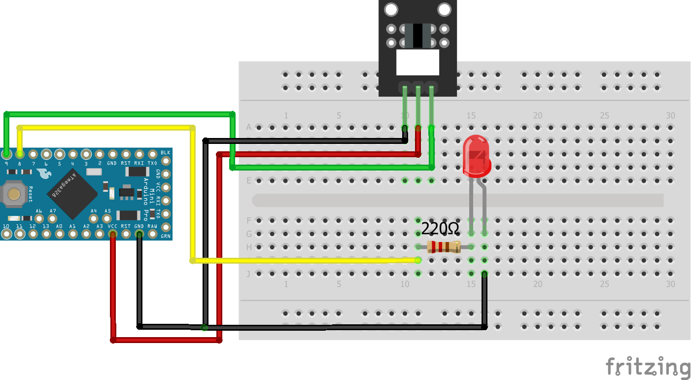
Two-color LED KY-011 Arduino Pro Mini
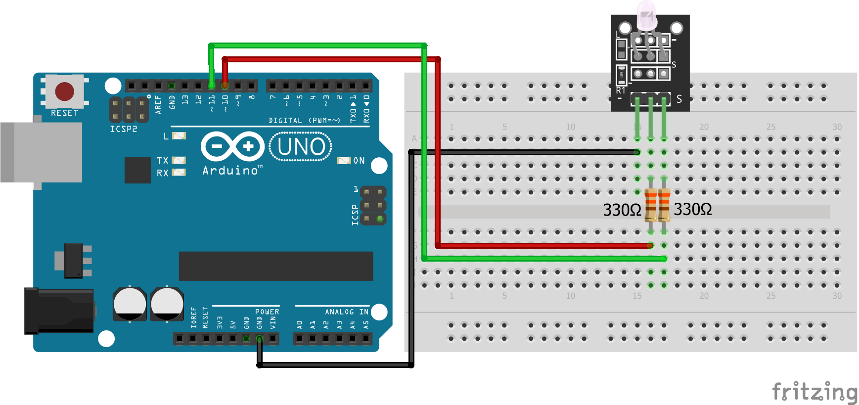
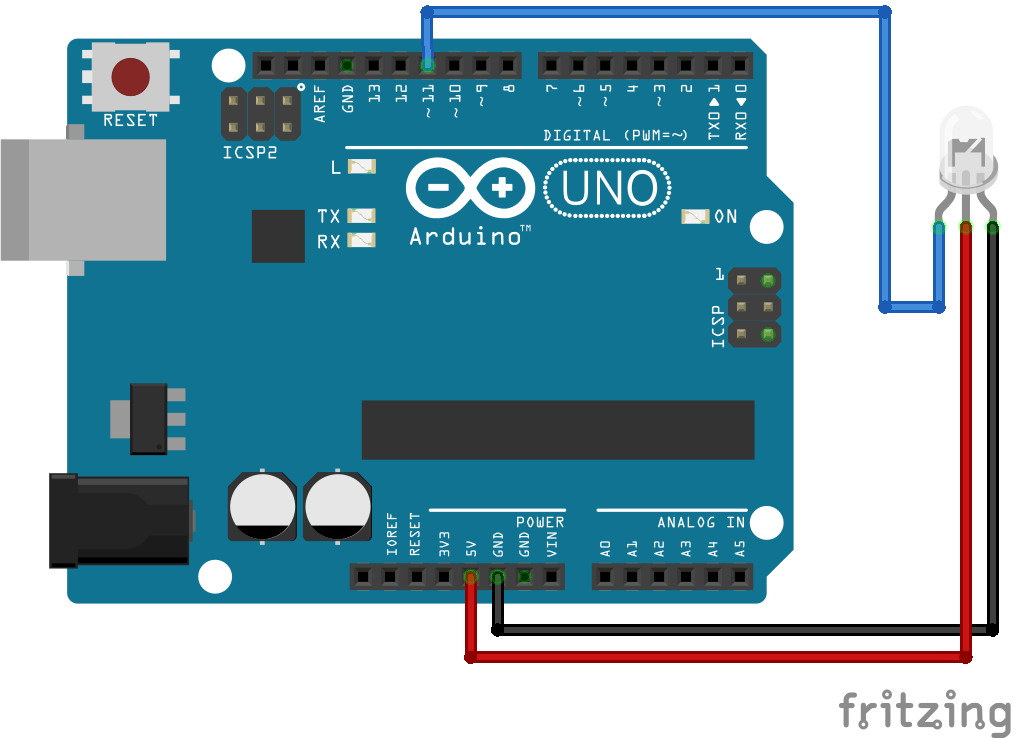
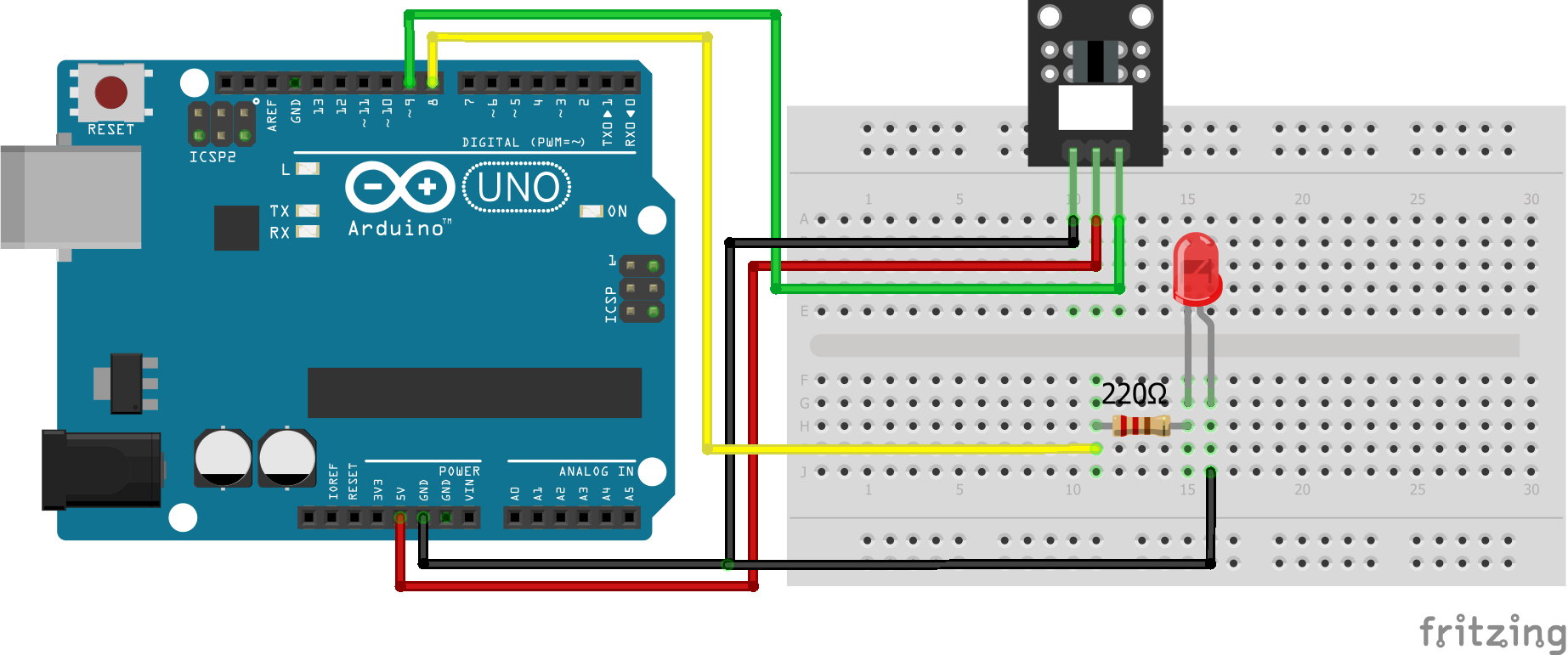
Two-color LED KY-011 Arduino Uno
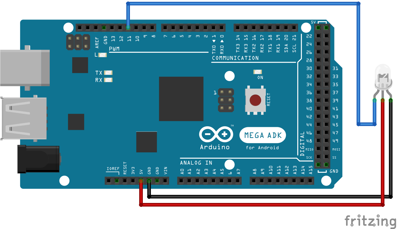
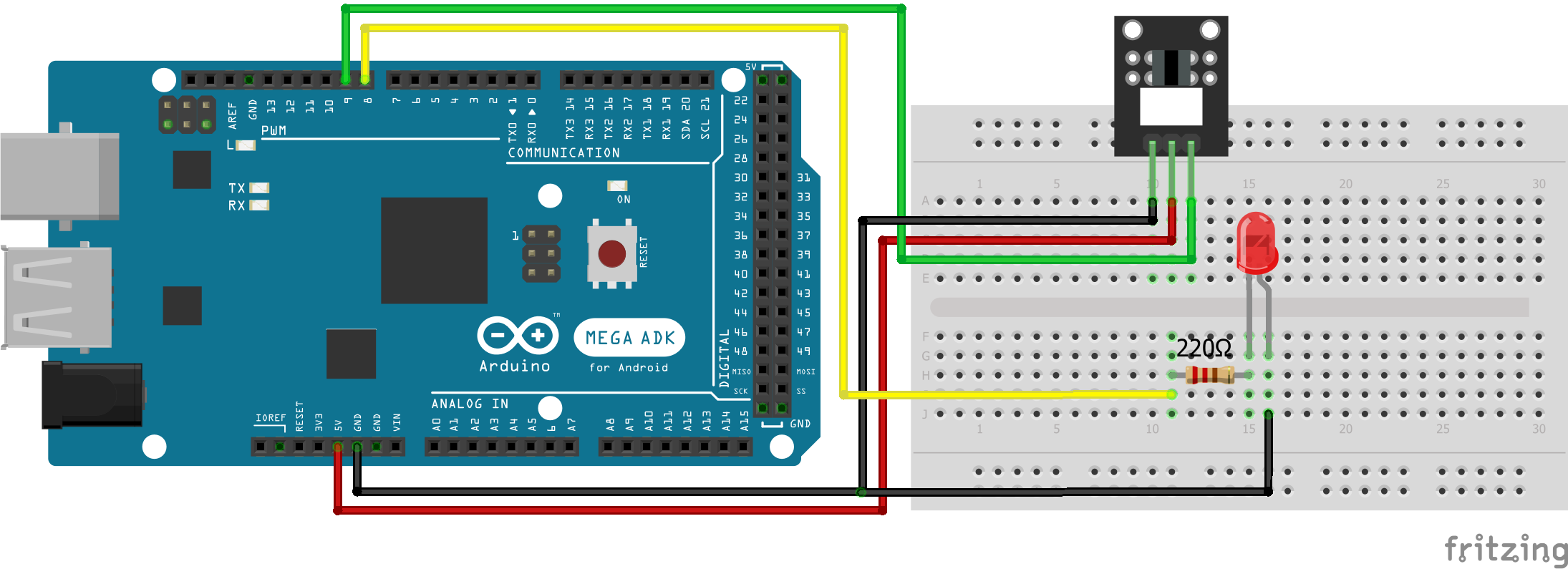
Two-color LED KY-011 Arduino Mega
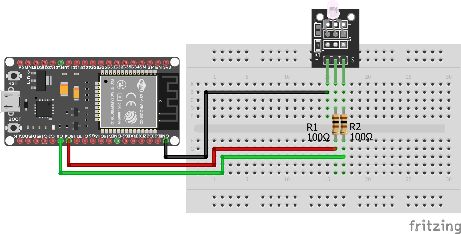
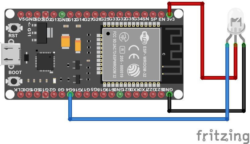
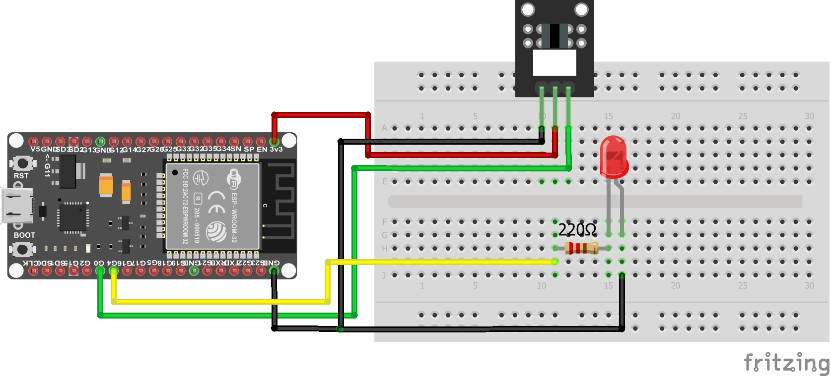
Two-color LED KY-011 ESP32 NodeMCU
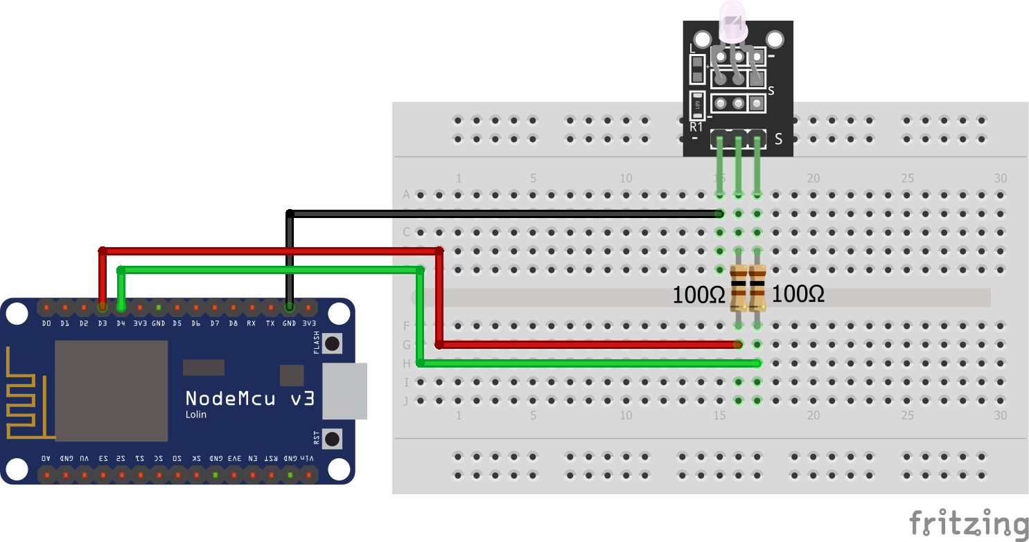
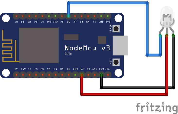
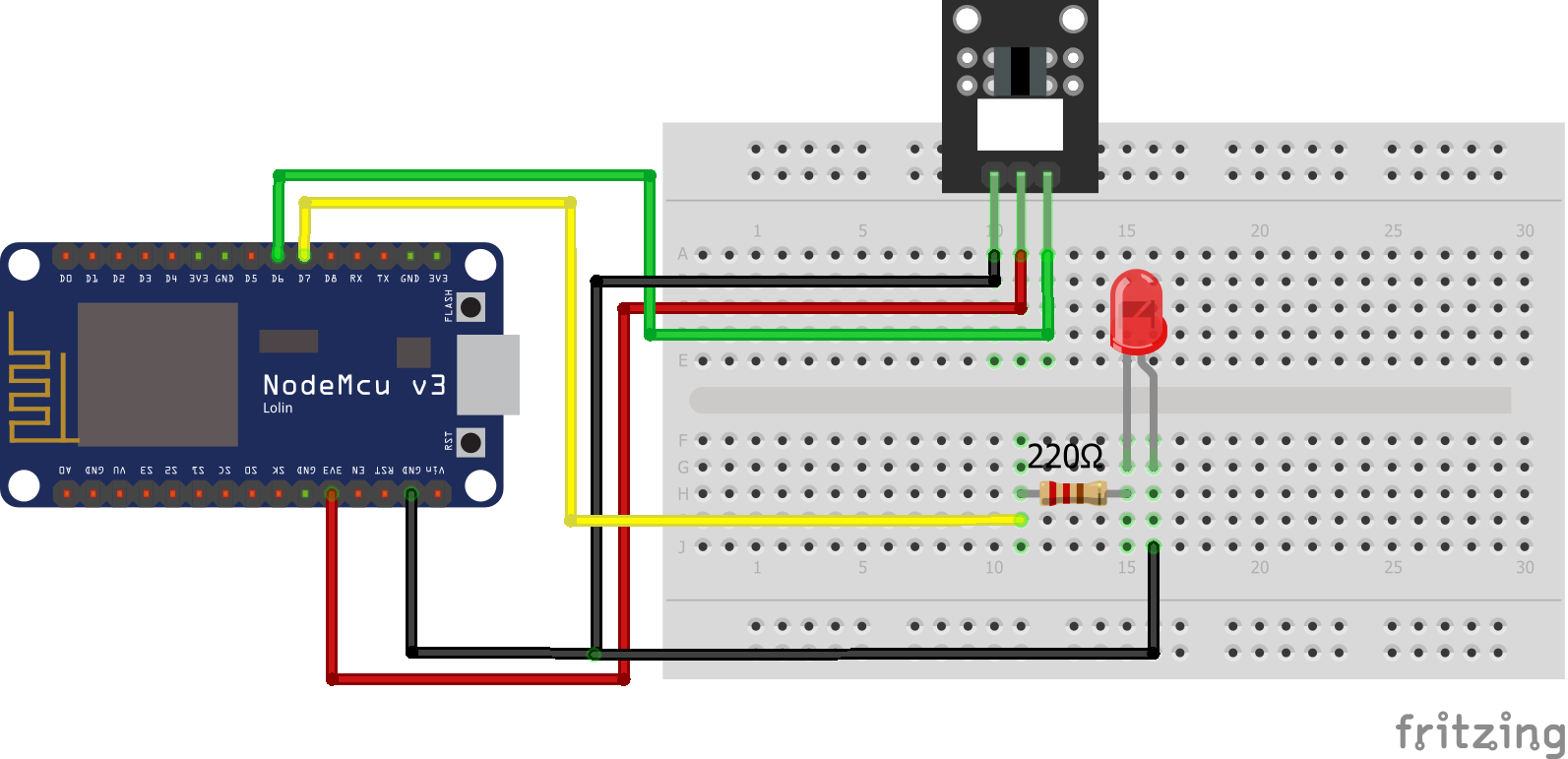
Two-color LED KY-011 ESP8266 NodeMCU
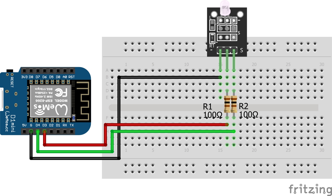
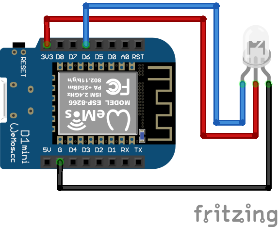
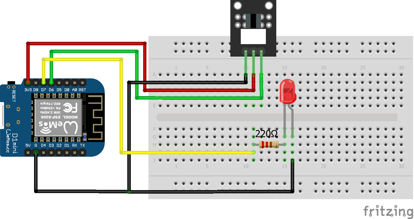
Two-color LED KY-011 ESP8266 WeMos D1 Mini

Microcontroller Datasheet eBook

The 35 pages Microcontroller Datasheet Playbook contains the most useful information of 14 Arduino, ESP8266 and ESP32 microcontroller boards.

Code for Two-color LED (KY-011) to Alternate Two Colors

We want to make a short example sketch for the Two-color LED which alternates the color of the LED between red and green. Therefore we use PWM pins to loop between the green and the red color. It is also possible to only use the full red and green color if you want to make an example for a battery charging project.

  • Battery fully charged: Green LED
  • Battery empty: Red LED
  • Battery is getting charged: Both LED on, so yellow.
// for Arduino microcontroller
int Led_Red = 10;
int Led_Green = 11;

// for ESP8266 microcontroller
//int Led_Red = D3;
//int Led_Green = D4;

// for ESP32 microcontroller
//int Led_Red = 4;
//int Led_Green = 0;


void setup() {
  pinMode(Led_Red, OUTPUT); 
  pinMode(Led_Green, OUTPUT); 
}
void loop() {
   for (int val = 255; val > 0; val--) {
      analogWrite(Led_Green, val);
      analogWrite(Led_Red, 255-val);
      delay(15);
   }
   for (int val = 0; val < 255; val++) {
      analogWrite(Led_Green, val);
      analogWrite(Led_Red, 255-val);
      delay(15);
   }
}

At the beginning of the script we have to define the connection pins between the two color LED and the Arduino, ESP8266 or ESP32 microcontroller. Therefore you see that the connection of the red and green pin is defined three times. Because you only need the lines for your microcontroller, you can delete the other lines for the connection or comment the lines, like I did it for the ESP8266 and ESP32.

In the setup function we define that the pins for the red and green LED should be outputs because we want to output an PWM signal from the microcontroller to change the color of the KY-011.

The loop function contains two for loops. In each for loop we start by setting one color (red or green) to the full brightness by the PWM signal (val = 255) and the other color the the lowest brightness (val = 0). Then we decrease the brightness of the main color and increase the brightness of the other color until the ratio is totally inverted. For example:

  • first iteration of the first for loop: val = 255
    • green LED has a val of 255
    • red LED has a val of 0
    • therefore the LED is green
  • 127 / mittle iteration of the first for loop: val = 128
    • green LED has a val of 128
    • red LED has a val of 127
    • therefore the LED is yellow
  • last iteration of the first for loop: val = 1
    • green LED has a val of 1
    • red LED has a val of 254
    • therefore the LED is red

In the second for loop we invert the whole logic and the color of the LED goes back from red to green.

The following video shows the two color LED in action, changing the color from green over yellow to red and back.

YouTube

By loading the video, you agree to YouTube's privacy policy.
Learn more

Load video

How to Use the SMD RGB (KY-009)

SMD RGB

The SMD RGB (KY-009) is like the Two-color LED (KY-011) but is able to emit red, green and blue instead of only red and green. Therefor all RGB full colors can be emitted by the SMD RGB module due to the mix of red, green and blue. Like the Two-color LED (KY-011) also the SMD RGB (KY-009) use PWM to adjust the amount of each color. The module has 4 pins to connect to your microcontroller. The following pictures shows you how to connect the KY-011 to your Arduino, ESP8266 or ESP32 based microcontroller.

Wiring between SMD RGB (KY-009) and Microcontroller

Important: The LED SMD Module consists of a 5050 SMD LED which has to prevent against burnout with limiting resistors. The following table shows you the operating voltage and the used resistors to prevent the burnout.

Operating VoltageArduino (Operation Voltage: 5V)ESP8266 and ESP32 (Operation Voltage: 3.3V)
Red1.8V...2.4VR=220ΩR=100Ω
Green2.8V...3.6VR=100ΩNo resistor needed
Blue2.8V...3.6VR=100ΩNo resistor needed
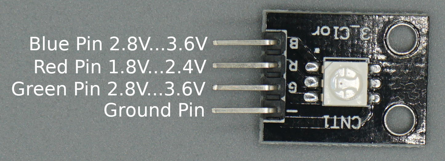
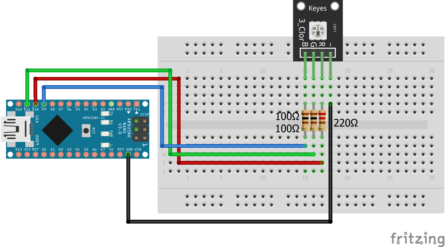
SMD RGB KY-009 Arduino Nano
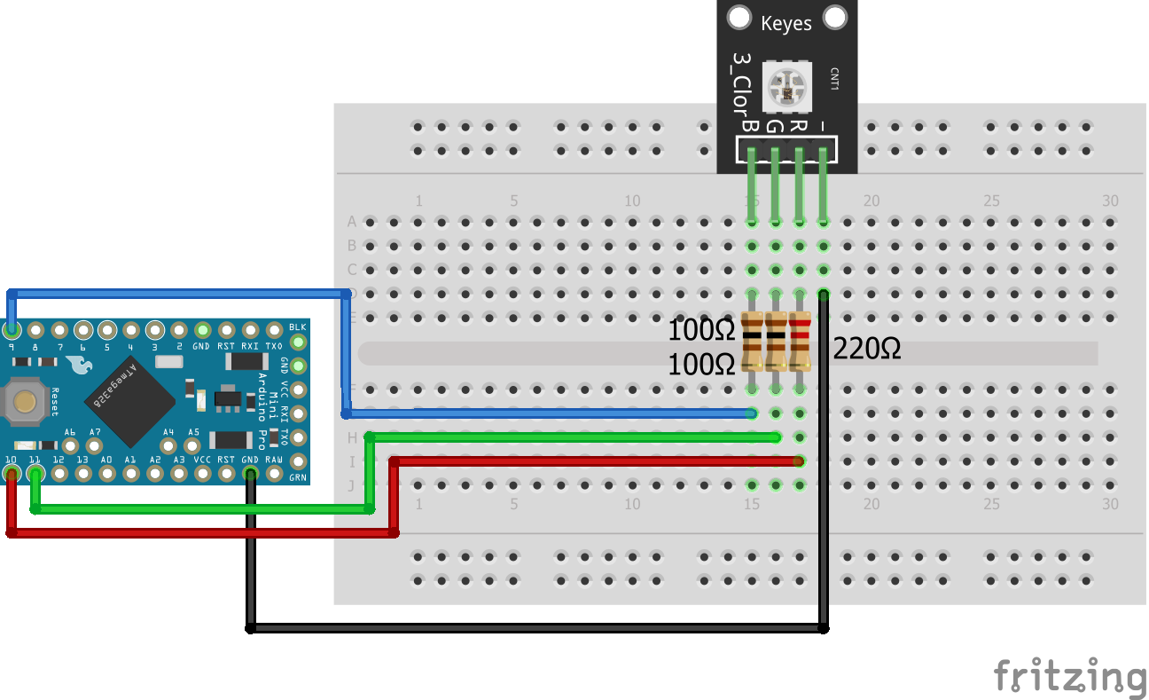
SMD RGB KY-009 Arduino Pro Mini
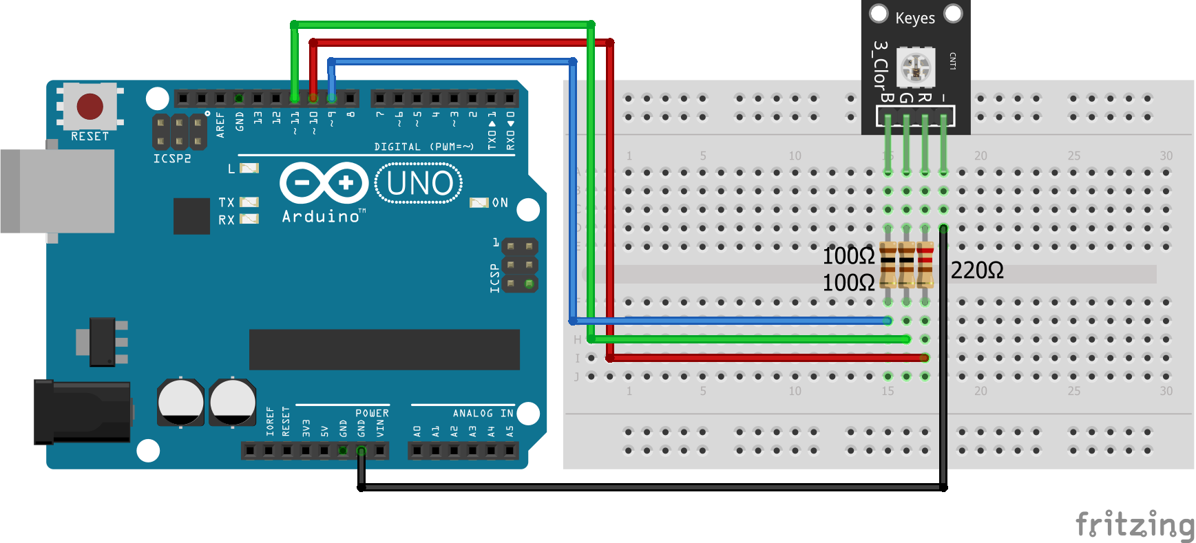
SMD RGB KY-009 Arduino Uno
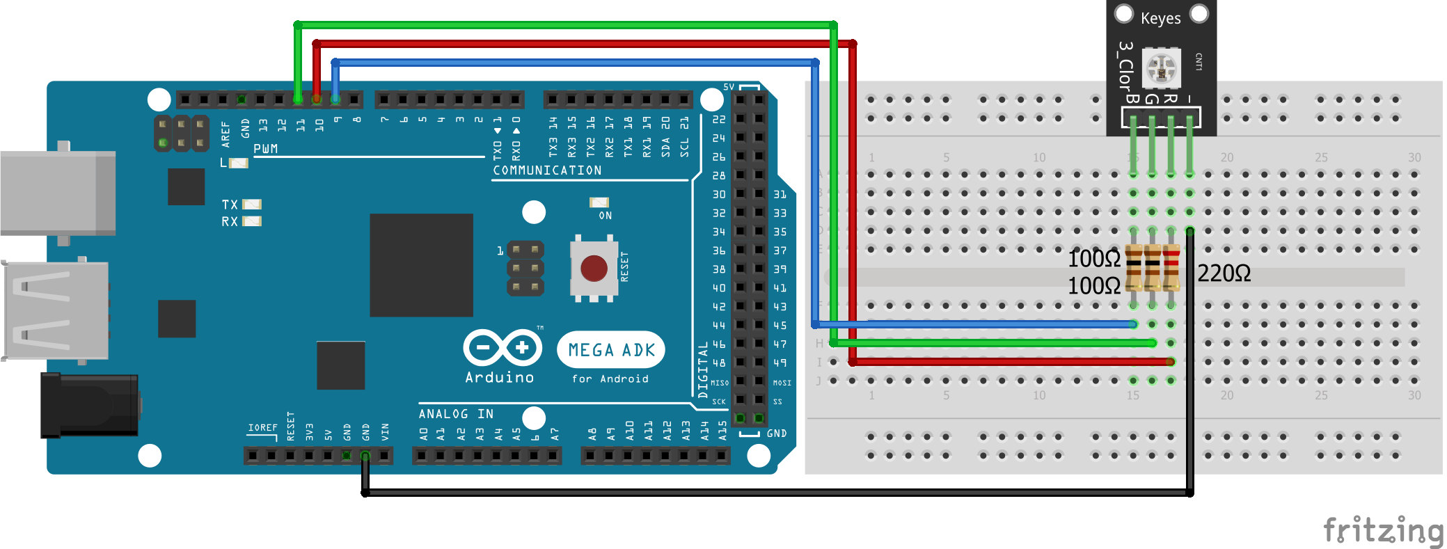
SMD RGB KY-009 Arduino Mega
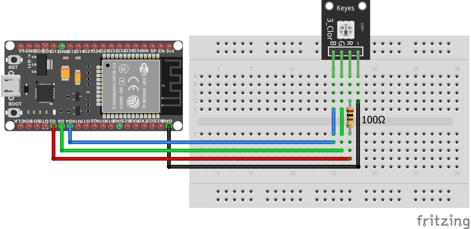
SMD RGB KY-009 ESP32 NodeMCU
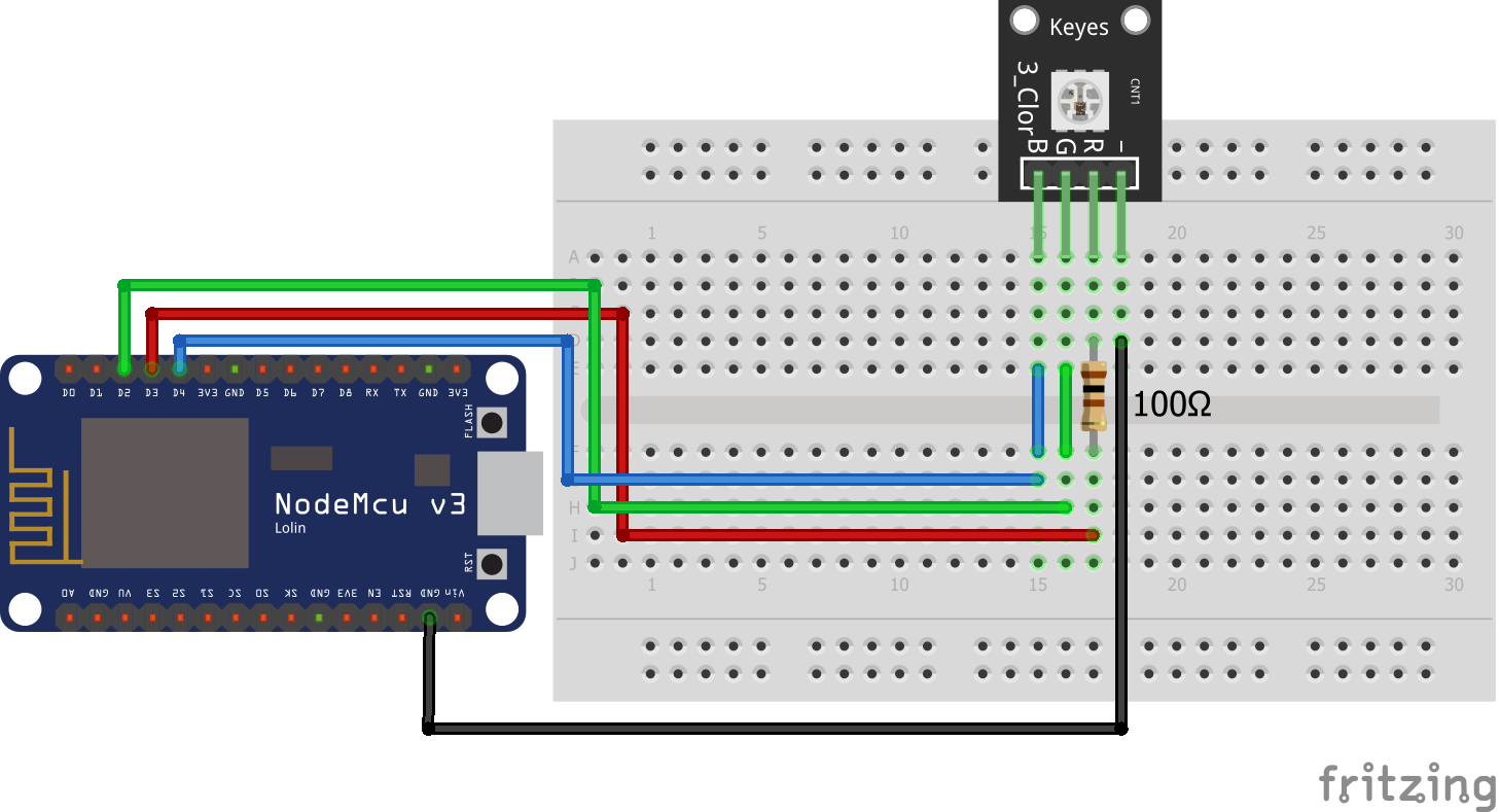
SMD RGB KY-009 ESP8266 NodeMCU
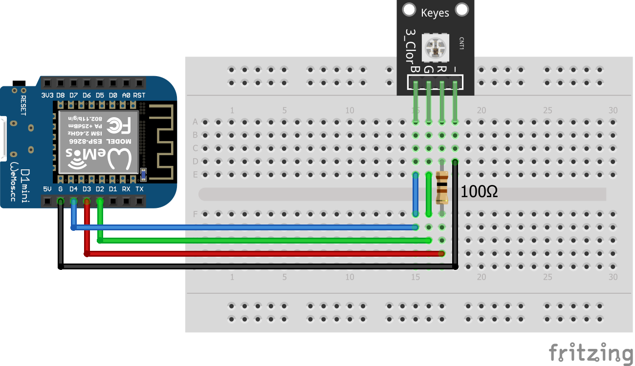
SMD RGB KY-009 ESP8266 WeMos D1 Mini

Code for SMD RGB (KY-009) to Cycle Through Various Colors

We want to make a short example sketch for the SMD RGB (KY-009) which cycle through various colors by changing the PWM value on each of the three primary colors. Based on this example script you can create unlimited variations. For example if you do not want to change one RGB color, you can define a static PWM value for this color outside the for loops.

// for Arduino microcontroller
int Led_Red = 10;
int Led_Green = 11;
int Led_Blue = 9;

// for ESP8266 microcontroller
//int Led_Red = D3;
//int Led_Green = D2;
//int Led_Blue = D4;

// for ESP32 microcontroller
//int Led_Red = 2;
//int Led_Green = 0;
//int Led_Blue = 4;
 

void setup() {
  pinMode(Led_Red, OUTPUT); 
  pinMode(Led_Green, OUTPUT); 
  pinMode(Led_Blue, OUTPUT); 
}
void loop() {
   for(int val = 255; val> 0; val--) {
      analogWrite (Led_Red, val);
      analogWrite (Led_Blue, 255-val);
      analogWrite (Led_Green, 128-val);
      delay (15);
   }

   for(int val = 0; val <255; val++) {
      analogWrite (Led_Red, val);
      analogWrite (Led_Blue, 255-val);
      analogWrite (Led_Green, 128-val);
      delay (15);
   }
}

You know most of the program script from the first example. Basically the script is like the first one, but instead of two LEDs, you to control tree LEDs.

Therefore we have to define the tree pins that connect the SMD RGB LED to the Arduino, ESP8266 or ESP32 microcontroller and define the blue LED as output in the setup function.

In the loop function, we mix the brightness of the different LEDs by changing the PWM values. This results in different colors.

The following video shows the result of the sketch. The SMD RGB LED is changing to different colors.

YouTube

By loading the video, you agree to YouTube's privacy policy.
Learn more

Load video

How to Use the RGB LED (KY-016)

RGB LED

The RGB LED module is the same like the SMD RGB (KY-009). It only has a slightly different operating voltage, see the table below. But because the operating voltage differs only a little we use the same resistors to prevent the burnout of the module.

Operating VoltageArduino (Operation Voltage: 5V)ESP8266 and ESP32 (Operation Voltage: 3.3V)
Red1.8V...2.1VR=220ΩR=100Ω
Green3V...3.2VR=100ΩNo resistor needed
Blue3V...3.2VR=100ΩNo resistor needed

Wiring between RGB LED (KY-016) and Microcontroller

The following pictures show the wiring between the RGB LED (KY-016) and the different Arduino, ESP8266 or ESP32 microcontroller boards.

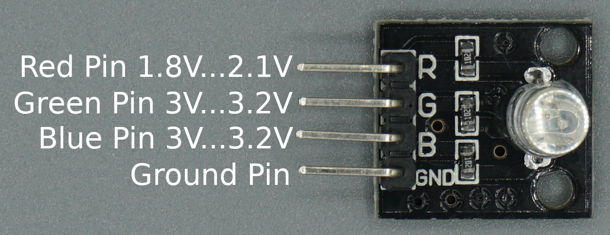
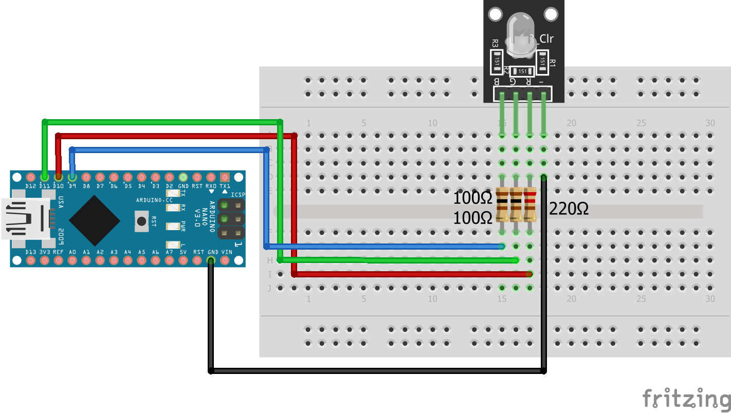
RGB LED KY-016 Arduino Nano
RGB LED KY-016 Arduino Pro Mini
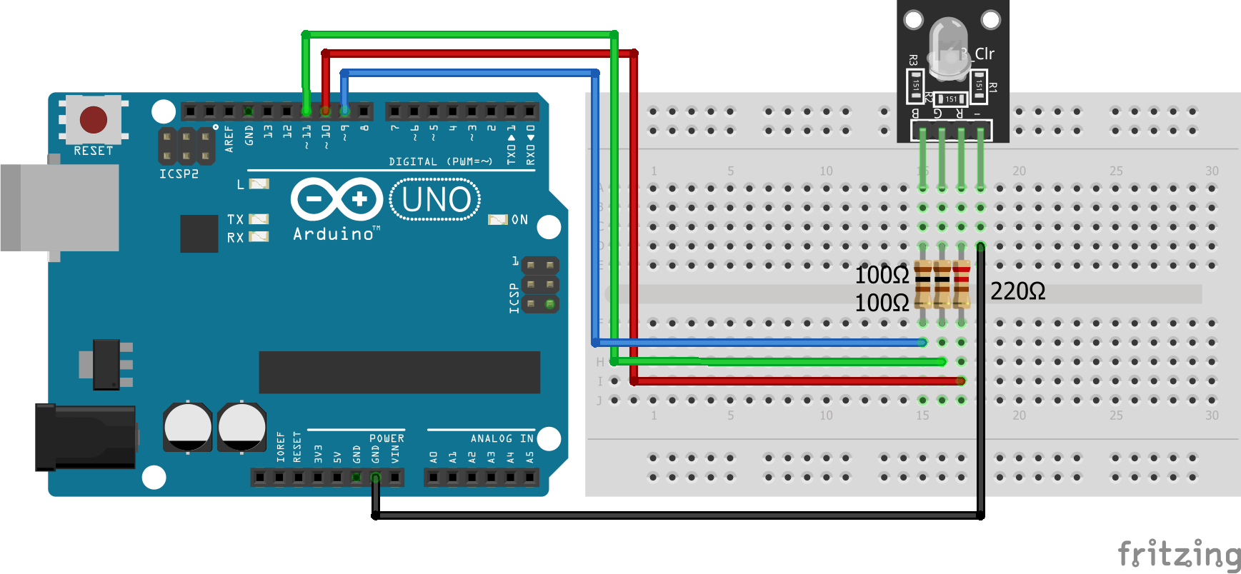
RGB LED KY-016 Arduino Uno
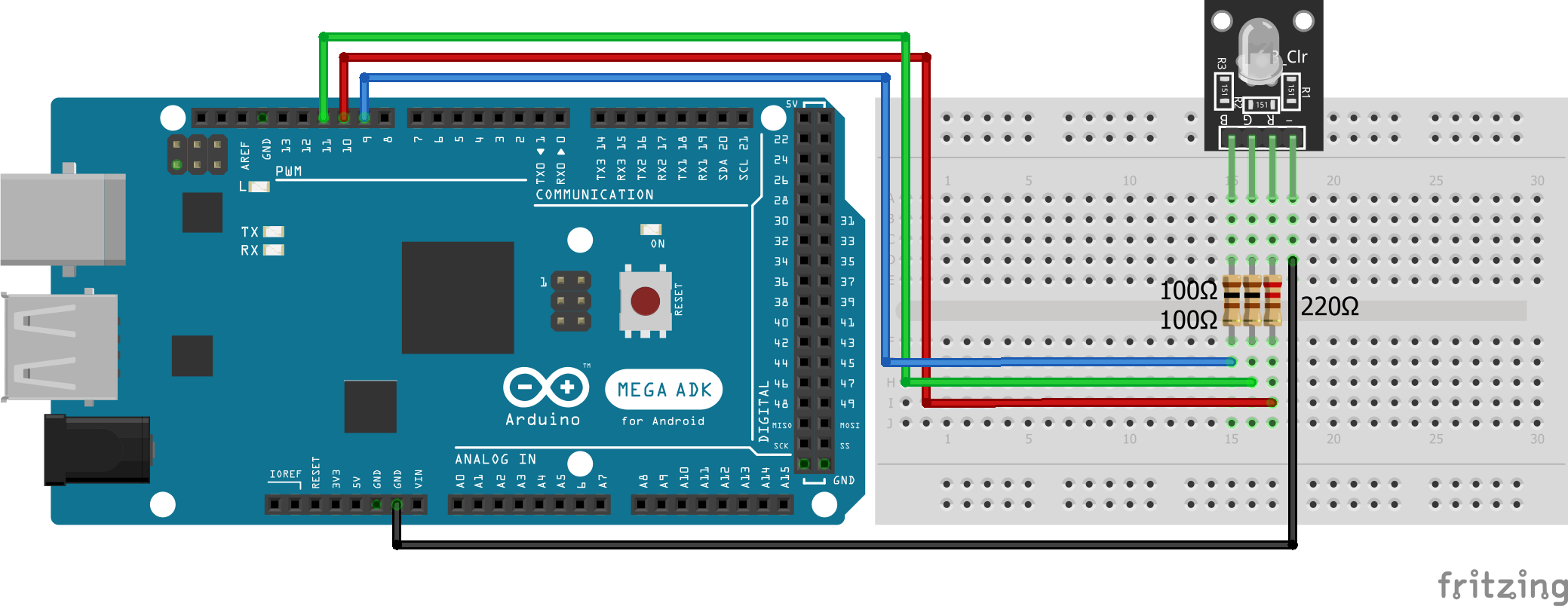
RGB LED KY-016 Arduino Mega
RGB LED KY-016 ESP32 NodeMCU
RGB LED KY-016 ESP8266 NodeMCU
RGB LED KY-016 ESP8266 WeMos D1 Mini

Code for RGB LED (KY-016) to Cycle Through Various Colors

For the RGB LED we use the same program code like for the SMD RGB (KY-009) which cycle through various colors by changing the PWM value on each of the three primary colors.

// for Arduino microcontroller
int Led_Red = 10;
int Led_Green = 11;
int Led_Blue = 9;

// for ESP8266 microcontroller
//int Led_Red = D3;
//int Led_Green = D2;
//int Led_Blue = D4;

// for ESP32 microcontroller
//int Led_Red = 2;
//int Led_Green = 0;
//int Led_Blue = 4;
 

void setup() {
  pinMode(Led_Red, OUTPUT); 
  pinMode(Led_Green, OUTPUT); 
  pinMode(Led_Blue, OUTPUT); 
}
void loop() {
   for(int val = 255; val> 0; val--) {
      analogWrite (Led_Red, val);
      analogWrite (Led_Blue, 255-val);
      analogWrite (Led_Green, 128-val);
      delay (15);
   }

   for(int val = 0; val <255; val++) {
      analogWrite (Led_Red, val);
      analogWrite (Led_Blue, 255-val);
      analogWrite (Led_Green, 128-val);
      delay (15);
   }
}

The following video shows how the color of the LED is changing during the program script.

YouTube

By loading the video, you agree to YouTube's privacy policy.
Learn more

Load video

How to Use the 7 Color Flash LED (KY-034)

7 Color Flash LED

The 7 color flash LED changes its color every 2-3 seconds automatically and includes 7 colors in total. Because the logic of the changing colors is inside the LED module, we only need one digital I/O pin to turn on the logic of the LED and a standard circuit connected to 5V or 3.3V and ground.

Wiring between 7 Color Flash LED (KY-034) and Microcontroller

The following pictures show the wiring between the 7 Color Flash LED (KY-034) and the Arduino, ESP8266 or ESP32 microcontroller.

7 Color Flash LED KY-034 Arduino Nano
7 Color Flash LED KY-034 Arduino Pro Mini
7 Color Flash LED KY-034 Arduino Uno
7 Color Flash LED KY-034 Arduino Mega
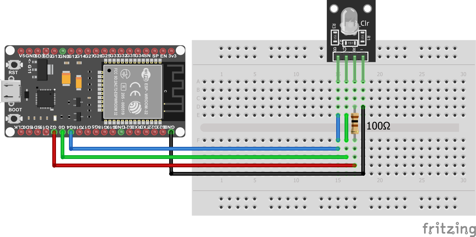
7 Color Flash LED KY-034 ESP32 NodeMCU
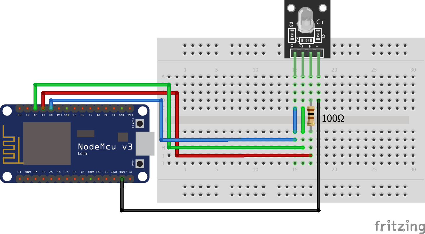
7 Color Flash LED KY-034 ESP8266 NodeMCU
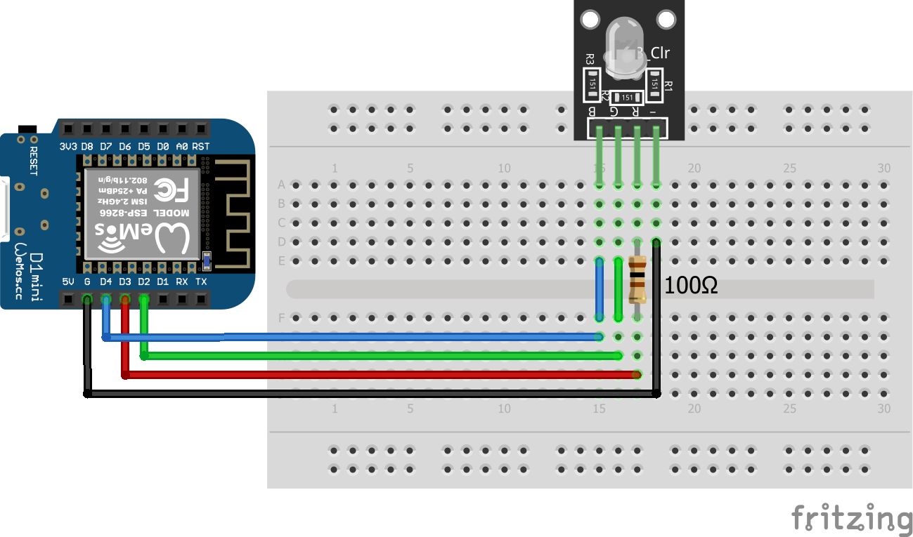
7 Color Flash LED KY-034 ESP8266 WeMos D1 Mini

Code for 7 Color Flash LED (KY-034) 20 Seconds Light Show

In the following example we turn on the LED for 20 seconds and then start the program all over again.

int Led_pin = 11; // for Arduino microcontroller
//int Led_pin = D6; // for ESP8266 microcontroller
//int Led_pin = 4; // for ESP32 microcontroller

void setup() {
  pinMode(Led_pin, OUTPUT);
}

void loop() {
  digitalWrite(Led_pin, HIGH);
  delay(20000);
}

Like in all other scripts, at the beginning we have to define the pin that connect the 7 color flash LED with the Arduino, EPS8266 or ESP32 micrcontroller. You only need the one line of code that matches to your microcontroller.

In the setup function we define the LED pin as output.

In the loop function, we turn on the logic of the 7 color flash LED by set the digital pin HIGH. After a delay of 20 seconds, we start the program all over again.

The following video shows the 7 color flash LED KY-034 in action. In my opinion this LED is the coolest of all in the article.

YouTube

By loading the video, you agree to YouTube's privacy policy.
Learn more

Load video

How to Use the Light Blocking (KY-010) Module

Light Blocking

The KY-010 photo interrupter module consists of an optical emitter/detector in the front and two resistors (1kΩ and 33Ω) in the back. The sensor uses a beam of light between the emitter and the detector to check if the path between both is being blocked by an opaque object.
The operation voltage is between 3.3V and 5V, therefore no resistor in series is needed to prevent burnout.

Wiring for Light Blocking (KY-010) Photo Interrupter

The following picture shows the wiring between the Light Blocking (KY-010) Photo Interrupter and different Arduino, ESP8266 and ESP32 microcontroller boards.

Light Blocking KY-010 Arduino Nano
Light Blocking KY-010 Arduino Pro Mini
Light Blocking KY-010 Arduino Uno
Light Blocking KY-010 Arduino Mega
Light Blocking KY-010 ESP32 NodeMCU
Light Blocking KY-010 ESP8266 NodeMCU
Light Blocking KY-010 ESP8266 WeMos D1 Mini

Code for KY-010 to Detect if Sensor Beam is Blocked

In the following example, the microcontroller will detect if the sensor beam is blocked. If this is true, a LED should turn on as long as the beam is blocked.

// for Arduino microcontroller
int Led = 8;           
int LightBlocker = 9;

// for ESP8266 microcontroller
//int Led = D7;           
//int LightBlocker = D6;

// for ESP32 microcontroller
//int Led = 4;           
//int LightBlocker = 0;


void setup() {
  pinMode(Led, OUTPUT);
  pinMode(LightBlocker, INPUT);
}

void loop() {
  int val = digitalRead(LightBlocker);
  if(val == HIGH) {
    digitalWrite(Led,HIGH);
  }
  else {
    digitalWrite(Led,LOW);
  }
}

In the first part of the Arduino script we define the pins that are connected to the LED and the light blocking module. The script can be used for Arduino, ESP8266 or ESP32 microcontrollers. You simply have to comment the lines that do not match to your microcontroller.

In the setup function we define the LED pin as output and the pin for the light blocking module as input.

The loop function starts with reading the digital state of the light blocking sensor. If the sensor value is 1 it equals to that  the light is blocked, we turn on the LED by setting the digital output value of the LED pin HIGH. In all other cases we set the LED pin LOW so that the LED is off.

The following video shows that the LED is turned on when I block the light of the light blocking module with a wire.

YouTube

By loading the video, you agree to YouTube's privacy policy.
Learn more

Load video

Conclusion

I hope that you now know the differences between the different LED modules that are available on the market. Because there are some major differences, you should know what LED fits your project right. If you have any questions about this article, please the use comment section below to ask some questions. And I would be really happe if you share this article with your friends.

Leave a Comment