Segment LED Display Tutorial for Arduino, ESP8266 and ESP32

In this tutorial you learn how the three most important segment LED displays work. We cover every segment display with examples and the correct wiring. The 3 different displays are:

  1. 7 Segment Display
  2. 4 7 Segment Display
  3. 8×8 Dot Matrix Display

Also this article cover the 74HC595 Shift Register which reduces the number of used pin on your microcontroller.

Segment LED Displays

Table of Contents

How to Use the 7 Segment Display

Seven segment displays are most used to display decimal numbers (0…9) in electronic displays like microwave ovens, calculators or washing machines. These kind of displays use light emitting diodes (LEDs) for every of the 7 segments. Therefore it is possible to display decimal numbers if the LEDs of the right segments are turned on.

The following picture shows the pinout of a 7 segment display to get a better understanding how it works.

7 Segment Display Pinout

The different segments are connected with the corresponding pins on the edge or backside of the display. The 2 middle pins are the common pins and connected to a common cathode or common anode. This depends of the kind of 7 segment display you have. In most cases you will have a common cathode display so that an LED turns on when the signal to the LED is HIGH and to common is connected to ground. If you have an anode segment display the LED turns on when the signal is LOW.

Note that your display might have a dot point on the right side so that in total you have 10 pins to connect to your microcontroller.

  • 1 pin for the dot pin
  • 7 pins for the different segments to display numbers
  • 2 pins to connect the anode or cathode

Wiring for 7 Segment Display with Arudino, ESP8266 and ESP32

The following fritzing sketches show the connection of the 7 segment LED display to an Arduino ESP8266 or ESP32 microcontroller.

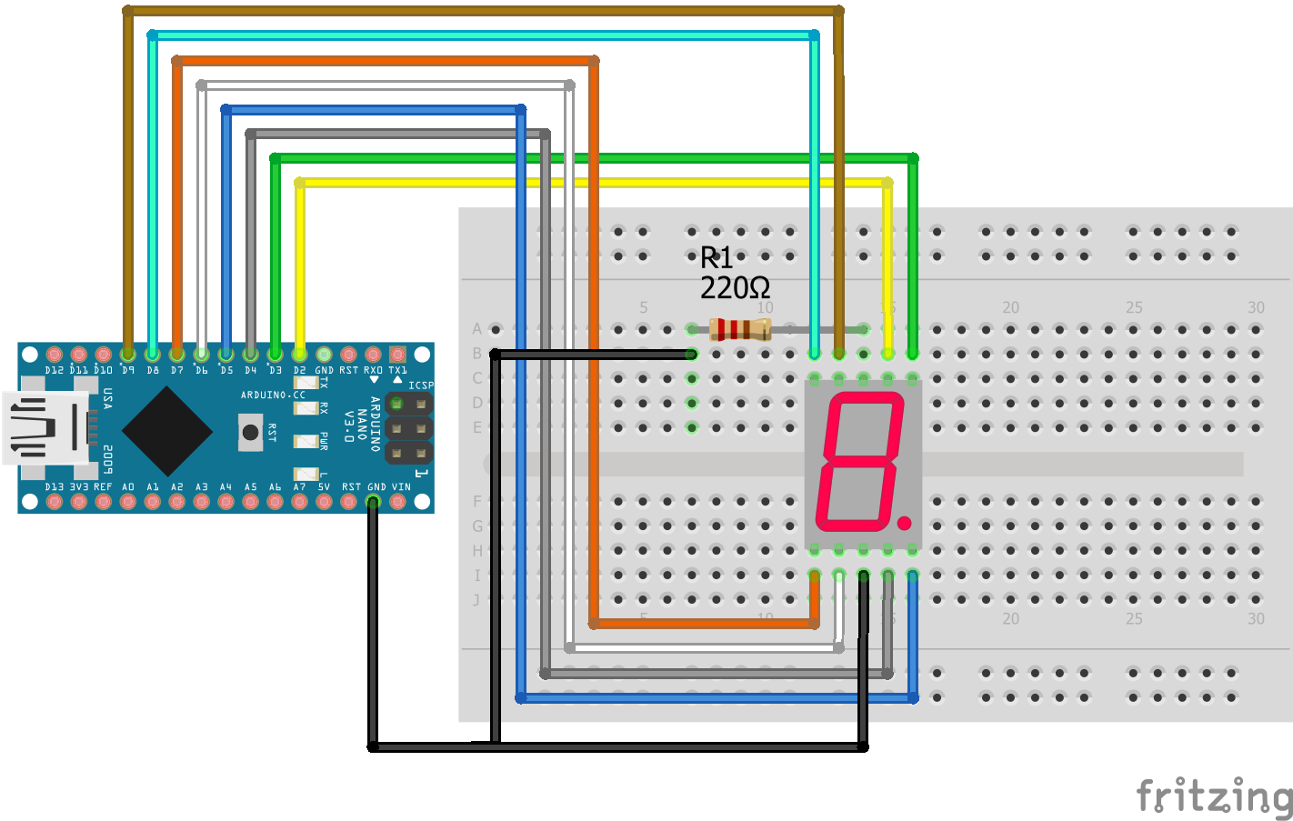
7 Segment LED Display Arduino Nano

For more information about the Arduino Nano, visit the Arduino Nano Tutorial.

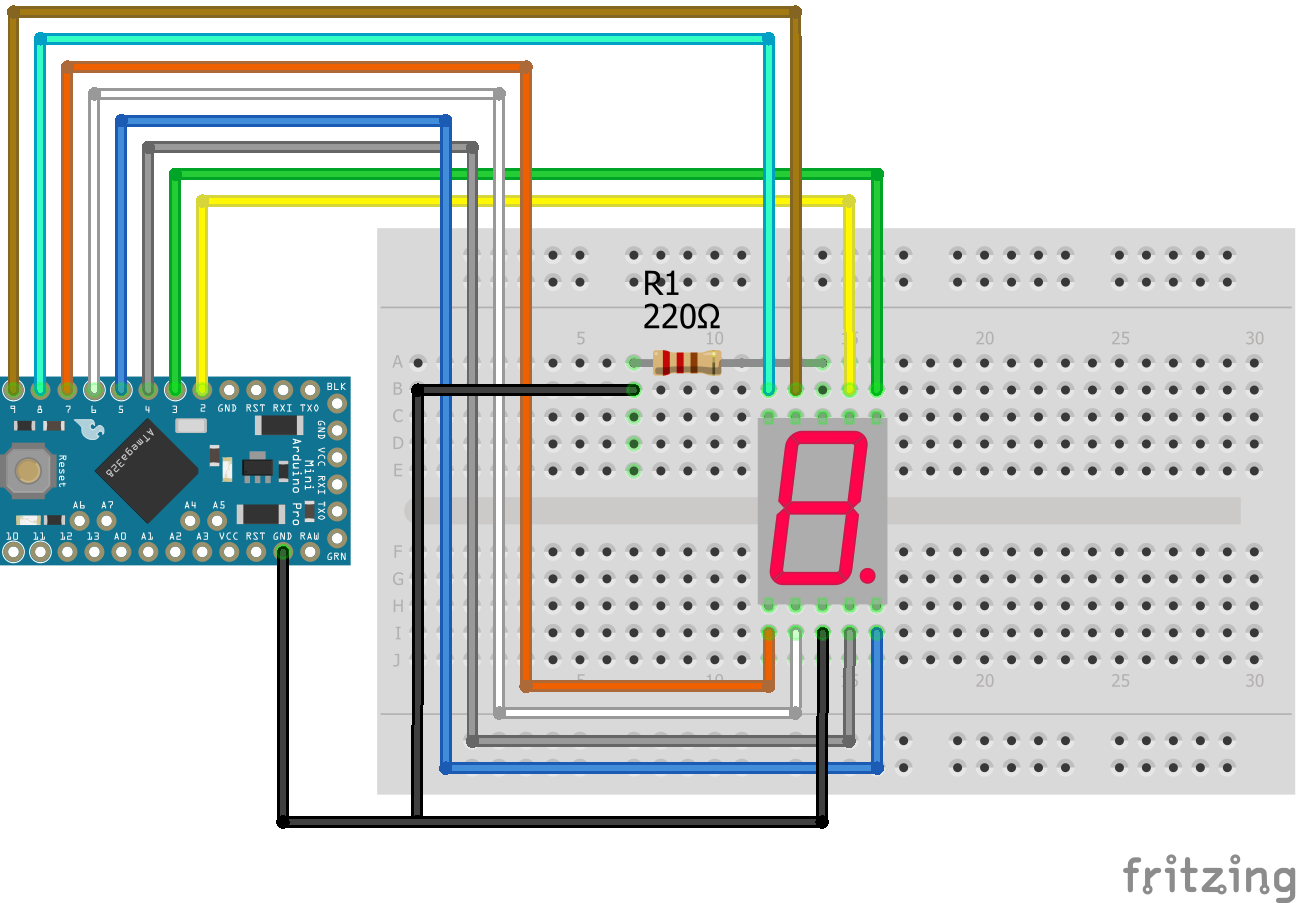
7 Segment LED Display Arduino Pro Mini
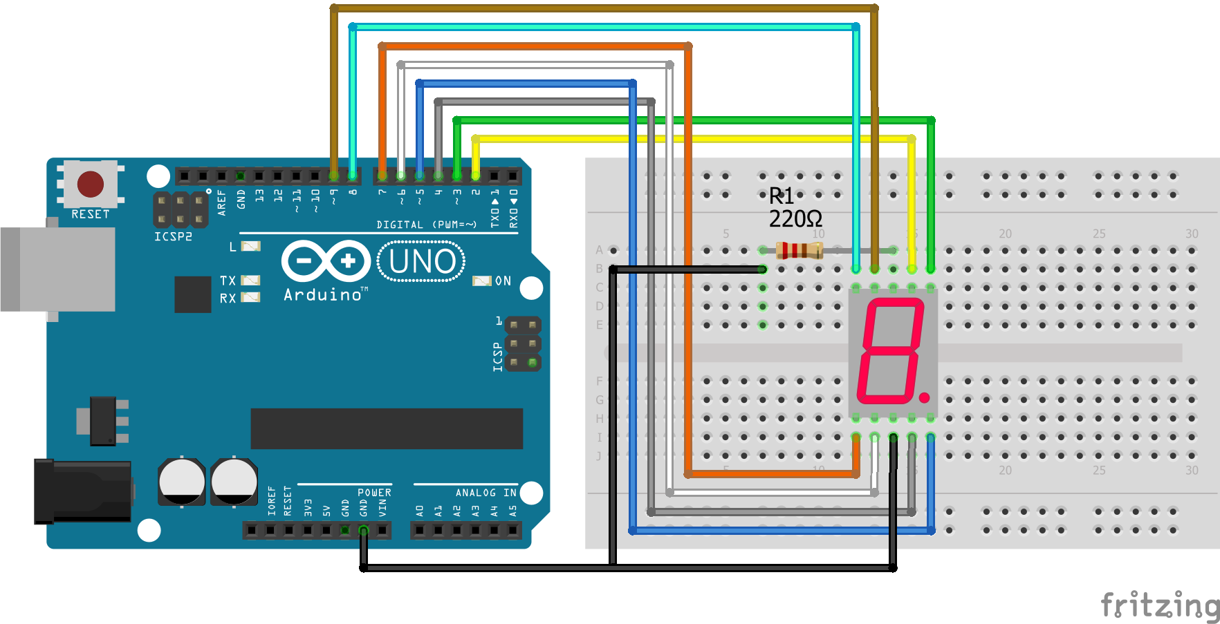
7 Segment LED Display Arduino Uno

For more information about the Arduino Uno, visit the Arduino Uno Tutorial.

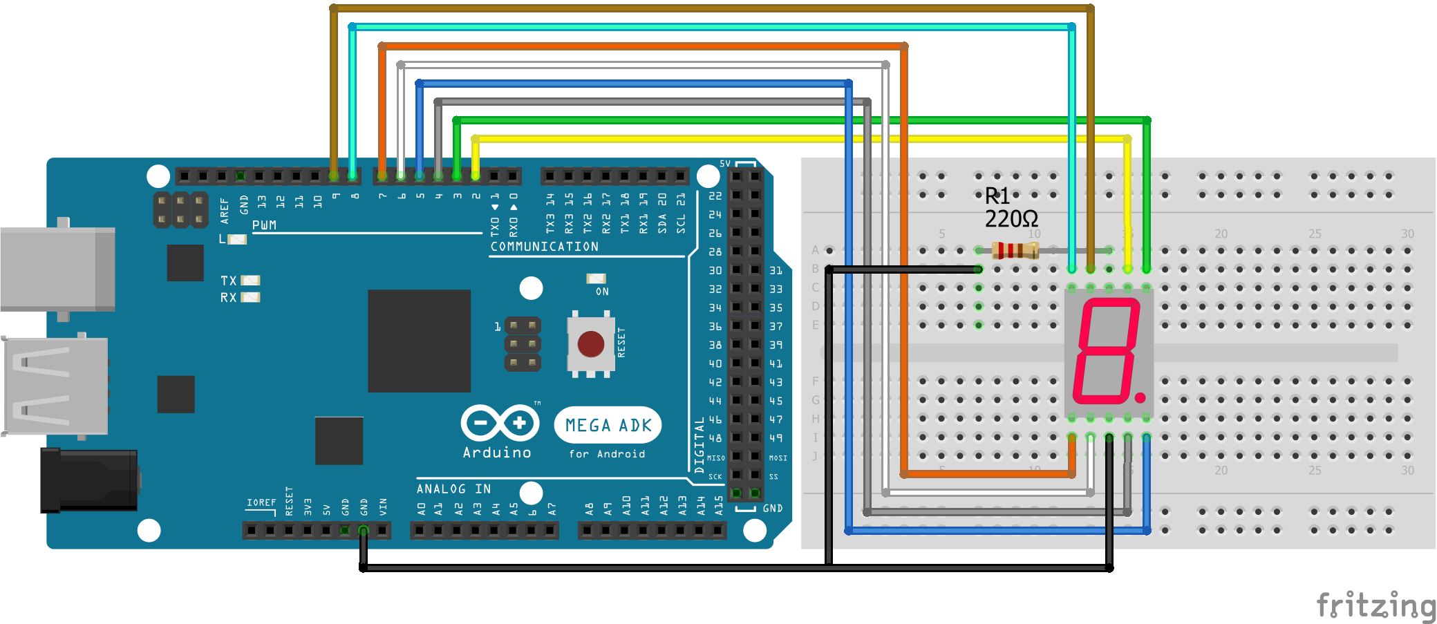
7 Segment LED Display Arduino Mega

For more information about the Arduino Mega, visit the Arduino Mega Tutorial.

7 Segment LED Display ESP32 NodeMCU
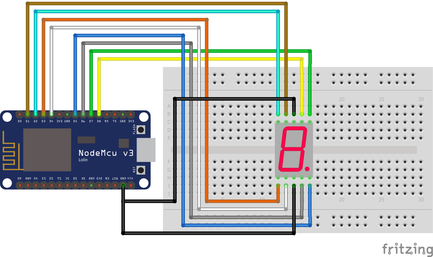
7 Segment LED Display ESP8266 NodeMCU
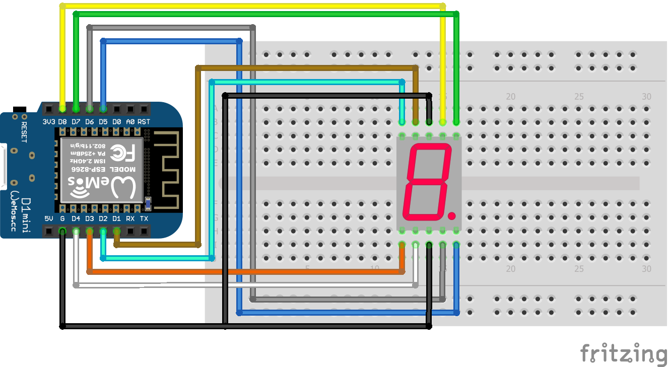
7 Segment LED Display ESP8266 WeMos D1 Mini

The 220 Ohm resistor between the common pin and ground restricts the current to less than 20mA for the Arduino microcontroller.

To display different kinds of numbers on the segment display it is useful to have a table for all numbers. Therefore the following table shows you the Bit and HEX Code for the anode and cathode configuration.

Anode configuration of display numbers
on a 7 segment display

Numberg f e d c b aHex Code
01000000C0
11111001F9
20100100A4
30110000B0
4001100199
5001001092
6000001082
71111000F8
8000000080
9001000090

Cathode configuration of display numbers
on a 7 segment display

Numberg f e d c b aHex Code
001111113F
1000011006
210110115B
310011114F
4110011066
511011016D
611111017D
7000011107
811111117F
910011114F

Code to Loop Numbers in 7 Segment Display

In the example we want to display some values. I used to display the numbers 1 and 8 in a loop. With the provided table you can easily change the following sketch to display other digital numbers.

int LEDs[] = {8,9,7,6,4,3,2};        // for Arduino microcontroller
//int LEDs[] = {D2,D1,D3,D4,D6,D7,D8}; // for ESP8266 microcontroller
//int LEDs[] = {22,23,1,3,19,18,5};    // for ESP32 microcontroller

int one[] = {0, 0, 0, 0, 1, 1, 0};   // LED states to display number one
int eight[] = {1, 1, 1, 1, 1, 1, 1}; // LED states to display number eight

void setup() {
  for (int i = 0; i<7; i++) pinMode(LEDs[i], OUTPUT);
}

void loop() {
  for (int i = 0; i<7; i++) digitalWrite(LEDs[i], one[i]);
  delay(1000);
  for (int i = 0; i<7; i++) digitalWrite(LEDs[i], eight[i]);
  delay(1000);
}

The script is a bit tricky if you did not use arrays before. Therefore I explain the Arduino script in detail.

At the beginning of the script we create an array, called LEDs that stores all the connection pins to the 7 segment display. Later we can access every element in the array to make our lives a little easier. Depending on your microcontroller, you only have to select one of the first three lines. You can either comment the other lines or delete them, if you do not need them.

Because we want to display the numbers 1 and 8, we have to define how to control all digital I/O pins to get the desired numbers. You can use the table for the anode or cathode configuration to see which of the 7 pins has to be 0 (LOW) or 1 (HIGH). Because my 7 segment display has a cathode configuration, the 1 is displayed with 0000110 and 8 with 1111111. We save the combination of values also in an array.

In the setup function we define each pin that connects the microcontroller and the display as output, because we want to control the display from the view of the microcontroller. You could define each pin as output separat line after line, but we have our array that makes the definition as output very easy. We only have to loop through the LEDs array with a for loop and set the pinMode of the desired element in the array as output.

In the loop function, we now have to control the digital output pins with LOW and HIGH signals so that a 1 and 8 shows up in the 7 segment display.

Therefore we loop again over the previous created arrays in a for loop. We use the digitalWrite function to go step by step over the arrays and change the first element, that is the first pin to the first status of the array that creates the number. For example for Arduino microcontrollers:

  • i=0: set LEDs[0] = pin8 to one[0] = LOW
  • i=5: set LEDs[5] = pin3 to one[1] = HIGH

After we created the digit in the segment display, we use a delay of one second before we create the next digit or restart the loop function.

The following video shows the digits 1 and 8 that are created in the 7 segment display.

YouTube

By loading the video, you agree to YouTube's privacy policy.
Learn more

Load video

The following table gives you an overview of all components and parts that I used for this tutorial. I get commissions for purchases made through links in this table.

ComponentAmazon LinkAliExpress Link
Arduino Nano AmazonAliExpress
Arduino Pro Mini AmazonAliExpress
Arduino Uno AmazonAliExpress
Arduino Mega AmazonAliExpress
ESP32 ESP-WROOM-32AmazonAliExpress
ESP8266 NodeMCU AmazonAliExpress
ESP8266 WeMos D1 Mini AmazonAliExpress
7 and 4x7 Segment Display (in Sensor Kit) AmazonAliExpress
8x8 Dot Matrix Display AmazonAliExpress

Why you should not use the 4x7 Segment Display

The 4 times 7 Segment Display is easy explained. It is 4 times the 7 segment display in a row. Therefore a lot of wiring is necessary. For me personally if the wiring gets to complicated, I try to find an other way to get to my goal. And for me I prefer an LCD display which is easy to wire with I2C instead of the complicated use and blocking pins of the 4 7 segment display. If you want to learn how to use the LCD display, I also have a tutorial for LCD displays.

How to Reduce the Number of Pins of a Segment Display

Also there is a possibility to reduce the number of pins you need to connect the segment displays to your microcontroller. With the use of shift registers like the 74HC595 it is possible to declare the status of each LED with one 8-bit number rather than use one bit for every LED. With the use of a shift register you can reduce the number of pins from 8 to only 3.

Use the 74HC595 Register to Reduce the Number of Pins

The 74HC595 is a serial-in parallel-out register that reduces the number of outgoing pins of the microcontroller. You can view the datasheet of the 74HC595 or read my tutorial on shift register to get detailed information.

The operating voltage is between 2V and 6V. Therefore the 74HC595 can be used with all Arduino, ESP8266 and ESP32 microcontroller. Also the power consumption is low with 80 micro A and the shift register can directly clear the complete output.

Wiring between Segment Display, 74HC595 and Microcontroller

The following table and pictures show the connection between the 74HC595, the 7 segment display and the Arduino, ESP8266 or ESP32 microcontroller.

SymbolDescriptionConnection ArduinoConnection ESP8266Connection ESP32
QBShift register output LED b7 SD: Pin b7 SD: Pin b7 SD: Pin b
QCShift register output LED c7 SD: Pin c7 SD: Pin c7 SD: Pin c
QDShift register output LED d7 SD: Pin d7 SD: Pin d7 SD: Pin d
QEShift register output LED e7 SD: Pin e7 SD: Pin e7 SD: Pin e
QFShift register output LED f7 SD: Pin f7 SD: Pin f7 SD: Pin f
QGShift register output LED g7 SD: Pin g7 SD: Pin g7 SD: Pin g
QHShift register output LED P
GNDGroundGNDGNDGND
QHOutput if more
SRCLRClear the register when LOW5V3.3V3.3V
SRCLKStorage register clockClock: Pin 2Clock: Pin D8Clock: Pin 4
RCLKShift register clockLatch: Pin 3Latch: Pin D7Latch: Pin 0
OEOutput enable when groundGNDGNDGND
SERSerial input for next pinData: Pin 4Data: Pin D6Data: Pin 2
QAShift register output LED a7 SD: Pin a7 SD: Pin a7 SD: Pin a
VCC5V supply5V3.3V3.3V

If you want to know more about the pinout of different microcontroller, I wrote an article about the different pinouts of EPS8266 boards, Arduino Nano, Arduino Uno, Arduino Mega. But if you are actually interested in the different microcontroller, you take a look at the Microcontroller Datasheet eBook.

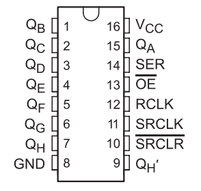
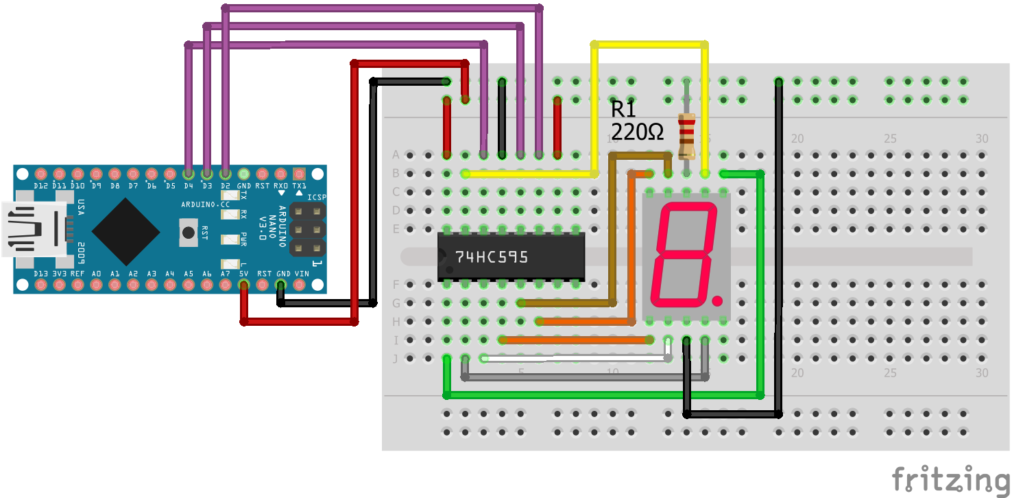
7 Segment LED Display Shift Register Arduino Nano

For more information about the Arduino Nano, visit the Arduino Nano Tutorial.

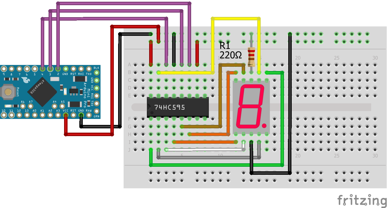
7 Segment LED Display Shift Register Arduino Pro Mini
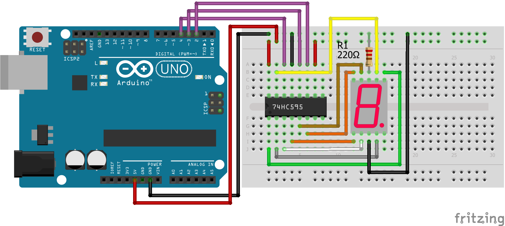
7 Segment LED Display Shift Register Arduino Uno

For more information about the Arduino Uno, visit the Arduino Uno Tutorial.

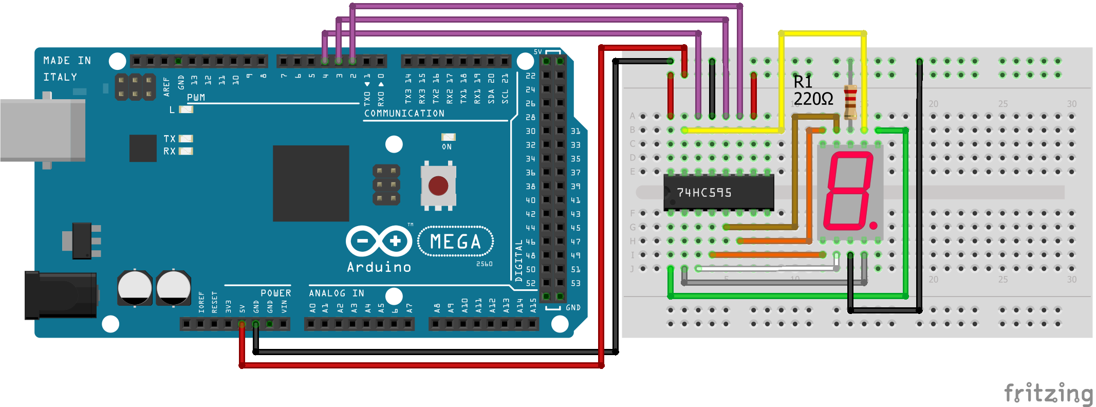
7 Segment LED Display Shift Register Arduino Mega

For more information about the Arduino Mega, visit the Arduino Mega Tutorial.

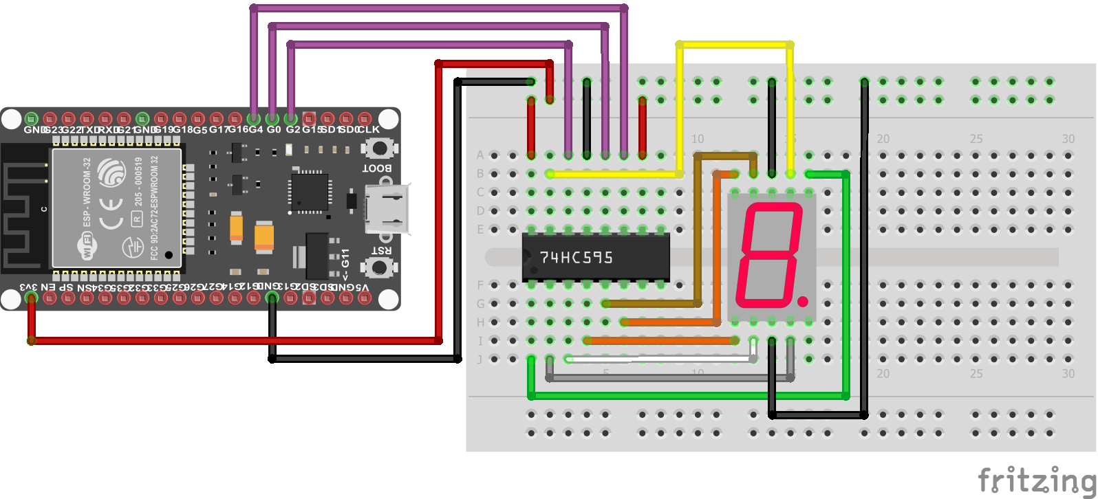
7 Segment LED Display Shift Register ESP32 NodeMCU
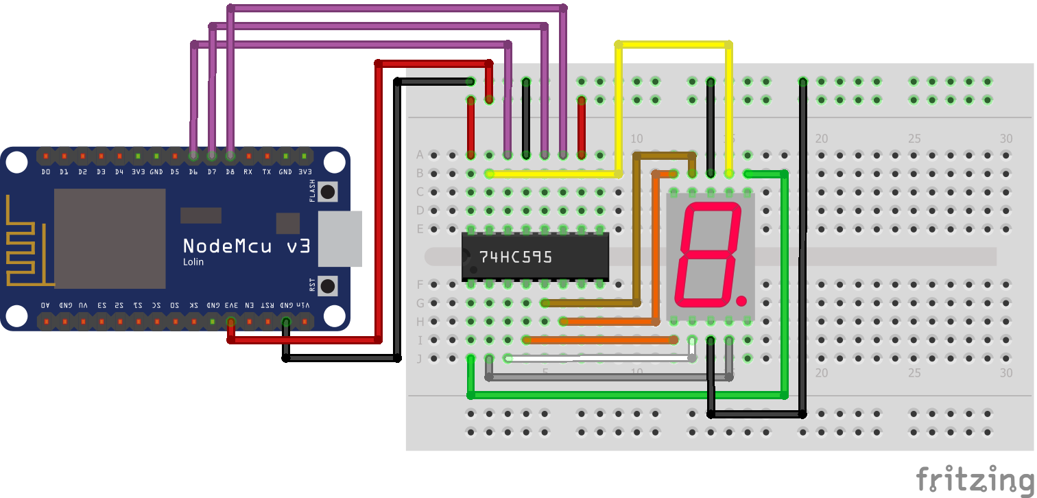
7 Segment LED Display Shift Register ESP8266 NodeMCU
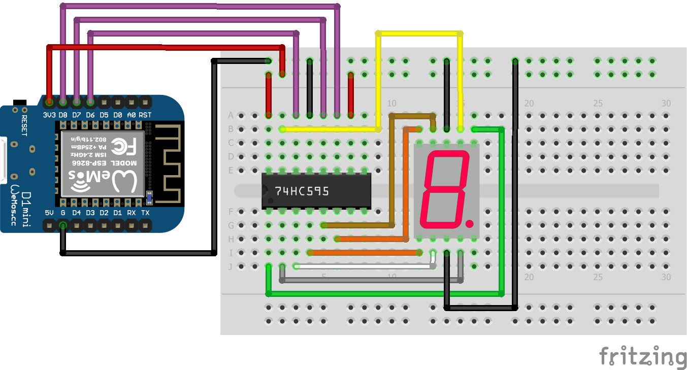
7 Segment LED Display Shift Register ESP8266 WeMos D1 Mini

Microcontroller Datasheet eBook

The 35 pages Microcontroller Datasheet Playbook contains the most useful information of 14 Arduino, ESP8266 and ESP32 microcontroller boards.

How to Control the 74HC595 Shift Register

The function of a shift register is the following:

  • The shift register loads the state (HIGH or LOW) of each LED one by one with the data pin (DATA) as long as the clock (LATCH) is set to LOW.
  • The loading of each LED is controlled by the storage register clock (CLOCK).
  • After all 8 LEDs states are loaded, the shift register clock (LATCH) is set from LOW to HIGH.

For the following sketch we have one thing left to define. The shift register has to know if want to load the most significant bit first (MSBFIRST) or last (LSBFIRST). The following tables explain the difference. We want to load the number 3 into the shift register:

MSBFIRST the number 3 in binary is 01001111

QAQBQCQDQEQFQGQH
Clear
Shift 1 → 0
Shift 2 → 11
Shift 3 → 01
Shift 4 → 01
Shift 5 → 111
Shift 6 → 1111
Shift 7 → 11111
Shift 8 → 111111

LSBFIRST the number 3 in binary is 11110010

QAQBQCQDQEQFQGQH
Clear
Shift 1 → 11
Shift 2 → 111
Shift 3 → 1111
Shift 4 → 11111
Shift 5 → 01111
Shift 6 → 01111
Shift 7 → 111111
Shift 8 → 011111

We use the MSBFIRST in the following example to display the values 0 to 4. Note that you can either define the decimal number in binary or HEX format. I use the HEX format in the following script.

Code to Reduce Number of Pins for Segment Display

// for Arduino microcontroller
int clockPin = 2;
int latchPin = 3;
int dataPin = 4;

// for ESP8266 microcontroller
//int clockPin = D8;
//int latchPin = D7;
//int dataPin = D6;

// for ESP32 microcontroller
//int clockPin = 4;
//int latchPin = 0;
//int dataPin = 2;

int num[] = {0x3F, 0x06, 0x5B, 0x4F, 0x66};

void setup() {
  pinMode(clockPin, OUTPUT);
  pinMode(latchPin, OUTPUT);
  pinMode(dataPin, OUTPUT);
}

void loop() {
  for (int i = 0; i<5; i++) {
    digitalWrite(latchPin, LOW);
    shiftOut(dataPin, clockPin, MSBFIRST, num[i]);
    digitalWrite(latchPin, HIGH);
    delay(1000);
  }
}

In the first part of the script, we have to define which pins are connected between the 74HC595 shift register and the microcontroller. Therefore the first lines are duplicated for Arduino, ESP8266 and ESP32 microcontroller. You simply have to select your microcontroller and delete the other lines or comment the lines, like I did.

To display the values 0 to 4 I store the HEX values of the digits in a array called num

In the setup function we set all connected digital I/O pins as output.

In the loop function we have to iterate through the num array to display all digits before the loop function starts again. For each element in the num array we set the latch pin low to load the different states of the shift register. Now we use the shiftOut function, shiftOut(dataPin, clockPin, bitOrder, value), to shift out a byte of data one bit at a time (reference):

  • dataPin: the pin on which to output each bit. Allowed data types: int.
  • clockPin: the pin to toggle once the dataPin has been set to the correct value. Allowed data types: int.
  • bitOrder: which order to shift out the bits; either MSBFIRST or LSBFIRST
  • value: the data to shift out. Allowed data types: byte.

After all states for the LED are loaded to the shift register, the shift register clock (LATCH) is set from LOW to HIGH to forward all values to the 7 segment display for the visualization.

The following video shows how the values 0 to 4 are displayed in the segment display with the use of an Arduino Uno and the 74HC595 shift register.

YouTube

By loading the video, you agree to YouTube's privacy policy.
Learn more

Load video

How to Use the 8x8 Dot Matrix Display

The 8×8 Dot Matrix Display has in total 64 LEDs and normally 16 pins. But I bought the module version of the dot matrix display, so that the dot matrix itself is connected to a shift register. Therefore we only have to connect 5 pins to our microcontroller. On the other side of the dot matrix display, the module has the same connection because you are able to connect multiple 8×8 Dot Matrix Display modules in a row, called daisy chain.

Wiring between 8x8 Dot Matrix Display and Microcontroller

The following pictures shows the connection between 8×8 dot matrix display in the module version and different Arduino, ESP8266 and ESP32 microcontroller boards.

8x8 Dot Display Arduino Nano
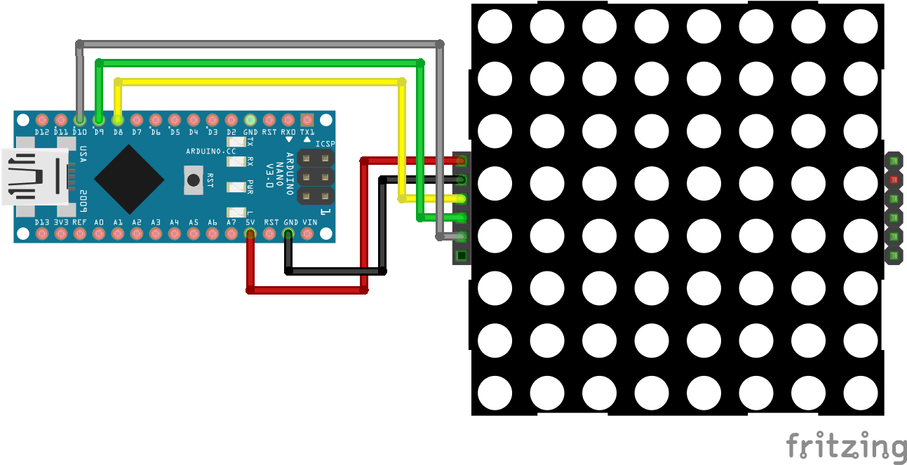
8×8 Dot Display Arduino Nano

For more information about the Arduino Nano, visit the Arduino Nano Tutorial.

8x8 Dot Display Arduino Pro Mini
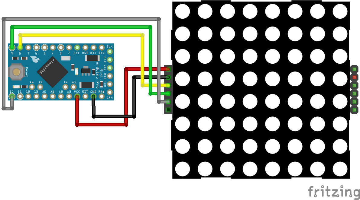
8×8 Dot Display Arduino Pro Mini
8x8 Dot Display Arduino Uno
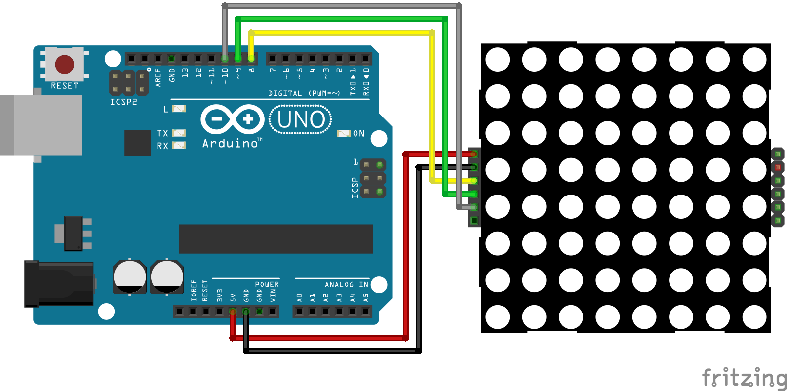
8×8 Dot Display Arduino Uno

For more information about the Arduino Uno, visit the Arduino Uno Tutorial.

8x8 Dot Display Arduino Mega
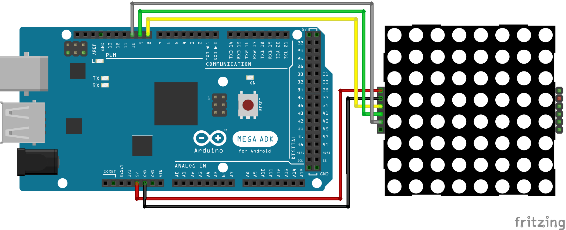
8×8 Dot Display Arduino Mega

For more information about the Arduino Mega, visit the Arduino Mega Tutorial.

8x8 Dot Display ESP32 NodeMCU
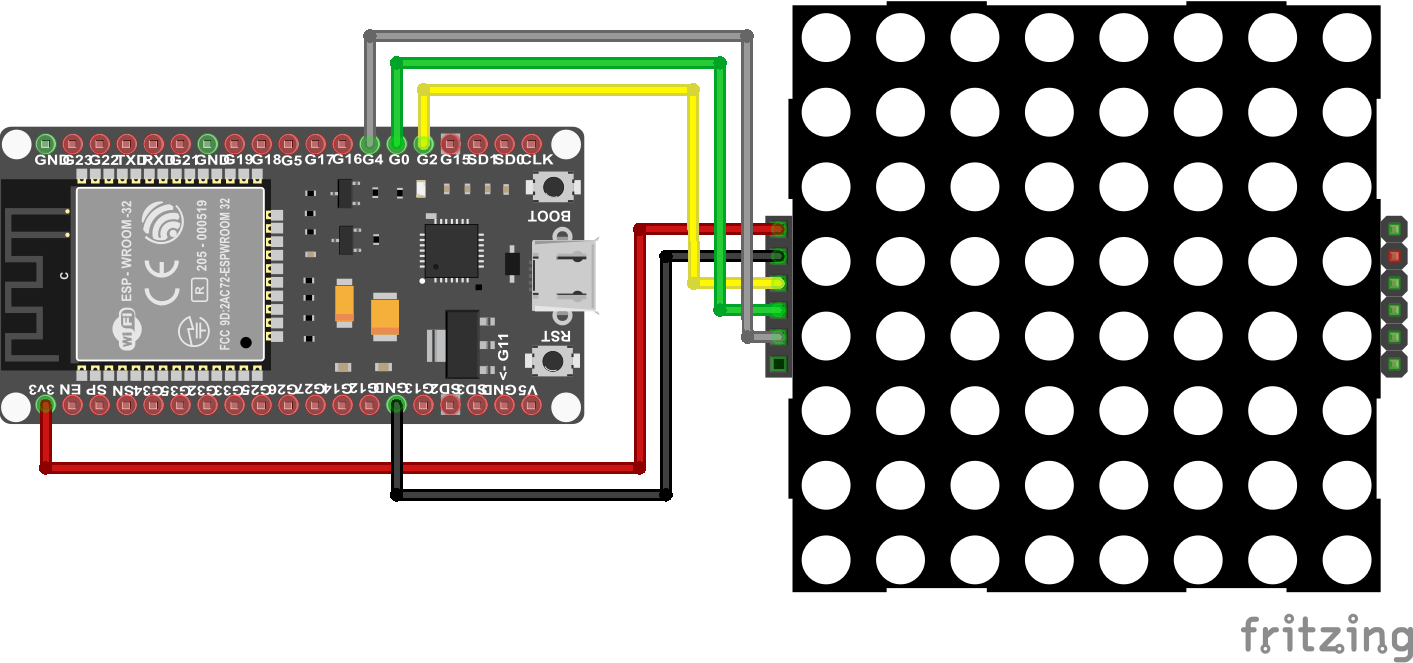
8×8 Dot Display ESP32 NodeMCU
8x8 Dot Display ESP8266 NodeMCU
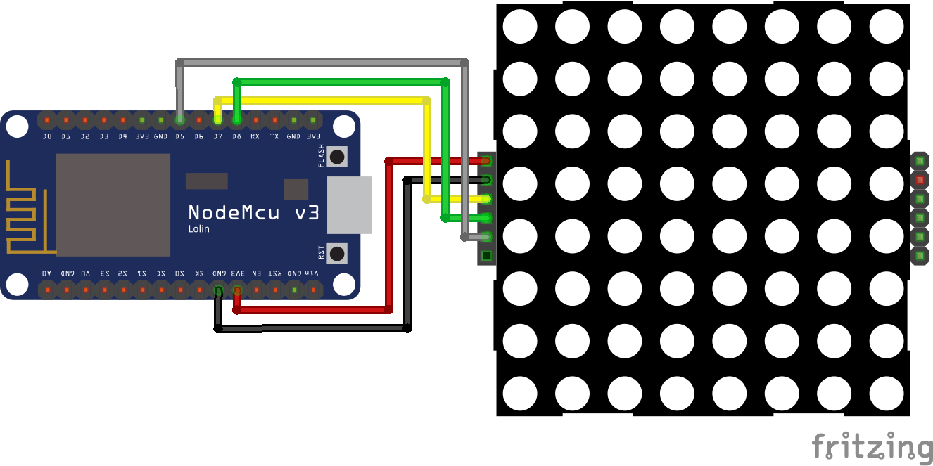
8×8 Dot Display ESP8266 NodeMCU
8x8 Dot Display ESP8266 WeMos D1 Mini
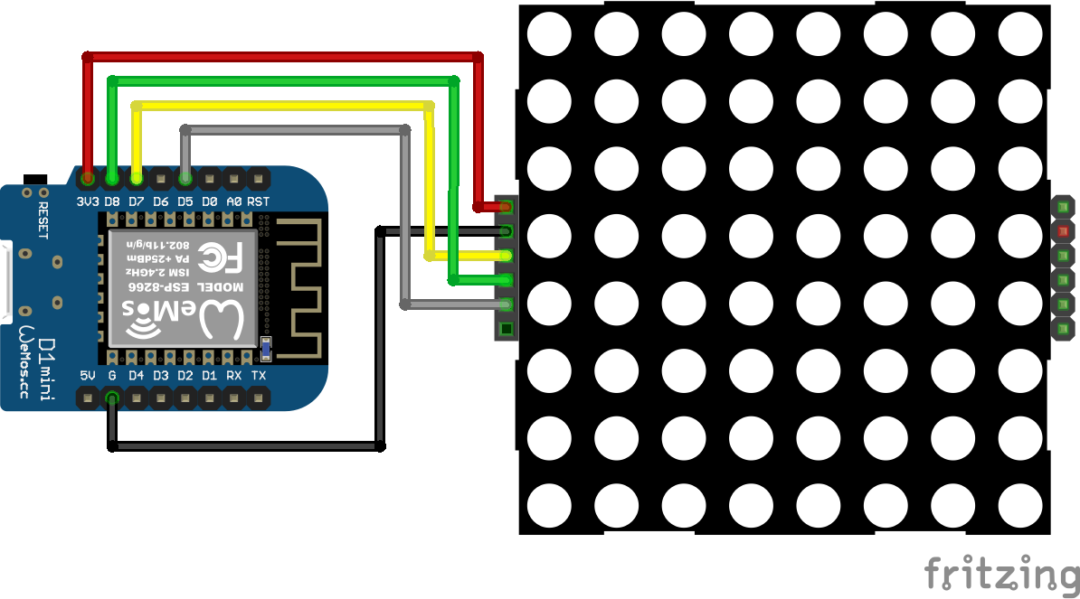
8×8 Dot Display ESP8266 WeMos D1 Mini

The easiest way to control the display is with the LedControl library. If you do not know how to install an external library to your Arduino IDE, here is a step by step tutorial.

Code to Show Smiley in 8x8 Dot Matrix Display

In the following example we display a sad, a neural and a happy smiley in the 8×8 dot matrix display.

#include "LedControl.h"
#include "binary.h"

LedControl lc=LedControl(8,10,9,1); // for Arduino microcontroller
//LedControl lc=LedControl(D7,D5,D8,1); // for ESP8266 microcontroller
//LedControl lc=LedControl(2,4,0,1); // for ESP32 microcontroller

byte hf[8]= {B00111100,B01000010,B10100101,B10000001,B10100101,B10011001,B01000010,B00111100};
byte nf[8]={B00111100, B01000010,B10100101,B10000001,B10111101,B10000001,B01000010,B00111100};
byte sf[8]= {B00111100,B01000010,B10100101,B10000001,B10011001,B10100101,B01000010,B00111100};

void setup() {
  lc.shutdown(0,false);
  lc.setIntensity(0,5);
  lc.clearDisplay(0);  
}

void loop() {
  for (int i = 0; i<8; i++) lc.setRow(0,i,sf[i]); // Display sad face
  delay(1000);
  for (int i = 0; i<8; i++) lc.setRow(0,i,nf[i]); // Display neutral face
  delay(1000);
  for (int i = 0; i<8; i++) lc.setRow(0,i,hf[i]); // Display happy face
  delay(1000);
}

At the beginning of the script we include the library LedControl to use functions for controlling the 8×8 dot matrix display and binary to use binary codes values in the script.

Now we create an object LedControl and define the connection pins between the dot matrix display and the microcontroller. Because this script can be used with Arduino, ESP8266 or ESP32 microcontrollers, you have to uncomment the line that suits for your microcontroller and delete or comment the other lines of code. The last parameter defines how many displays are connected. In our case just the one and therefore is the last parameter 1.

In the next part of the script we define the arrays that contain the binary codes which LED dots should turn on to create a happy face (hf), a neural face (nf) and a sad face (sf). Each array has 8 elements for a 8×8 dot matrix display.

In the setup function we set the power saving mode to false that can be called with the shutdown function. Also the brightness can be controlled with the setIndensity function between 0 and 15. We set the brightness to a medium value of 5. In the last step of the setup function we make sure that alle LEDs are turned off with the clearDisplay function.

In the loop function we start to draw the three faces. Like in the first example, we only have to loop over the 8 rows of the dot matrix display and define which LEDs should turn on. This is done by the setRow function, that has the row and the corresponding element of the smiley array as argument. Between each smiley we wait for 1 second.

The following videos shows the three different faces that appear in the 8×8 dot matrix display.

YouTube

By loading the video, you agree to YouTube's privacy policy.
Learn more

Load video

Use the LED Matrix Editor to Auto Create the Program Code

Do you think that the way to choose the LEDs which should turn on is complicated? Yes you are right, but there is an easier way to make the program sketch. On LED Matrix Editor you can select each LED and insert different patterns into a recorder.

The following video shows how to select different patterns. After you created one pattern you can press the button insert to save this pattern to the list. Now you create a second one and insert this also in the list. After you are done, press the update button to update the Arduino code from the right side.

YouTube

By loading the video, you agree to YouTube's privacy policy.
Learn more

Load video

If you scroll down the page you find different examples for the whole program code. You simply have to change the image array IMAGES.

The following program code shows how I created another example for the 8×8 dot matrix display.

#include "LedControl.h"
#include "binary.h"

LedControl lc=LedControl(8,10,9,1); // for Arduino microcontroller
//LedControl lc=LedControl(D7,D5,D8,1); // for ESP8266 microcontroller
//LedControl lc=LedControl(2,4,0,1); // for ESP32 microcontroller

const uint64_t IMAGES[] = {
  0x0000000000000000,
  0xff000000000000ff,
  0x8142241818244281
};
const int IMAGES_LEN = sizeof(IMAGES)/8;

void setup() {
  lc.clearDisplay(0);
  lc.shutdown(0, false);
  lc.setIntensity(0, 10);
}

void displayImage(uint64_t image) {
  for (int i = 0; i < 8; i++) {
    byte row = (image >> i * 8) & 0xFF;
    for (int j = 0; j < 8; j++) {
      lc.setLed(0, i, j, bitRead(row, j));
    }
  }
}

int i = 0;

void loop() {
  displayImage(IMAGES[i]);
  if (++i >= IMAGES_LEN ) {
    i = 0;
  }
  delay(200);
}
YouTube

By loading the video, you agree to YouTube's privacy policy.
Learn more

Load video

Conclusion

In this article you learned how to use the 7 Segment Display as well as the 8×8 Dot Matrix Display. We discovered how to use the Shift Register to reduce the number of pins on your microcontroller and why you should not use the 4 7 Segment Display.
If you have any questions regarding segment displays or the sketches in this article, feel free to ask your question in the comment section below. I will answer all questions as soon as possible.

3 thoughts on “Segment Display Tutorial for Arduino, ESP8266 and ESP32”

  1. Thanks, its a great summary, would be nice add simple example of 4×7 segment with 74HC595 and ESP8266. I’ve problem on timing between 4 segment, can’t make it sync each segment shows it number, it is over write to each other.

    Reply

Leave a Comment