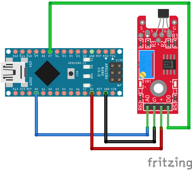
Linear Hall Sensor KY-024 Arduino Nano
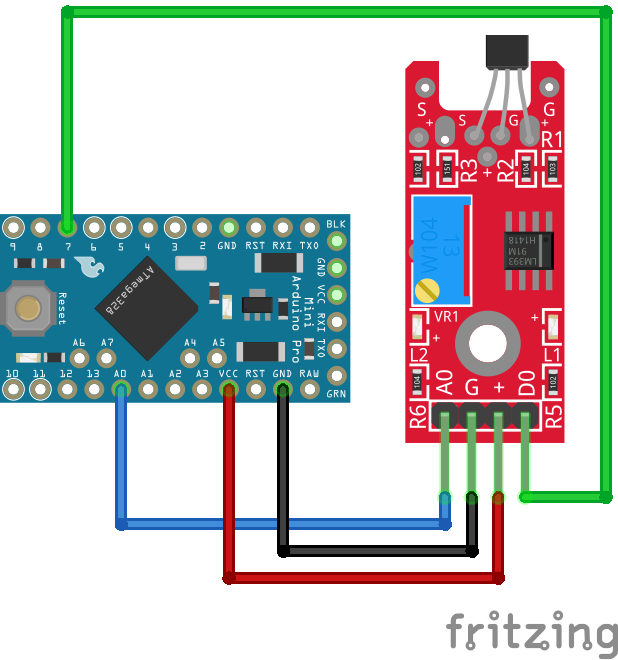
Linear Hall Sensor KY-024 Arduino Pro Mini
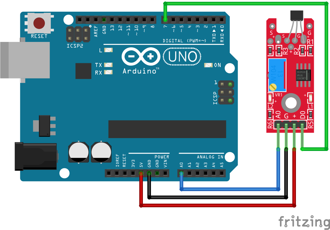
Linear Hall Sensor KY-024 Arduino Uno
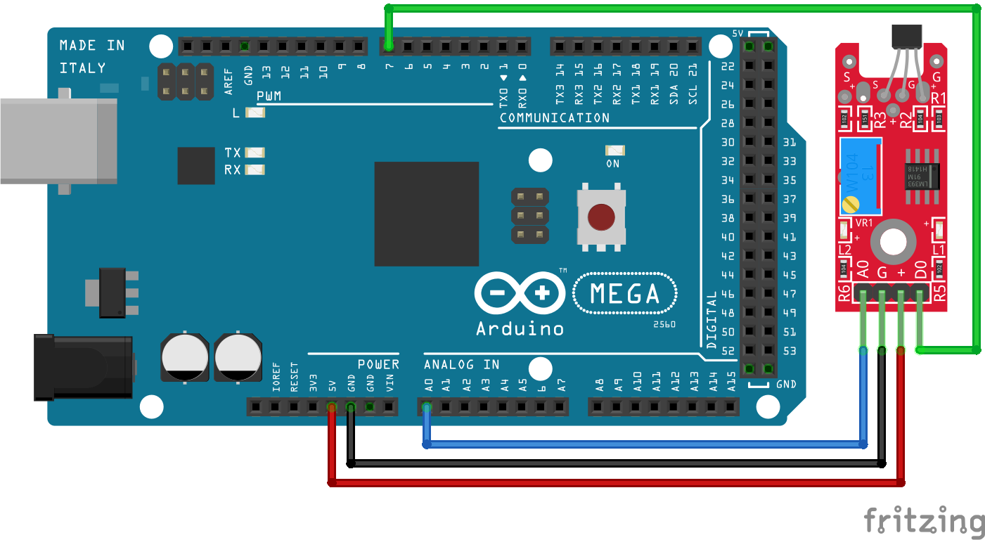
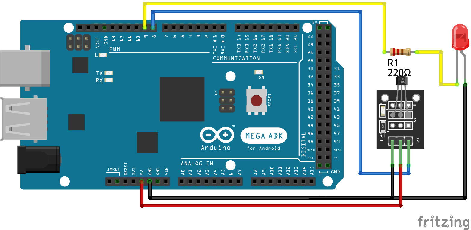
Linear Hall Sensor KY-024 Arduino Mega

Linear Hall Sensor KY-024 ESP32 NodeMCU
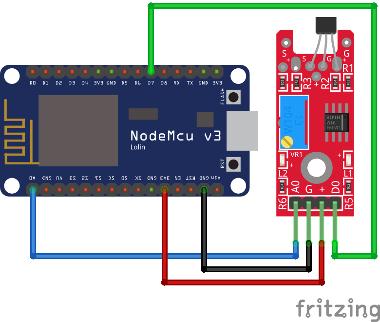
Linear Hall Sensor KY-024 ESP8266 NodeMCU
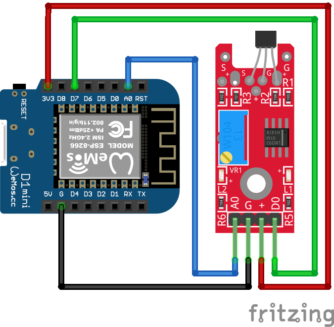
Linear Hall Sensor KY-024 ESP8266 WeMos D1 Mini

Magnetic Hall Sensor KY-003 Arduino Nano

Magnetic Hall Sensor KY-003 Arduino Pro Mini

Magnetic Hall Sensor KY-003 Arduino Uno
Magnetic Hall Sensor KY-003 Arduino Mega
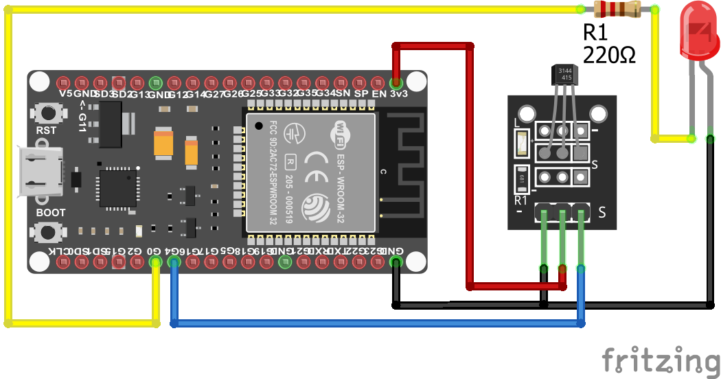
Magnetic Hall Sensor KY-003 ESP32 NodeMCU
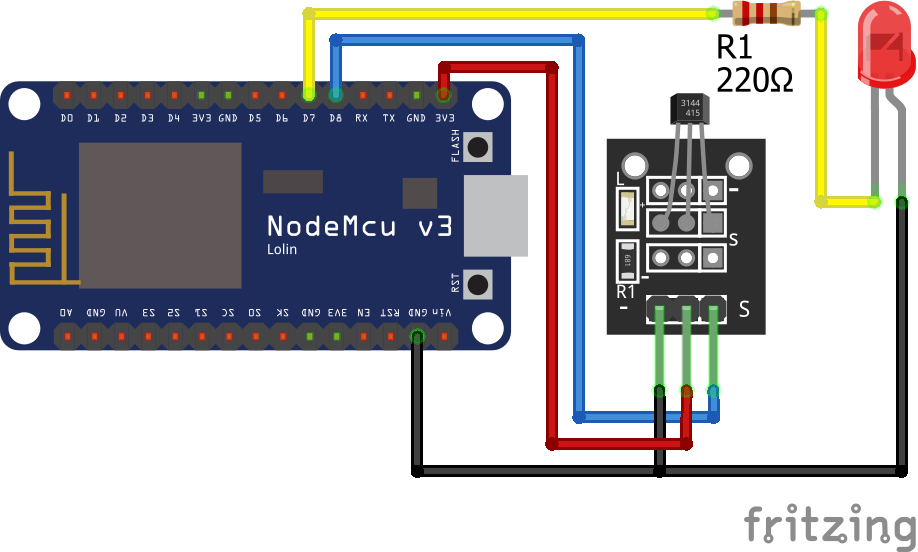
Magnetic Hall Sensor KY-003 ESP8266 NodeMCU
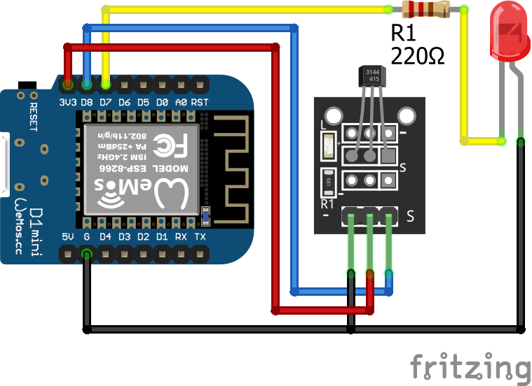
Magnetic Hall Sensor KY-003 ESP8266 WeMos D1 Mini
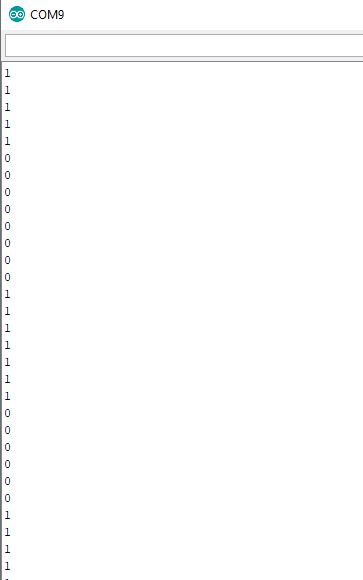
Hi! I was wondering what exactly the unit is that’s recorded by the Linear Hall Sensor – the one that equates 5V to 1023?
Yes, the onboard Analog to Digital converter converts the voltage to a digital value between 0 and 1023 where 5V is equivalent to 1023.
Can the Hall sensor output (5V) be connected to the input of an ESP (3.3V)?
Hi Gabriel, yes the Hall sensor can be operated with 5V as well as 3.3V
Just to clarify, you can operate the depicted linear Hall sensor module with 3.3 or 5 Volts. But DO NOT feed a 5V-powered Hall sensor output into a 3.3V logic. You would need a logic level converter in between the two.
Thank you very much for this tutorial! I tried it myself with the KY-024 Hall sensor. Here my result: https://nerd-corner.com/hallsensor-ky-024-arduino-code/