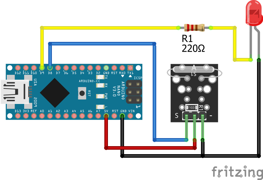
KY-025 Arduino Nano

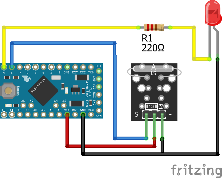
KY-025 Arduino Pro Mini
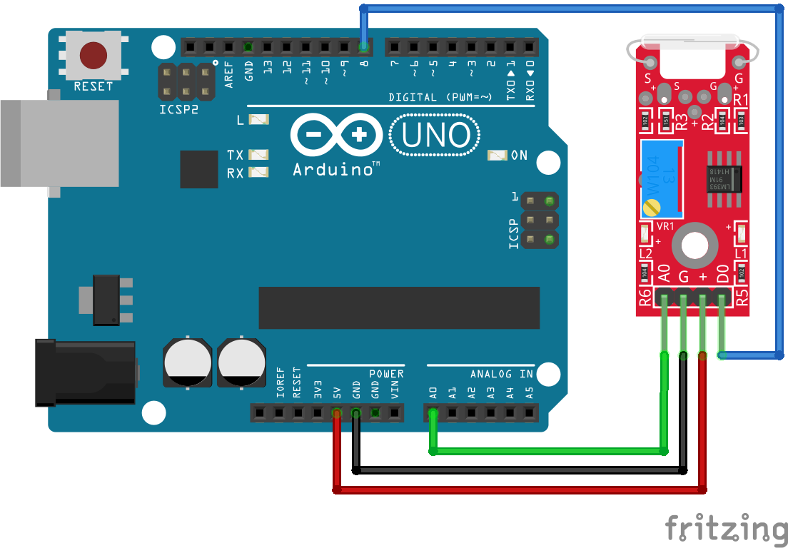
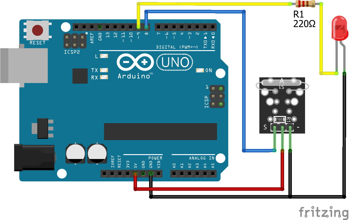
KY-025 Arduino Uno
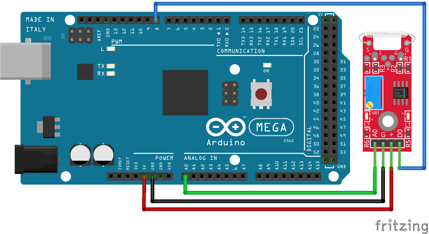
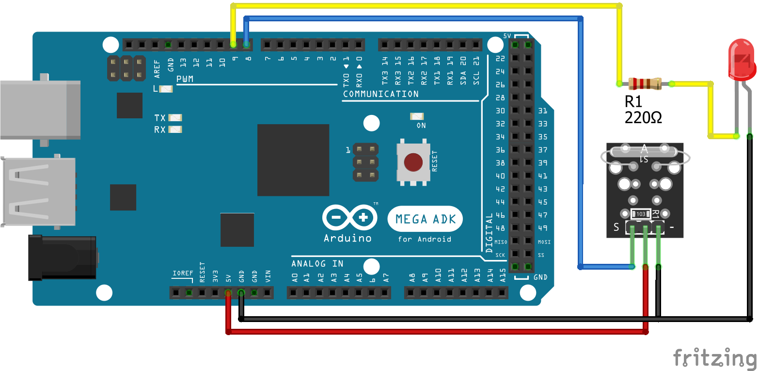
KY-025 Arduino Mega
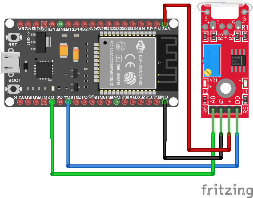
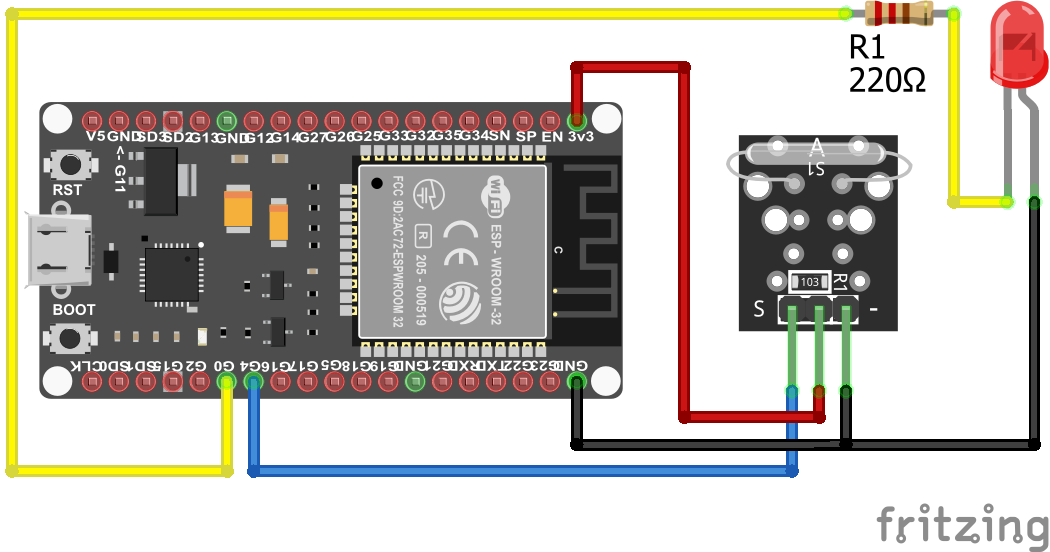
KY-025 ESP32 NodeMCU
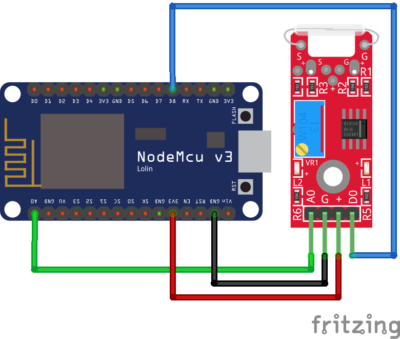
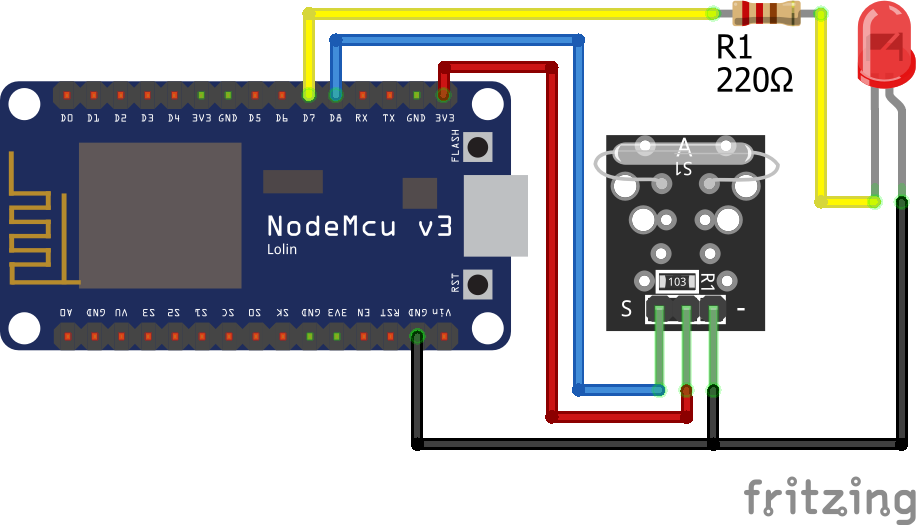
KY-025 ESP8266 NodeMCU
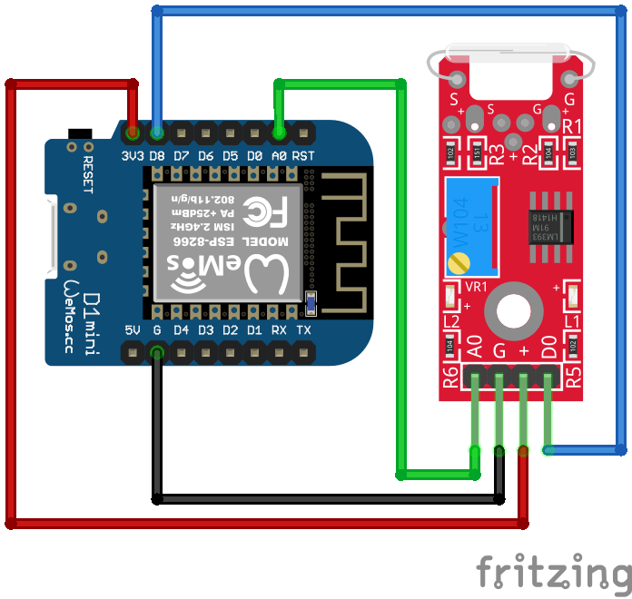
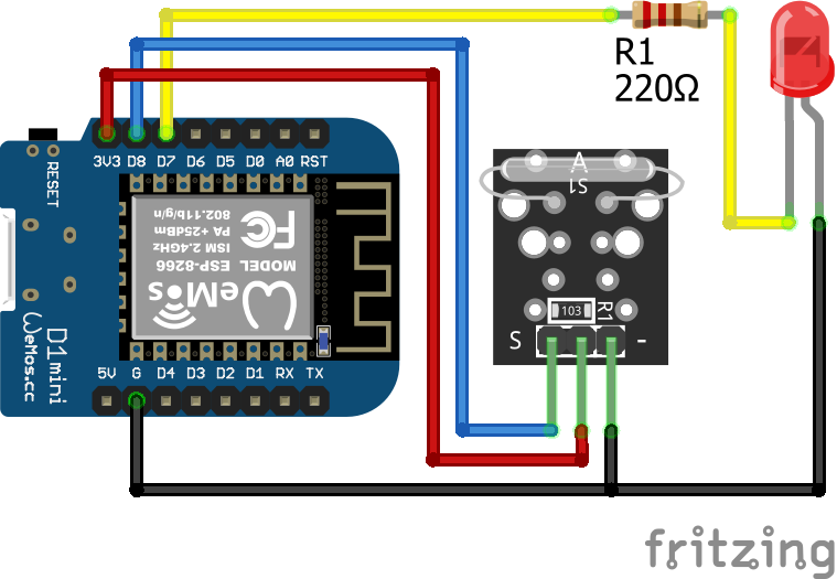
KY-025 ESP8266 WeMos D1 Mini
KY-021 Arduino Nano
KY-021 Arduino Pro Mini
KY-021 Arduino Uno
KY-021 Arduino Mega
KY-021 ESP32 NodeMCU
KY-021 ESP8266 NodeMCU
KY-021 ESP8266 WeMos D1 Mini
Leave A Comment