Sound Tutorial for Arduino, ESP8266 and ESP32
In this tutorial you learn everything you need to know about two different sound devices:
- Sound sensors which act like a microphone and are able to measure the volume of sounds. The Big Sound module and Small Sound module are part of this group.
- Buzzers or speakers which are able to output sounds. These devices are able to either output a sound which is generated by the microcontroller (passive) or generate the sound itself (active).
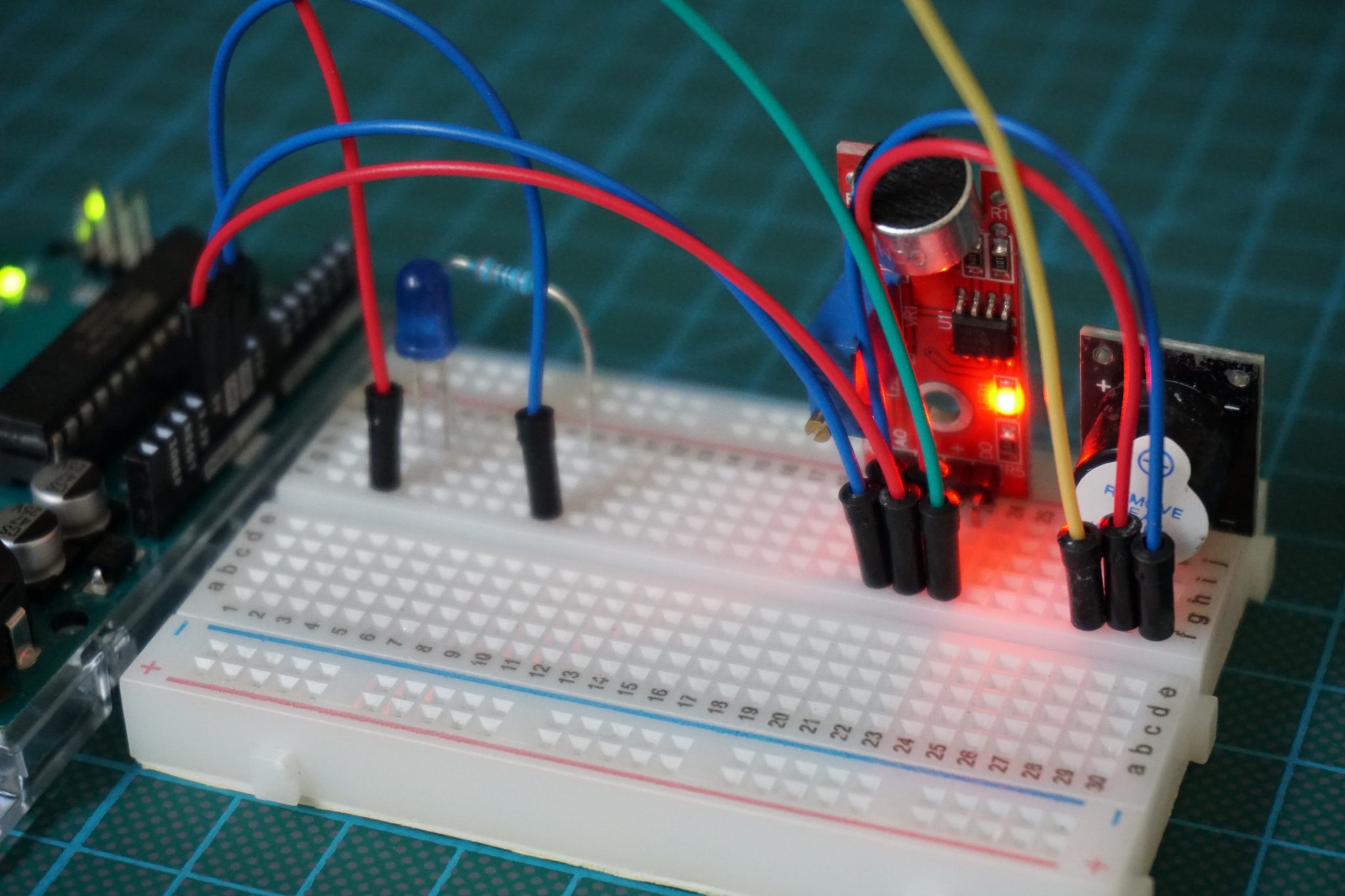
Table of Contents
Sound Sensor
| KY-038 | |
| Operation voltage | 3.3V…5V |
| Frequency response | 50Hz…20kHz |
| Impedance | 2.2 kΩ |
| Sensitivity | 48…66 dB |
The following table gives you an overview of all components and parts that I used for this tutorial. I get commissions for purchases made through links in this table.
| Arduino Uno | Amazon | Banggood | AliExpress | |
| OR | ESP8266 NodeMCU | Amazon | Banggood | AliExpress |
| OR | ESP32 NodeMCU | Amazon | Banggood | AliExpress |
| AND | Microphone Sound Module, Active Buzzer and Passive Buzzer are all part of a Sensor Pack | Amazon | Banggood | AliExpress |
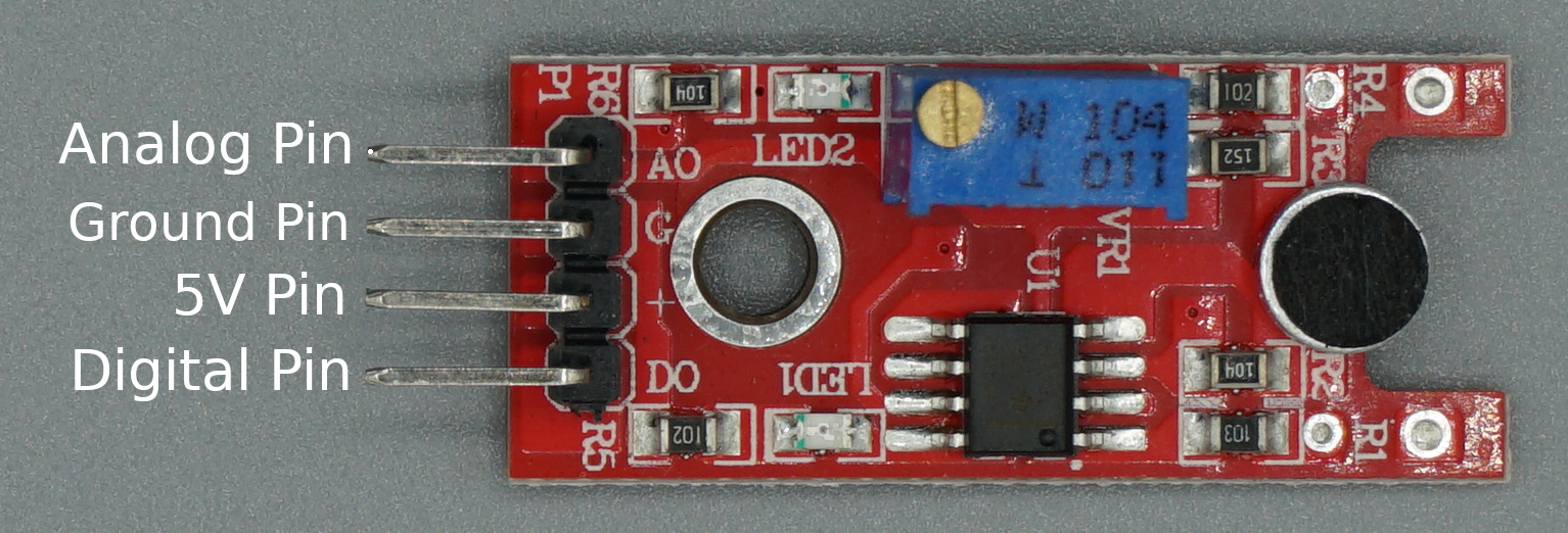
The following picture show the pinout of the sound sensor. You see that this sound sensor has 4 pins:
- Analog Pin to measure the exact analog value of the sound
- Ground Pin
- 5V Pin
- Digital Pin to only see is the threshold by the potentiometer is exeded.
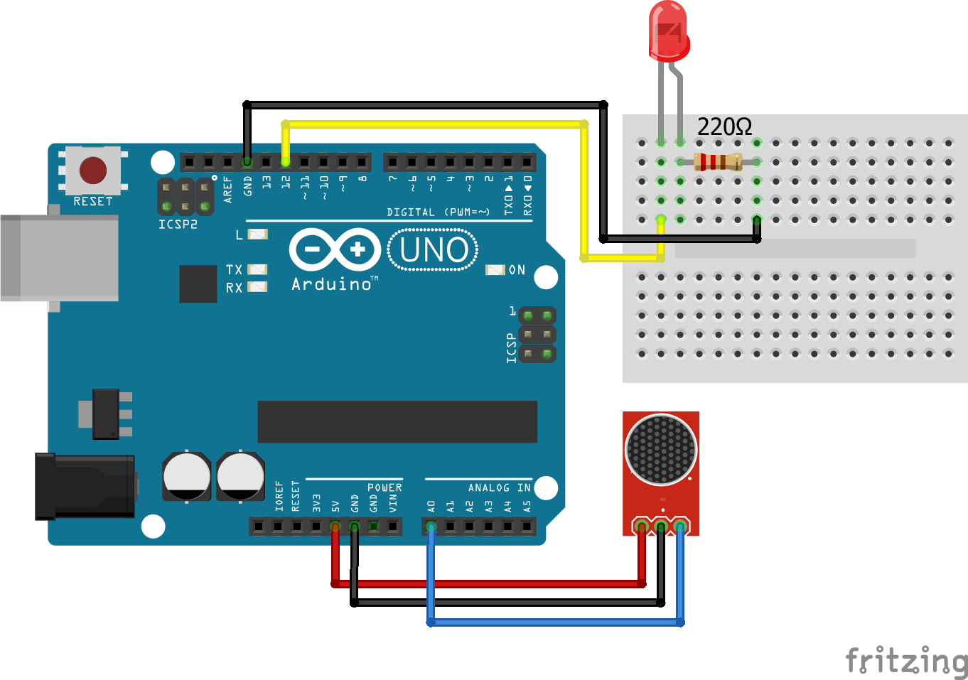
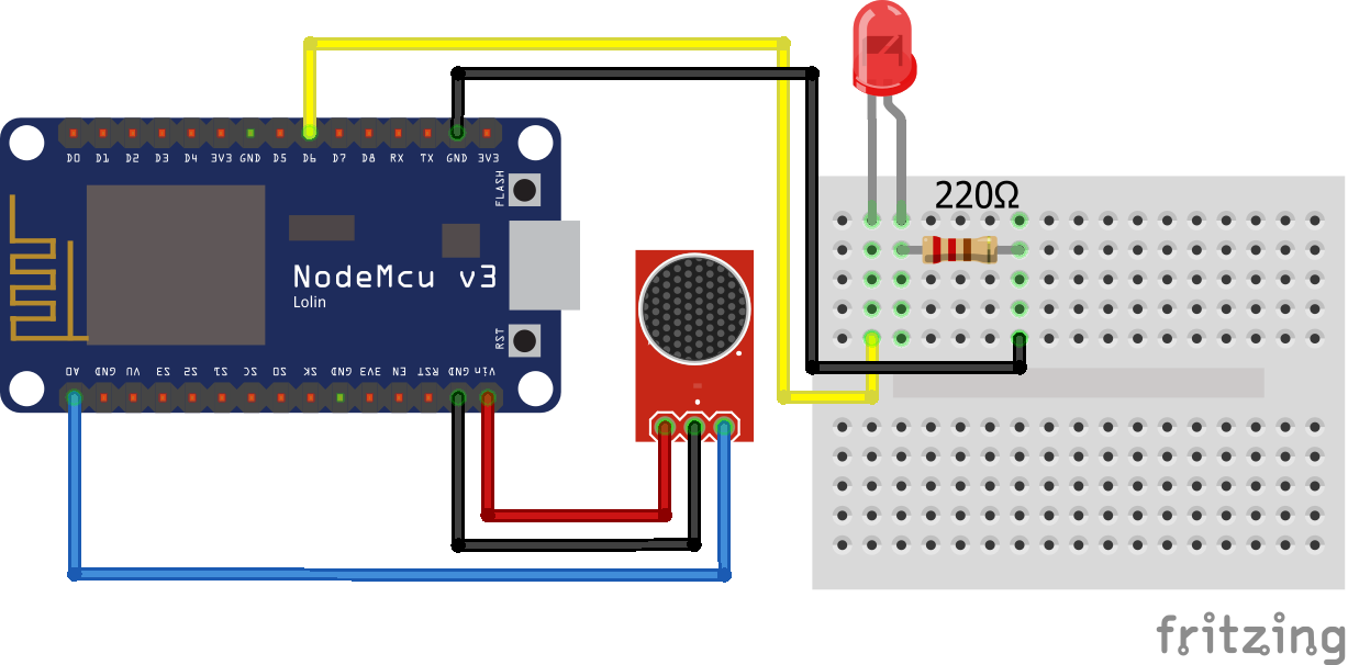
You will see in the following fritzing sketches only one picture of the sound sensor. But in reality I will either connect to analog pin or the digital pin to the microcontroller.
There are two main sound sensors as modules on the market: The Big Sound and Small Sound. Both are either purchasable as a single module or what I like to recommend is to buy these modules in a set, which is in sum cheaper.
The Small Sound module and the Big Sound module are similar. The only difference is the microphone, not only the size, but also the function. The large microphone module has an electronic microphone, and the small microphone module just has a normal microphone. Therefore the electronic microphone has more high sensitivity, but they share the same work method.
If you want to use a sound sensor in your project besides from little differences in the datasheet, you can use the sound sensor you have. There is no need to extra buy the Big Sound Sensor.
The Big and the Small Sound sensor have a potentiometer build in on the module. With this potentiometer you can control the sensitivity of the sensor, because you might have a use case where the normal surrounding noise should not be detected by the sound sensor.
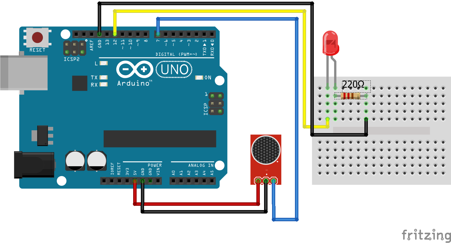
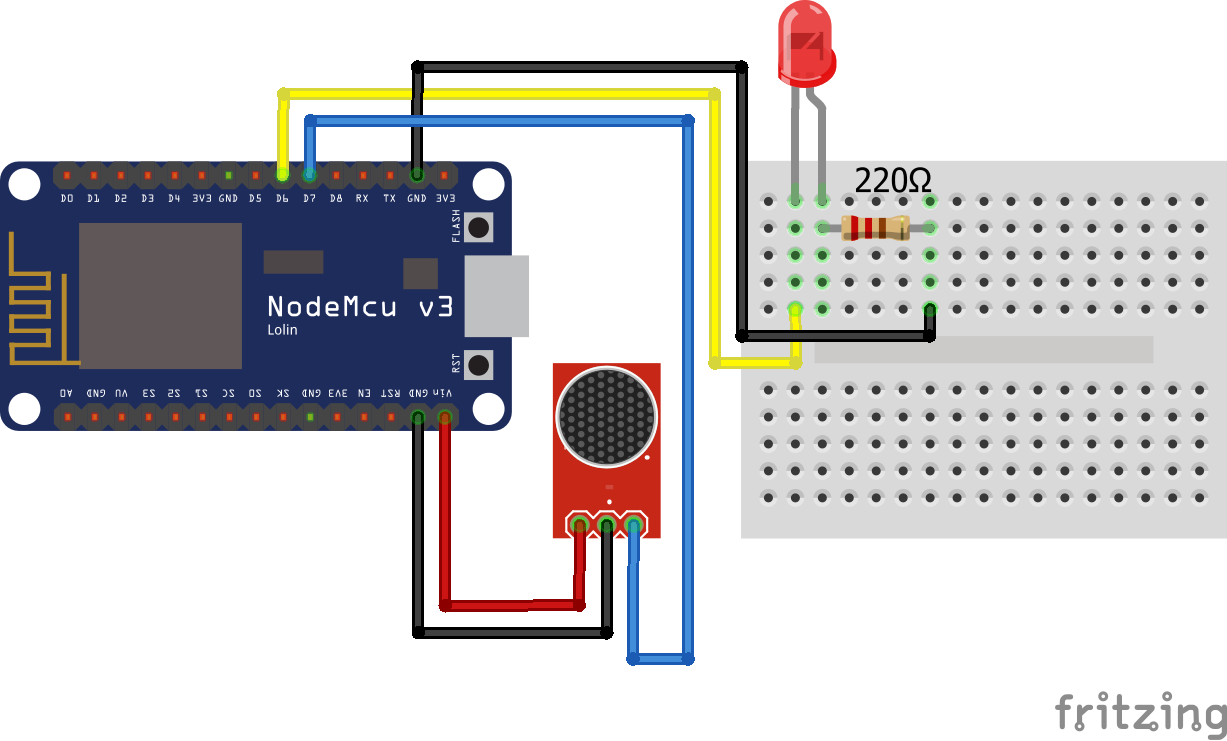
Now let us connect the sound sensors to the Arduino or ESP8266 based board. I will use an Arduino Uno and a NodeMCU V2 board for the following examples.
For the following example I want to clap in my hand and if a threshold was reached, a LED should turn on for 3 seconds.
Because the output of the sensor can be analog or digital, we will cover both possibilities and have therefore two different fritzing sketches per microcontroller. It is also possible to combine the analog and the digital output. We do not cover this possibility in this tutorial but I am sure you are able to combine the two examples.
Sound Sensor with Analog Input
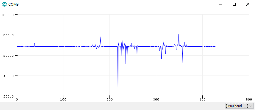
For the analog input we have to connect the signal pin from the sound sensor to the analog pin from the microcontroller. The microcontroller read the analog values. The maximum ADC reference voltage is defined to 5V = 1023 which gives us the best resolution because the maximum operation voltage of the sound sensors are also 5V.
int Led = 12 ;    // define LED Interface
int Sound = A0;    // define Sound Interface
int val = 0;      // define numeric variables val

void setup ()
{
  Serial.begin(9600);
  pinMode (Led, OUTPUT) ;   // define LED as output interface
  pinMode (Sound, INPUT) ;  // define Sound sensor as input interface
}
void loop ()
{
  val = analogRead(Sound);
  Serial.println(val,DEC);//print the sound value to serial
  delay(100);
}
Sound Sensor with Digital Input
For the digital input connection we connect the signal pin with a digital input pin of the microcontroller. Because the signal is digital and only gives us a 0 or 1, we have to make sure that the sensitivity of the sensor is well calibrated with the potentiometer.
int Led = 12 ;    // define LED Interface
int Sound = 7;    // define Sound Interface
int val = 0;      // define numeric variables val

void setup ()
{
  pinMode (Led, OUTPUT) ;       // define LED as output interface
  pinMode (Sound, INPUT) ;  // define Sound sensor as input interface
}
void loop ()
{
  val = digitalRead(Sound);//
  if (val == HIGH) //
  {
    digitalWrite (Led, HIGH);
    delay(3000);
    }
  else
  {
    digitalWrite (Led, LOW);
    }
}
Buzzer and Speaker
Now that we know how to measure sounds with sound sensors, we can care about how to generate sounds. There are 3 main classes of buzzers and speakers.
- Active Buzzers: Active buzzers are able to generate the sound itself.
- Passive Buzzers: Passive buzzers are devices are able to output a sound which is generated by the microcontroller.
- Speakers
In the following chapters we will drive deeper into the different buzzers and speakers. Also we create an example where we create some cool music (Active Buzzer) and an alarm signal, when pressing a button (Passive Buzzer).
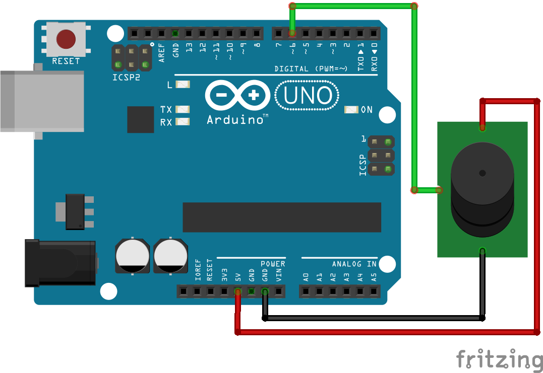
Active Buzzers
You can simply turn an active buzzer on and off with a digital pin from the microcontroller as you would control an LED. The sound from an active buzzer is more like an alarm sound because you cannot control the frequency. Be aware that most active buzzers require a bit more current. So it could be possible that a MOSFET is needed to boost the current / voltage.

int Buzzer = 6 ;  // define Buzzer Interface

void setup ()
{
  pinMode (Buzzer, OUTPUT) ;    // define Button as output interface
}
void loop ()
{
  digitalWrite (Buzzer, HIGH) ; //send tone
  delay(1000);
  digitalWrite (Buzzer, LOW) ;  //no tone
  delay(1000);
}
Passive Buzzers
Because unlikely the passive buzzers do not create the sound itself, the passive buzzers need and AC “sound signal” created by the microcontroller. The advantage is that it is possible to play music because you can control the volume/pitch. The only downside is, that the microcontroller needs extra processing time to crate the music. This could be an issue for a projects where the runtime is very important. In this example we play a cool song. Do you know it? If so use comment the song below in the comment section 🙂
const int c = 261;
const int d = 294;
const int e = 329;
const int f = 349;
const int g = 391;
const int gS = 415;
const int a = 440;
const int aS = 455;
const int b = 466;
const int cH = 523;
const int cSH = 554;
const int dH = 587;
const int dSH = 622;
const int eH = 659;
const int fH = 698;
const int fSH = 740;
const int gH = 784;
const int gSH = 830;
const int aH = 880;

const int buzzerPin = 6;
int counter = 0;

void setup()
{
  //Setup pin modes
  pinMode(buzzerPin, OUTPUT);
}

void loop()
{

  //Play first section
  firstSection();

  //Play second section
  secondSection();

  //Variant 1
  beep(f, 250);
  beep(gS, 500);
  beep(f, 350);
  beep(a, 125);
  beep(cH, 500);
  beep(a, 375);
  beep(cH, 125);
  beep(eH, 650);

  delay(500);

  //Repeat second section
  secondSection();

  //Variant 2
  beep(f, 250);
  beep(gS, 500);
  beep(f, 375);
  beep(cH, 125);
  beep(a, 500);
  beep(f, 375);
  beep(cH, 125);
  beep(a, 650);

  delay(650);
}

void beep(int note, int duration)
{
  //Play tone on buzzerPin
  tone(buzzerPin, note, duration);

  //Play different LED depending on value of 'counter'
  if(counter % 2 == 0)
  {
    delay(duration);
  }else
  {
    delay(duration);
  }

  //Stop tone on buzzerPin
  noTone(buzzerPin);

  delay(50);

  //Increment counter
  counter++;
}

void firstSection()
{
  beep(a, 500);
  beep(a, 500);
  beep(a, 500);
  beep(f, 350);
  beep(cH, 150);
  beep(a, 500);
  beep(f, 350);
  beep(cH, 150);
  beep(a, 650);

  delay(500);

  beep(eH, 500);
  beep(eH, 500);
  beep(eH, 500);
  beep(fH, 350);
  beep(cH, 150);
  beep(gS, 500);
  beep(f, 350);
  beep(cH, 150);
  beep(a, 650);

  delay(500);
}

void secondSection()
{
  beep(aH, 500);
  beep(a, 300);
  beep(a, 150);
  beep(aH, 500);
  beep(gSH, 325);
  beep(gH, 175);
  beep(fSH, 125);
  beep(fH, 125);
  beep(fSH, 250);

  delay(325);

  beep(aS, 250);
  beep(dSH, 500);
  beep(dH, 325);
  beep(cSH, 175);
  beep(cH, 125);
  beep(b, 125);
  beep(cH, 250);

  delay(350);
}
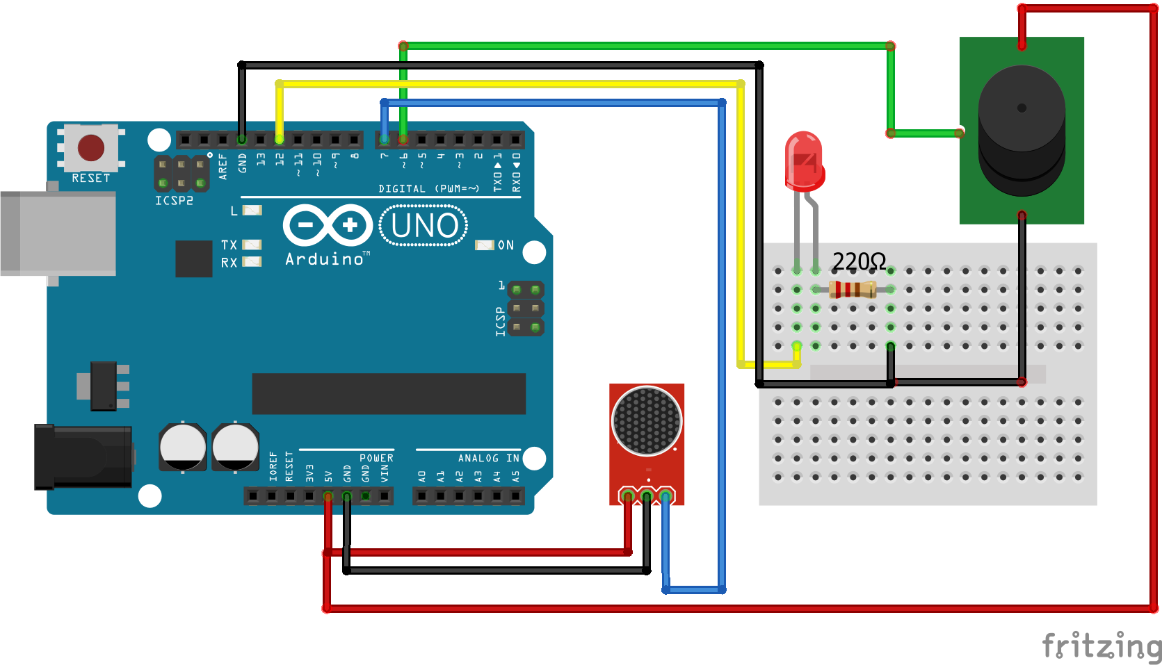
Lets put it all together. We learned how we can measure sounds and how we can produce sounds. The following example will turn on an active buzzer and an LED when the Big Sound measures a clap from me.
int Led = 12 ;    // define LED Interface
int Buzzer = 6 ;  // define Buzzer Interface
int Sound = 7;    // define Sound Interface
int val = 0;      // define numeric variables val

void setup ()
{
  pinMode (Led, OUTPUT) ;       // define LED as output interface
  pinMode (Buzzer, OUTPUT) ;    // define Button as output interface
  pinMode (Sound, INPUT) ;  // define Sound sensor as input interface
}
void loop ()
{
  val = digitalRead(Sound);//
  if (val == HIGH) //
  {
    digitalWrite (Led, HIGH);
    digitalWrite (Buzzer, HIGH) ; //send tone
    delay(3000);
    digitalWrite (Buzzer, LOW) ;  //no tone
    }
  else
  {
    digitalWrite (Led, LOW);
    }
}
If you have any questions regarding sounds please use the comment section below and I will answer your question as soon as possible.
Leave A Comment