KY-026 Flame Sensor Tutorial for Arduino, ESP8266 and ESP32
In this article you learn how to build your own fire alarm that could detect a fire inside a room.
In the first part of the tutorial you learn the different methods to detect a fire.
We finish the tutorial with a project where we build a fire alarm based on the KY-026 flame sensor module and an active buzzer.
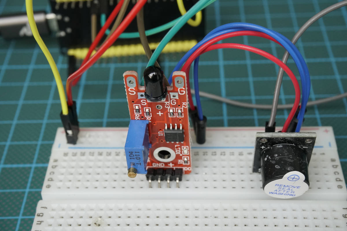
Table of Contents
How to Detect a Fire with a Flame Sensor for Microcontroller?
A fire or flame sensor detects if there is a present fire or not. Generally the optical detection is the fastest way to detect a fire. Therefore we will concentrate on sensors with optical detection.
During a fire, photons with different wavelength are emitted. The following table shows the different wavebands, their wavelength and the corresponding flame detection methods.
| Wavebands | Wavelength | Flame Detection Methods |
|---|---|---|
| Ultraviolet (UV) | < 0.3μm | Ultraviolet Detector |
| Visible (Vis) | 0.7μm – 1.1μm | Near IR Array Detector |
| Infrared (IR) | > 1.1μm | IR Detector |
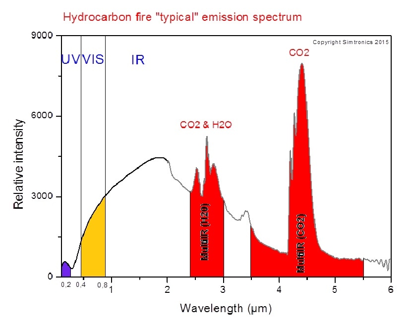
What flame detection method you use for a fire alarm depends on the environmental conditions, but the relative intensity of photons in the waveband is a good indication. The following picture shows the typical emission spectrum of a hydrocarbon fire along with the 3 wavebands.
In the following three sub-chapters we discuss every waveband with the corresponding flame detection method and finally choose our flame sensor that we use for the fire alarm.
Flame Sensor based on a Ultraviolet Detector
The ultraviolet waveband has a wavelength shorter than 0.3μm and is not visible for the human eyes. To detect a fire, the ultraviolet detector recognizes the UV radiation emitted at the instant of a fire ignition. The sensor has a very fast reaction time with 3-4 milliseconds but due to the fast reaction time, you have to add a delay of a couple seconds to minimize false alarms. False alarms are caused by other UV sources like lighting and sunlight.
Flame Sensor based on Near IR Array Detector
In the visible wavebands between 0.7μm – 1.1μm, it is possible to use flame recognition technology to confirm a fire. The recognition system analyzes near IR radiation with multiple channel or pixel arrays to create a picture or video of the flames. In combination with digital image processing and video analysis, the Near IR Array Detector is the most reliable technology to detect a fire.
Flame Sensor based on IR Detector
The next higher wavelength with 1.1μm and greater are in the infrared waveband. There are specialized fire-fighting thermal imaging cameras (TIC) that detect a fire based on specific patterns giving off by hot gases. From the hydrocarbon fire emission spectrum, you see that the resonance frequency of CO2 is between 4.3μm – 4.4μm. This wavelength has a very high intensity due to the CO2 that is released during a fire, and is therefore very good to detect a fire.
But also the IR detector can have false alarms that are caused by hot surfaces, thermal radiation in the background, water on the detector lens or exposure to direct sunlight.
Overview of the KY-026 Flame Sensor Module
Before we start using the flame sensor module, we have to know how the sensor itself and the whole module with all other electronic components is working. Therefore we start with the technical datasheet of the whole module before we take a closer look at the pinout of the KY-026 flame sensor module.
In this tutorial I build a fire alarm based on the KY-026 flame sensor module. The module contains a YG1006 infrared diode, a highly sensitive NPN silicon phototransistor. Due to its black epoxy, the sensor is sensitive to infrared radiation.
KY-026 Flame Sensor Module Technical Datasheet
The following table shows the technical datasheet for the KY-026 flame sensor module.
| Operation Voltage | 3.3V...5V |
| Infrared Radiation Sensitivity | 0.76μm...1.1μm |
| Peak Wavelength | 0.94μm |
| Detection Angle | 0°...60° |
The KY-026 fire sensor module has an operation voltage between 3.3V and 5V and is therefore suitable for Arduino, ESP8266 and ESP32 microcontroller.
The build in YG1006 infrared diode is sensitive to infrared radiation between 0.76μm and 1.1μm. When fire burns, small amounts of infrared light are emitted. This light is received by the photodiode (IR receiver) on the sensor module.
The detection angle of the phototransistor is between 0 and 60 degree. Therefore a fire is detected in a large angle around the sensor.
KY-026 Flame Sensor Module Pinout and Electronic Components
The following picture shows the KY-026 flame sensor breakout board with the pinout and all electronic components. You can click on the image to enlarge it.
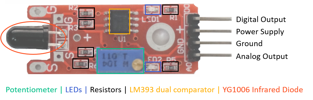
The KY-026 flame sensor module consists of the following electronic parts:
- 4 output pins that connect the KY-026 flame sensor module to a microcontroller.
- A0: Analog pin to transfer an analog signal.
- GND: Ground to connect the flame sensor to ground with the microcontroller.
- +: Pin for the 3.3V or 5V operation voltage regarding to the technical datasheet.
- D0: Digital output based on a predefined threshold through the potentiometer and the operation voltage of the microcontroller.
- Potentiometer to define a threshold for the digital output pin.
- 2 LEDs to indicate that the module is operating (LED1) and to indicate the status of the digital pin (LED2).
- 6 Resistors to prevent LEDs for too high voltages and to operate as voltage dividers.
- LM393 dual comparator to compare the signal created by the infrared diode with the predefined value through the potentiometer and to control the status of the LED that indicates the status of the digital output.
- YG1006 Infrared Diode to recognize flames around the sensor module.
Schematic of the KY-026 Flame Sensor Module
To understand how the KY-026 flame sensor module is working and how the analog and digital output changes when the sensor recognizes a fire, we must look at the schematic of the sensor module.
The schematic of the KY-026 flame sensor module in the following picture shows us how all electronic parts of the module are connected.
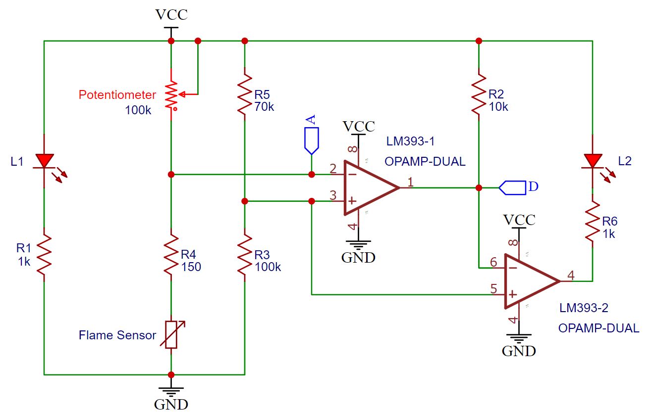
On the left side we see LED1 in series with resistor R1 (1kΩ) to indicate that the KY-026 flame sensor module has a valid power supply.
The “second column” between the operation voltage and ground consists of the potentiometer, the resistor R4 (150Ω) and the YG1006 infrared diode as flame sensor, represented by a variable resistance. The resistors build a voltage divider that is connected with the reverence voltage of the LM393 dual comparator (2). The potential on this voltage divider is also the analog output of the KY-026 sensor module.
The second voltage divider is built with resistor R5 (70kΩ) and resistor R3 (100kΩ). The voltage divider is the input voltage of both comparators (3) (5).
The output of the first comparator of the LM393 (1) is connected to the digital output of the KY-026 flame sensor module and to resistor R2 (10kΩ) that disconnects the digital output from the operation voltage. Otherwise the digital output would be equal to the operation voltage independent of the status of the flame sensor. The reference voltage of the second comparator (6) is also the output of the first comparator (1).
The output of the second LM393 comparator (4) closes the circuit of the second LED2 and resistor R6 (1kΩ).

Microcontroller Datasheet eBook
The 35 pages Microcontroller Datasheet Playbook contains the most useful information of 14 Arduino, ESP8266 and ESP32 microcontroller boards.
Functionality of the KY-026 Flame Sensor Module
After we already know the schematic of the KY-026 flame sensor module, the understanding of the functionality is not complex.
If there is an operation voltage between 3.3V and 5V, connected to the KY-026 module, LED1 turns on and the voltage divider between R5 and R3 creates a stable voltage of V = VCC * R3 / (R3+R5) = VCC * 100/170 = 0.6*VCC.
This voltage is the input voltage of the first (3) and second (5) comparator.
The other voltage divider created by the potentiometer and the resistor R4 in series to the YG1006 infrared diode is the input voltage of the first comparator (2) and also the analog output of the KY-026 flame sensor module. The potential on the analog output depends on the resistance of the potentiometer and the voltage drop over the infrared diode.
The voltage drop over the infrared diode depends on the infrared radiation and is
- lower if there is a flame detected -> lower analog output
- higher if there is no flame detected -> higher analog output
The potentiometer has to be adjusted that if there is a flame detected, the electrical potential on the analog output and therefore the reference voltage of the first comparator (2) is lower than the input voltage 0.6*VCC. In this case, the output (1) of the first comparator of the LM393 is VCC (HIGH) and therefore the digital output of the KY-026 flame sensor module. Because VCC (6) > 0.6*VCC (5), the output of the second comparator (4) is GND (LOW). Now there is a potential difference between the LED2 and resistor R6 and the output of the second comparator (4), that turns LED2 on.
If there is no flame detected, the potential on the analog output must be higher than the reference voltage to set the output of the first comparator (1) to GND (LOW). In this case the digital output is GND and the input voltage of the second comparator 0.6*VCC (5) is greater than the reference voltage GND (6). The output of the second comparator (4) is VCC and because there is no potential difference over the resistor R6 and LED2, LED2 is off.
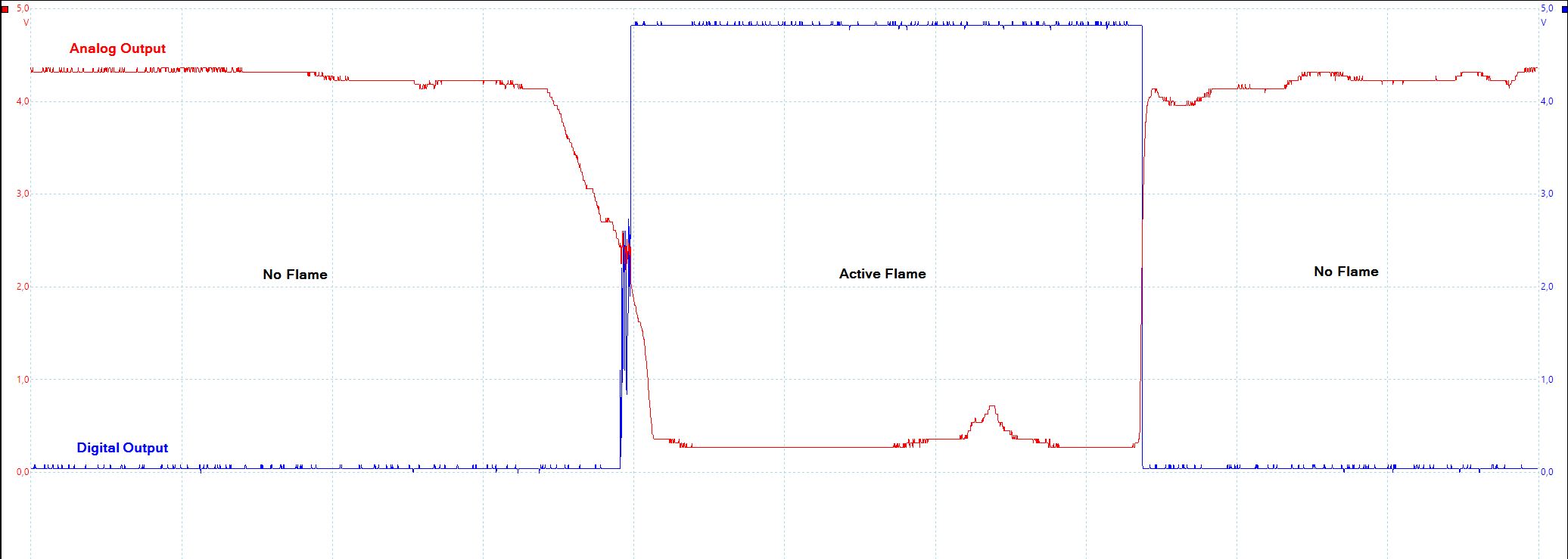
The relationship of the analog and digital output of the KY-026 flame sensor module is also shown in the following picture, where I measured the analog and digital output of the flame sensor module with my oscilloscope. Click on the image to enlarge it.
Summarized Functionality of the KY-026 Flame Sensor Module
| Active Flame? | Infrared Radiation | Analog Output | Digital Output | LED1 |
|---|---|---|---|---|
| Yes | High | Low Value | VCC (HIGH) | On |
| No | Low | High Value | GND (LOW) | Off |
- If the measured infrared radiation increases due to a detected flame, the analog output decreases.
- To increase or decrease the sensitivity of the digital output of the KY-026 flame sensor module, adjust the potentiometer.
- If the threshold of the potentiometer is not exceeded, the digital output is HIGH and LED1 is on.
- If there is no flame and therefore no infrared radiation, the threshold of the potentiometer is exceeded, the digital output is LOW and LED1 is off.
The following table gives you an overview of all components and parts that I used for this tutorial. I get commissions for purchases made through links in this table.
| Component | Amazon Link | AliExpress Link |
|---|---|---|
| Arduino Nano | Amazon | AliExpress |
| Arduino Pro Mini | Amazon | AliExpress |
| Arduino Uno | Amazon | AliExpress |
| Arduino Mega | Amazon | AliExpress |
| ESP32 ESP-WROOM-32 | Amazon | AliExpress |
| ESP8266 NodeMCU | Amazon | AliExpress |
| ESP8266 WeMos D1 Mini | Amazon | AliExpress |
| Flame Sensor in Sensor Kit | Amazon | AliExpress |
| Active Buzzer in Sensor Kit | Amazon | AliExpress |
Wiring between the Flame Sensor Module and Microcontroller
The following pictures show how to connect the flame sensor to different microcontroller boards. I also added an active buzzer to the project that makes a sound if there is an active fire. If you are interested in more details about active or passive buzzers, visit the buzzer tutorial.
If your favorite board is missing, use the comment section below and I will add your board to this article. Also you can click on each picture to enlarge it to see the connection in detail.
Wiring between KY-026 Flame Sensor Module and Arduino Boards
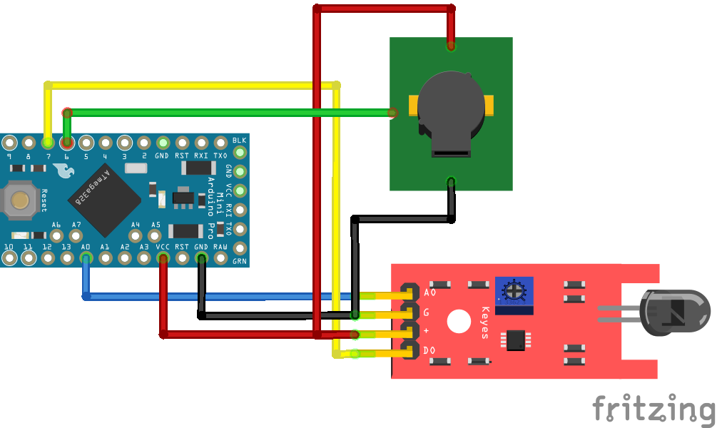
The operation voltage of the KY-026 flame sensor module is between 3.3V and 5V. Because the most Arduino microcontroller have an operation voltage of 5V, you can connect the fire sensor direct to the 5V of the Arduino microcontroller board. The following pictures show the wiring between different Arduino microcontroller, the KY-026 fire sensor and the active buzzer.
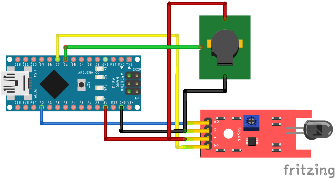
For more information about the Arduino Nano, visit the Arduino Nano Tutorial.
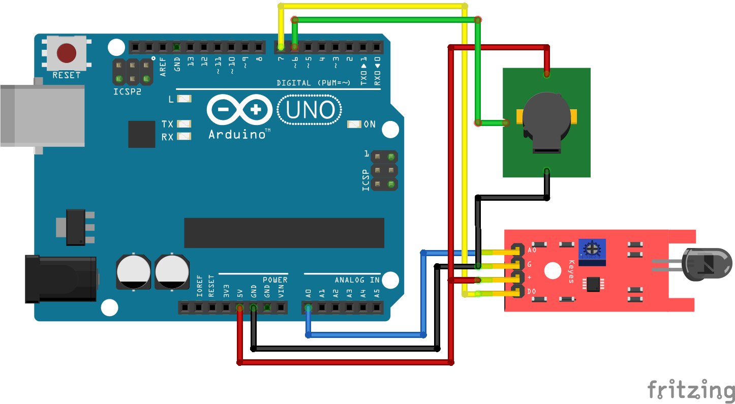
For more information about the Arduino Uno, visit the Arduino Uno Tutorial.
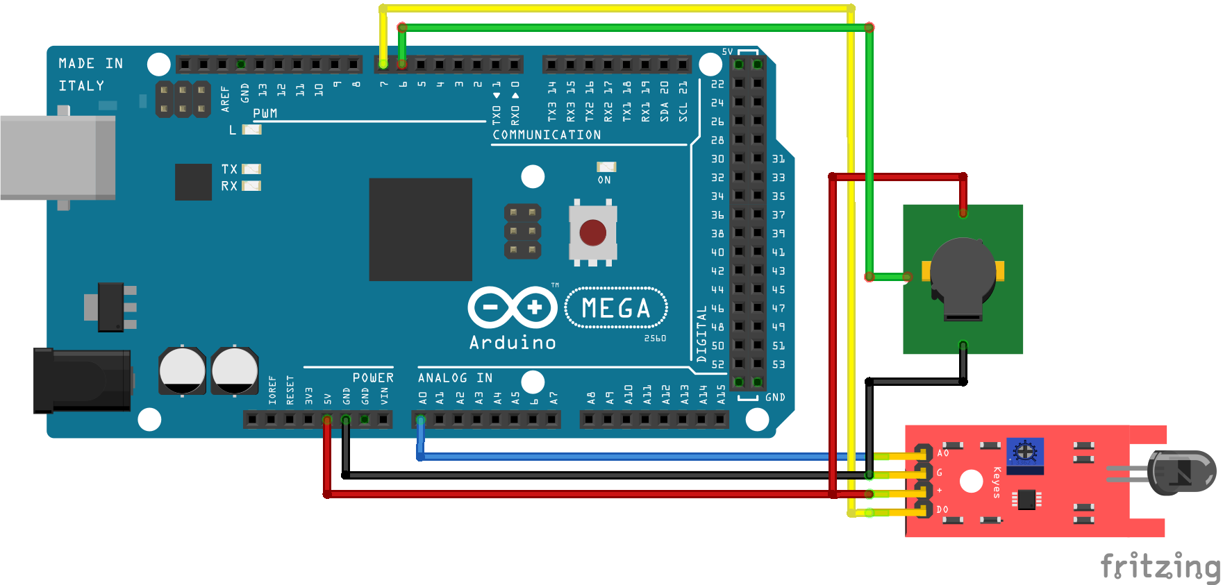
For more information about the Arduino Mega, visit the Arduino Mega Tutorial.
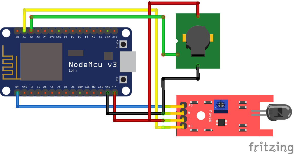
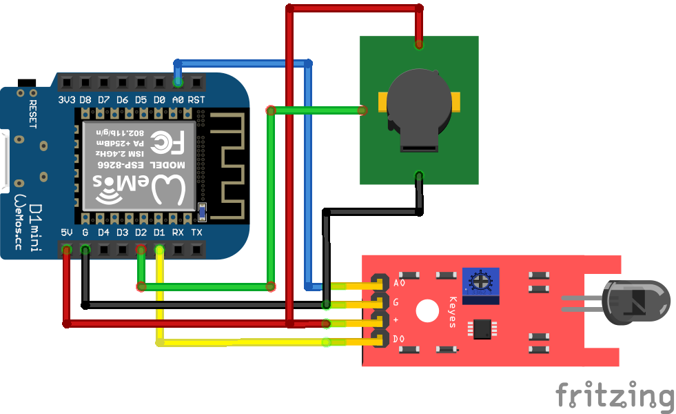
Wiring between KY-026 Flame Sensor Module and ESP8266 Boards
Because the KY-026 fire sensor also works with an operation voltage of 3.3V, the sensor module can be used in combination with the ESP8266 microcontroller that has an operation voltage of 3.3V. The following pictures show the wiring between the KY-026 fire sensor module, the active buzzer and the ESP8266 microcontroller NodeMCU and WeMos D1 Mini.
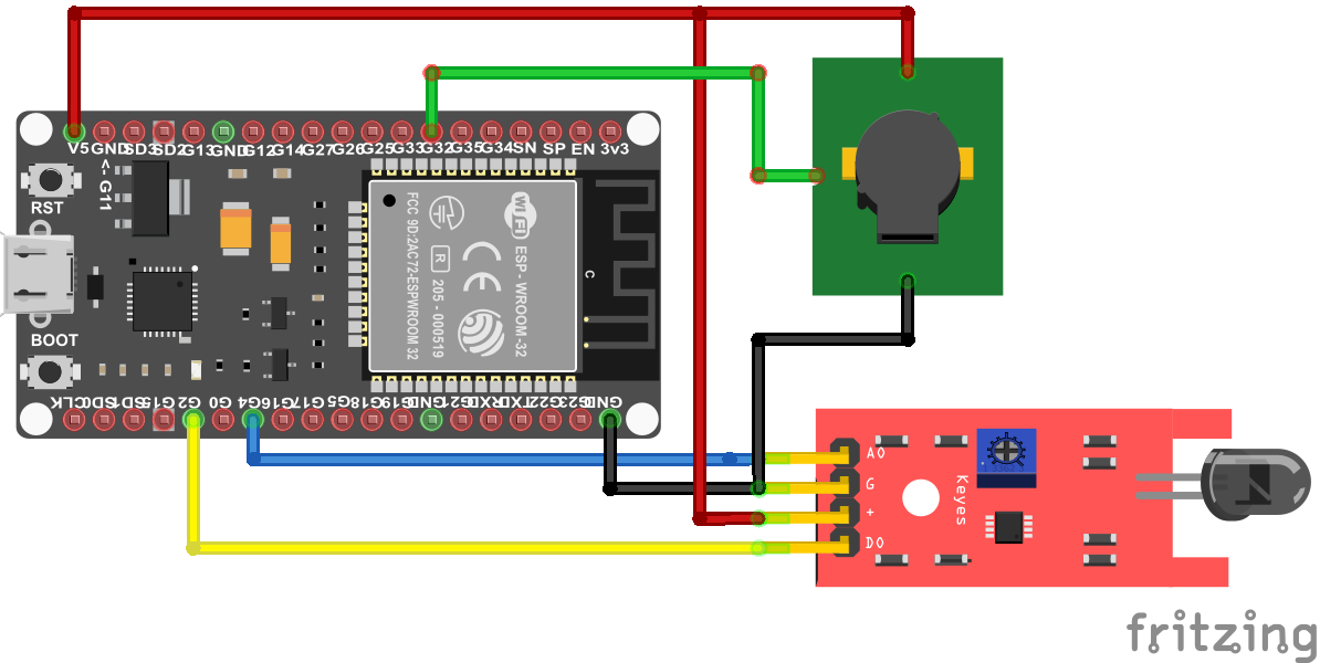
Wiring between KY-026 Flame Sensor Module and ESP32 Boards
Like the ESP8266, the ESP32 has an operation voltage of 3.3V and can be used in combination with the ESP32 microcontroller. The following picture shows the wiring between the ESP32 ESP-WROOM-32, the KY-026 fire sensor module and the active buzzer.
Program Code to Detect a Fire with KY-026 Flame Sensor
From the wiring between the fire sensor and the different Arduino, ESP8266 and ESP32 microcontroller, you see that I use different pins. Therefore we have to take care that the right pins are used in the program code, that you see in the following section.
int Buzzer = 6;        // used for Arduino
int Fire_analog = A0;    // used for Arduino
int Fire_digital = 7;   // used for Arduino

//int Buzzer = D2;        // used for ESP8266
//int Fire_analog = A0;    // used for ESP8266
//int Fire_digital = D1;   // used for ESP8266

//int Buzzer = 32;        // used for ESP32
//int Fire_analog = 4;    // used for ESP32
//int Fire_digital = 2;   // used for ESP32

void setup() {
  Serial.begin(115200);
  pinMode(Buzzer, OUTPUT);
  pinMode(Fire_digital, INPUT);
}

void loop() {
  int firesensorAnalog = analogRead(Fire_analog);
  int firesensorDigital = digitalRead(Fire_digital);

  Serial.print("Fire Sensor: ");
  Serial.print(firesensorAnalog);
  Serial.print("\t");
  Serial.print("Fire Class: ");
  Serial.print(firesensorDigital);
  Serial.print("\t");
  Serial.print("\t");

  if (firesensorAnalog < 1000) {
    Serial.println("Fire");
    digitalWrite (Buzzer, HIGH) ; //send tone
    delay(1000);
    digitalWrite (Buzzer, LOW) ;  //no tone
  }
  else {
    Serial.println("No Fire");
  }
  delay(100);
}
In the first part of the program code, we have to define the connected pins. If you copy the script, it is commented in the way that it runs with Arduino boards. If you want to use ESP8266 or ESP32 boards, you have to comment the three Arduino lines and uncomment the lines for your microcontroller that you want to use.
The three pins that we define are the following
| Pin | Arduino | ESP8266 | ESP32 |
|---|---|---|---|
| Digital pin to active buzzer | 6 | D2 | 32 |
| Analog pin of fire sensor | A0 | A0 | 4 |
| Digital pin of fire sensor | 7 | D1 | 0 |
Because the ESP32 has build-in analog to digital converter, you can use multiple pins as analog input. The pins that you can use as analog pins are described in the ESP32 pinout tutorial or I recommend to download my Microcontroller Datasheet eBook.
In the setup function, we set the baud rate to 115200, that have to match to the baud rate at the serial monitor in the Arduino IDE. Also we define the digital pin that connects the buzzer as output because we want to activate and deactivate the buzzer in case of a fire. Also we set the digital connection of the fire sensors output as input of the Arduino, ESP8266 or ESP32 microcontroller, because we want to read the digital value.
In the loop function, we first read the analog and digital value of the flame sensor and print both values to the serial interface. To separate each value in the serial monitor, we use the tab function \t.
Now we have to define if there is a fire or not. This decision can be made based on two values:
- The analog value of the fire sensor
- The digital value of the fire sensor
My suggestion is always to choose the analog value because in most cases it is easier to change the threshold in software, compared to the adjustable LM393 comparator that outputs the digital value.
For this definition, I set the threshold to 1000 and lower for the analog value of the flame sensor. For the initial build you can also use the threshold of 1000 but maybe you have to play around with the potentiometer and different thresholds to get a stable operation point for your fire sensor.
For the fire sensor, lower values mean a higher infrared light emitted from a fire. If the analog value of the fire sensor is lower than 1000, we print in the serial monitor that there is a fire and set the buzzer high. When the active buzzer is activated we wait for 1 second and turn the buzzer off. If the analog value is higher or equal 1000, we print that there is no fire.
At the end of the program code we wait for 100 milliseconds and start the loop function all over.
The following video shows the fire sensor in action. The fire is detected and you hear the buzzer.

I hope you enjoyed reading my tutorial about the KY-026 flame sensor module. You can also add a MQ-2 gas sensor to the fire alarm to detect smoke in case of a fire. In the MQ-2 gas sensor tutorial you learn how to add the gas sensor to your project.
If you have any questions regarding this article, use the following comment section to ask your questions. I will answer them as soon as possible.
