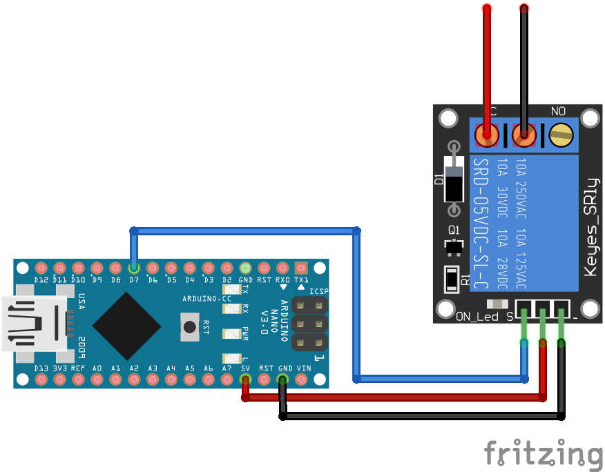
Relais Module Arduino Nano
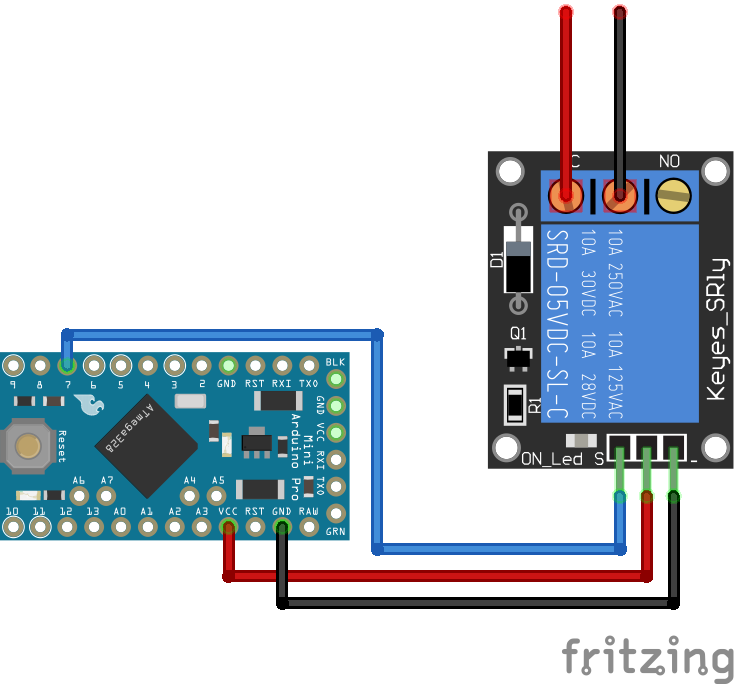
Relais Module Arduino Pro Mini
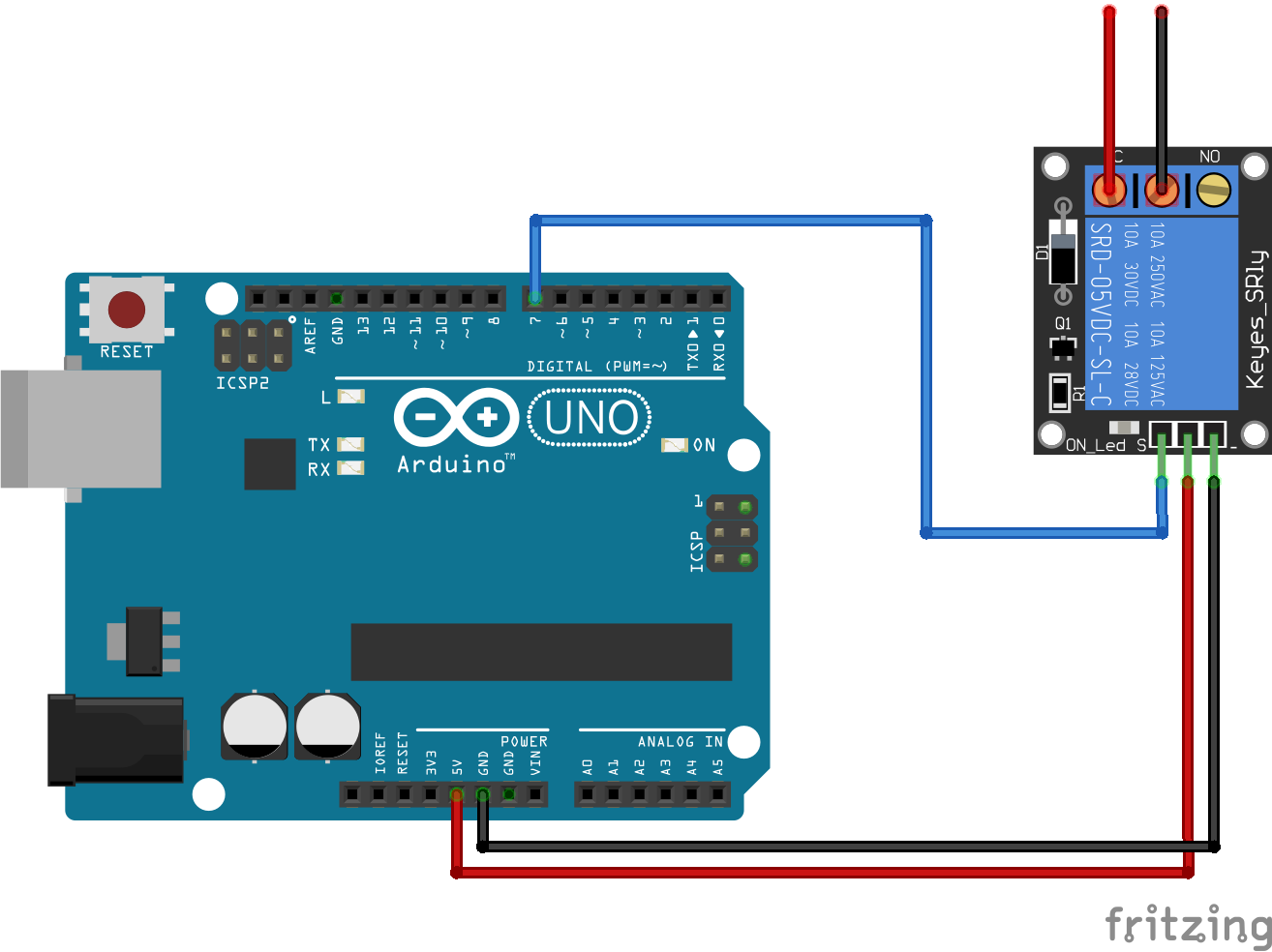
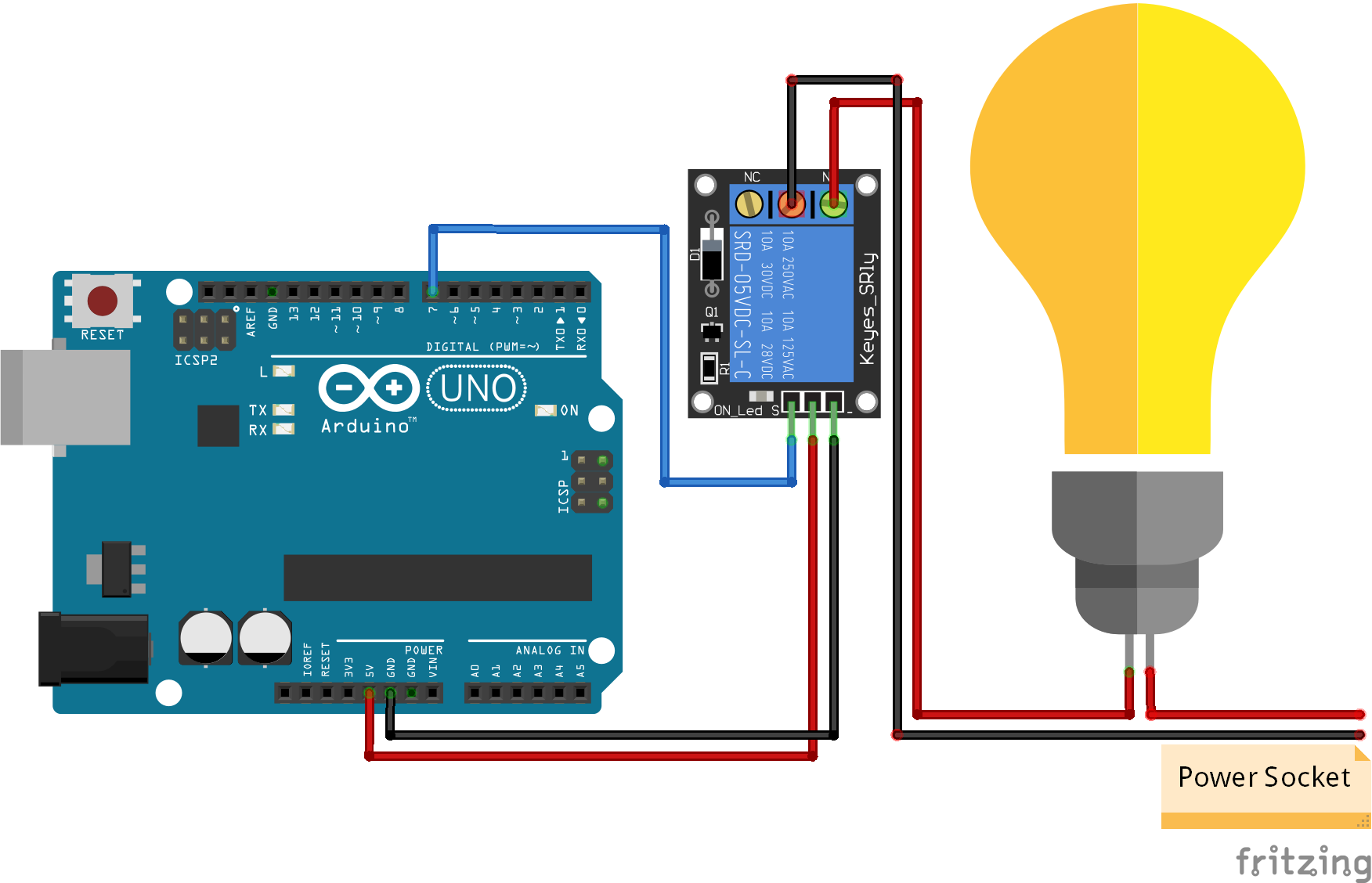
Relais Module Arduino Uno
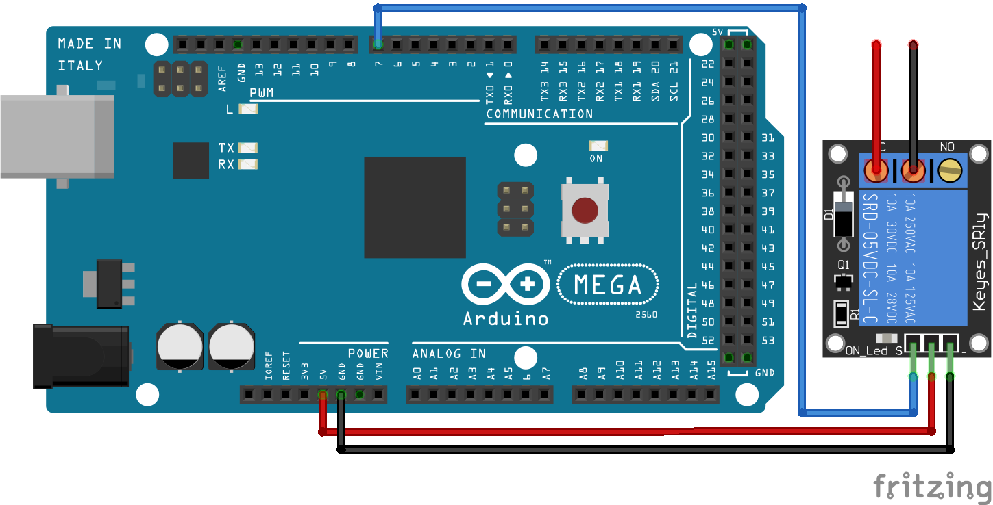
Relais Module Arduino Mega
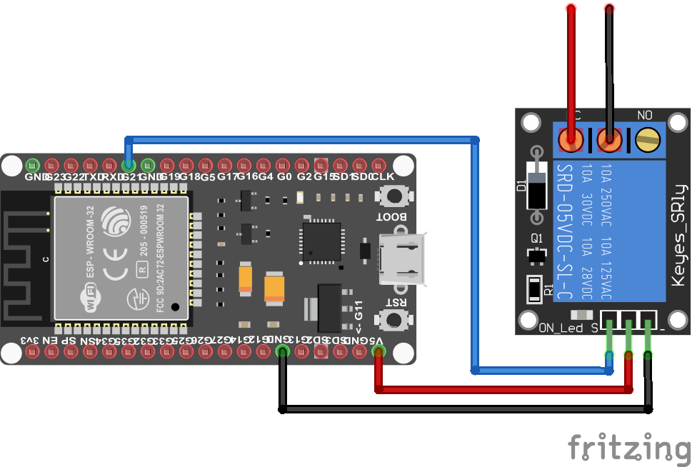
Relais Module ESP32 NodeMCU
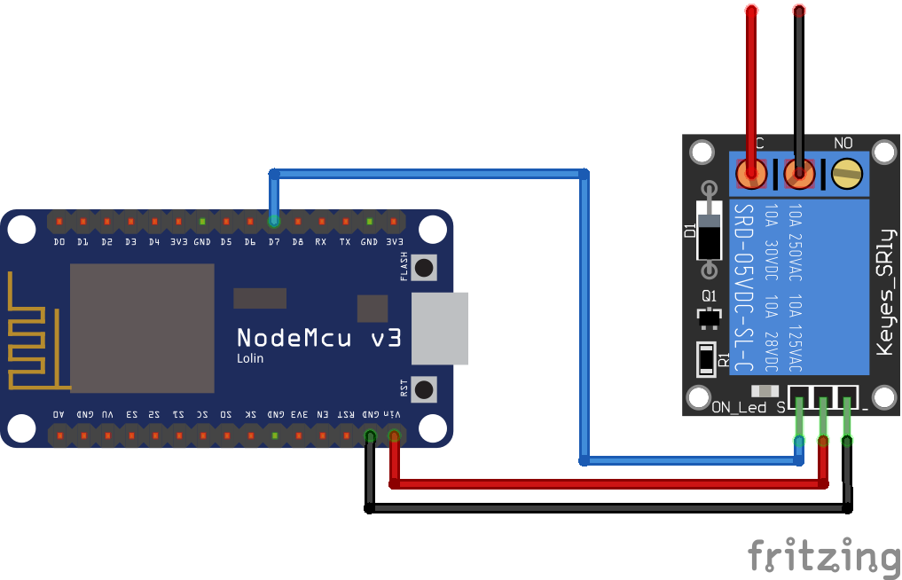
Relais Module NodeMCU
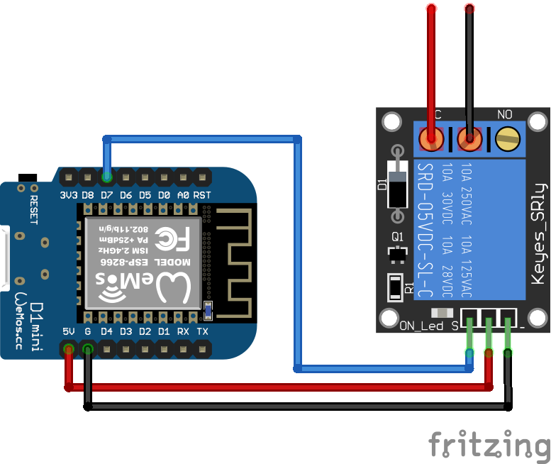
Relais Module ESP8266 WeMos D1 Mini
Relais Module Arduino Nano
Relais Module Arduino Pro Mini
Relais Module Arduino Uno
Relais Module Arduino Mega
Relais Module ESP32 NodeMCU
Relais Module NodeMCU
Relais Module ESP8266 WeMos D1 Mini
Muy bueno el tutorial, te quería preguntar porque me gustaría manejar las luces a través de ok Google a distancia tenés un tutorial para hacerlo. Muchas gracias nicolastortarolo@gmail.com 1168376540
Hola, lamentablemente no tengo un tutorial para el control remoto de luces a través de Google Home
Great content Thanks!
i learned very well about relays
thank you so much