Temperature and Humidity Sensor Tutorial for Arduino, ESP8266 and ESP32
In this tutorial your will learn everything you need to know about the temperature and humidity sensors:
- One Wire Temperature Sensor
- DHT11 Temperature and Humidity Sensor
- DHT22 Temperature and Humidity Sensor
After this tutorial you know the differences between sensor and module.
Moreover you can copy all sketches for your own projects.
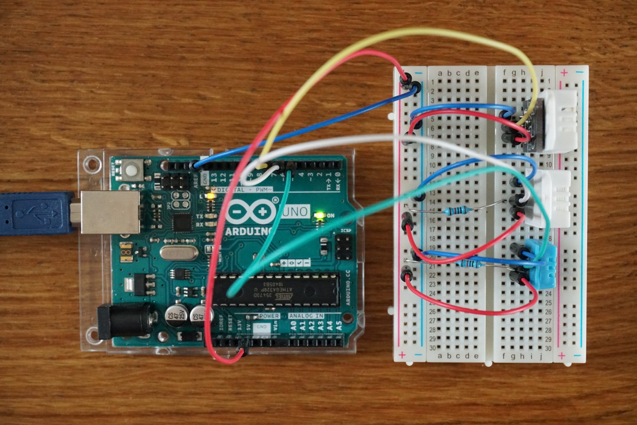
Table of Contents
There a two categories of temperature and / or humidity sensors. The first category are the one wire temperature sensors which provide an analog input as temperature. The second category are the DHT sensors which provide the temperature and humidity via digital input for Arduino, ESP8266 and ESP32 microcontrollers.
The following table gives you an overview of all components and parts that I used for this tutorial. I get commissions for purchases made through links in this table.
| Arduino Uno | Amazon | Banggood | AliExpress | |
| OR | ESP8266 NodeMCU | Amazon | Banggood | AliExpress |
| OR | ESP32 NodeMCU | Amazon | Banggood | AliExpress |
| AND | One Wire Temperature | Amazon | Banggood | AliExpress |
| AND | DHT11 Sensor (blue) | Amazon | Banggood | AliExpress |
| AND | DHT11 Module (blue) | Amazon | Banggood | AliExpress |
| AND | DHT22 Sensor (white) | Amazon | Banggood | AliExpress |
| AND | DHT22 Module (white) | Amazon | Banggood | AliExpress |
One wire temperature sensor
The one wire temperature sensor changes the resistance based on the current temperature. One often used one wire temperature sensor is the LM35 with an operating temperature range of -55°C…150°C. For every degree of temperature change the sensor changes his resistance that the output voltage changes by 10 mV. Therefore the maximum output voltage is (150°C-(-55°C)) * 10 mV/°C = 2.05V.
If you connect the LM35 with an Arduino digital input pin, the internal Arduino analog-to-digital conversation (ADC) converts the analog voltage to a digital value between 0 and 1023.
The default maximum ADC voltage of the Arduino board is 5V and equated to the value of 1023. Based on the maximum ADC voltage the digital input of the LM35 temperature sensor is between 0 and 1023*2.05/5 = 420. This solution will work but you will only use 2.05V/5V = 41% of the digital value range.
That’s why you can set the maximum ADC voltage to other values than 5V. The following table will give you an overview about the possible maximum ADC voltages, how to change the setting in the script and how much of the value range is used.
| Maximum ADC voltage | Function | Percentage of used value range |
| 5V | analogReference(DEFAULT) | 0.41 |
| 3.3V | analogReference(EXTERNAL) | 0.62 |
| 1.1V | analogReference(INTERNAL) | 1.86 |
Can you also use the maximum ADC voltage of 1.1V in this case? The answer is yes, but you will restrict the value range of the temperature sensor. The maximum output voltage changes from 2.05V to 1.1V and we know that the scale factor of the sensor is 10mV/°C. Therefore the maximum temperature with a ADC voltage set to 1.1V is 1.1V/10mV/°C=110°C. The temperature range changes to 0°C…110°C which is for indoor use chases a good and the most precise solution.
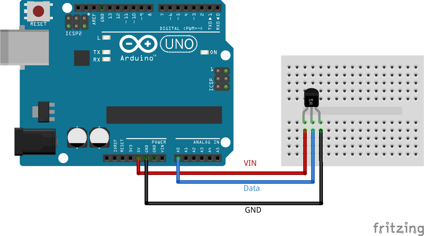
The wiring is pretty easy and straightforward. If the flat side of the LM35 one wire temperature sensor is looking up to you, the left bin is the power pin you connect to the Arduino 5V pin. The right pin is ground, therefore connect the right pin to GND. And the middle pin is the data pin you can connect to every analog input pin. I connected the data pin to A0 on the Arduino Uno
You have to use an analog pin on your microcontroller board to read the analog value of the one wire temperature sensor. If you have an Arduino, you will not have any problem because the Arduino boards have quite some analog input pins. But if you have an ESP8266 microcontroller with only one analog input pin, you may have a problem when this one pin is already in use and you do not want to use an analog multiplexer.
If you want to know how to use an analog multiplexer in combination with your NodeMCU to read multiple analog values, look at this article.
You find the datasheet from the used LM35 temperature sensor from Texas Instruments here.
After wiring the temperature sensor correctly we can use the following sketch to plot the corresponding temperature with the Serial Plotter of the Arduino IDE. We will set the baud rate to 9600. Make sure that the baud rate in the sketch and in your Serial Plotter are the same.
float tempc; //variable temperature (degree Celsius)
float tempf; //variable temperature (Fahreinheit)
float vout; //temporary variable sensor reading

void setup() {
Serial.begin(9600);
}

void loop() {
vout=analogRead(A0); //Reading the value from sensor

//analogReference(DEFAULT);
//// convert analog values between 0 and 1023 with 5000mV ADC
//vout = (vout/1023) * 5000;

analogReference(EXTERNAL);
// convert analog values between 0 and 1023 with 3300mV ADC
vout = (vout/1023) * 3000;

//analogReference(INTERNAL);
//// convert analog values between 0 and 1023 with 1100mV ADC
//vout = (vout/1023) * 1100;

// for every degree the output voltage changes 10 mV
tempc=vout/10;

tempf=(vout*1.8)+32; // Converting to Fahrenheit

Serial.print("in DegreeC=");
Serial.print(" ");
Serial.print(tempc);
Serial.print("\t");
Serial.print("in Fahrenheit=");
Serial.print(" ");
Serial.print(tempf);
Serial.println();
delay(2000);
}
DHT11 and DHT22 Temperature and Humidity Sensor
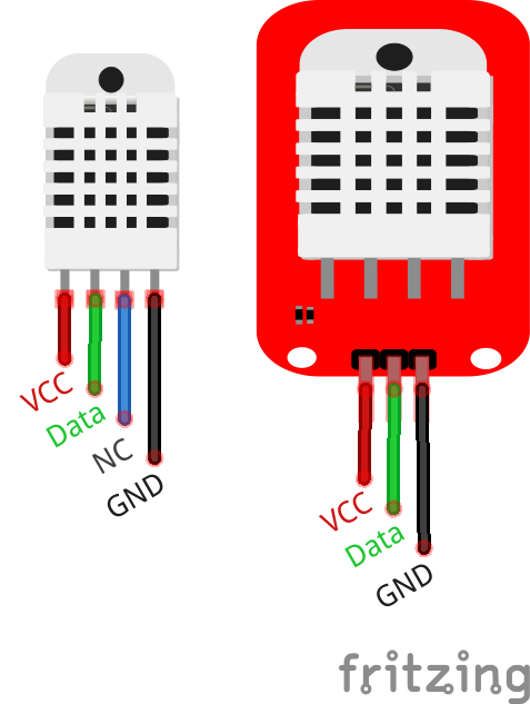
You can buy the DHT11 and DHT22 temperature and humidity as a sensor or as a module. Regarding performance there is no difference if you buy the sensor itself or the module. There are only 2 differences between the sensor or the module. The module is basically the sensor printed onto a circuit board (PCB) in combination of a 10 k Ohm pull-up resistor between the signal and 5V connection. The second difference is that the sensor has a 4-pin package out of which only three pins will be used whereas the module has only the three relevant pins.
If you want to know what the function of a pull-up resistor is, than read this article.
The DHT sensors measure the temperature with a surface mounted NTC temperature sensor (thermistor). If you want to know how a thermistor works, here is an extra article about thermistors. Humidity is measured by the change in resistance between two electrodes and a moisture holding substrate between the two electrodes.
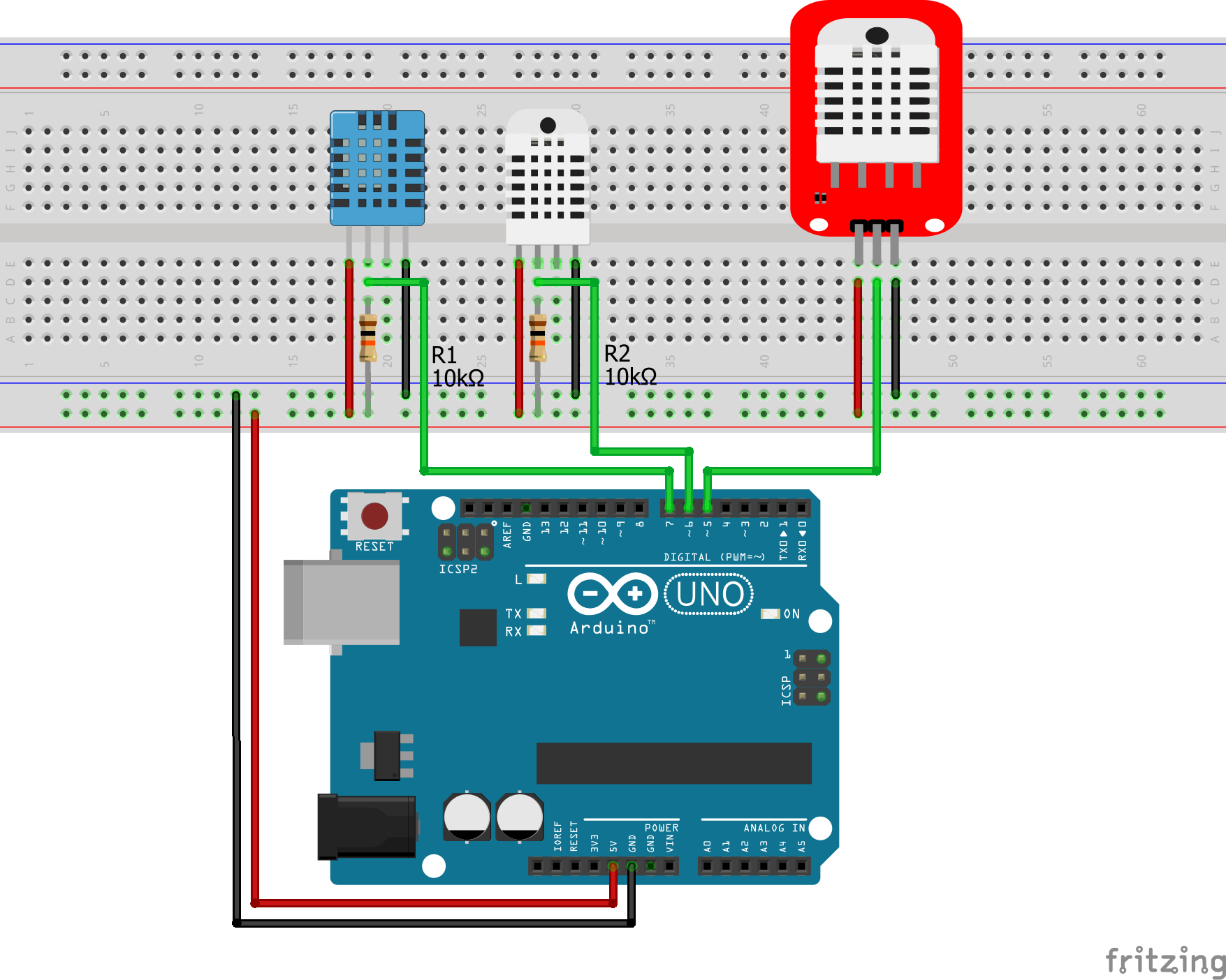
The following picture show how to connect a DHT11 or DHT22 temperature and humidity sensor to your Arduino and NodeMCU. One picture for the version with the up resistor and one version without the pull-up resistor on the PCB, where you have to add the resistor yourself.
| DHT Sensor | DHT Module | Arduino Uno / NodeMCU |
| VCC | VCC | 5V / VIN |
| Data | Data | Digital I/O Pin XXX |
| Nc | – | – |
| GND | GND | GND |
To use the DHT11 or DHT22 sensor in your sketch, you have to download the library of the sensors. The corresponding library is called: “DHT.h”
You find here an article how to install an external library via the Arduino IDE.
After you installed the library successful you can include the library via: #include . This will call the external library and take care of your sketch. The following sketch will read the temperature and humidity of a DHT11 sensor, DHT22 sensor and DHT22 module every 10 second and print the value to the serial output.
#include "DHT.h"

#define DHT11PIN 7        // define the digital I/O pin
#define DHT22PIN 6        // define the digital I/O pin
#define DHT22modulePIN 5  // define the digital I/O pin

#define DHT11TYPE DHT11         // DHT 11
#define DHT22TYPE DHT22         // DHT 22
#define DHT22moduleTYPE DHT22   // DHT 22 module

DHT dht11(DHT11PIN, DHT11TYPE);
DHT dht22(DHT22PIN, DHT22TYPE);
DHT dht22module(DHT22modulePIN, DHT22moduleTYPE);

void setup() {
  Serial.begin(9600);

  dht11.begin();
  dht22.begin();
  dht22module.begin();
}

void loop() {
  // Read all temperature and humidity sensor data
  float h11 = dht11.readHumidity();
  float t11 = dht11.readTemperature();
  float h22 = dht22.readHumidity();
  float t22 = dht22.readTemperature();
  float h22module = dht22module.readHumidity();
  float t22module = dht22module.readTemperature();

  // check if returns are valid and print the sensor data
  if (isnan(t11) || isnan(h11)) {
    Serial.println("Failed to read from DHT #1");
  } else {
    Serial.print("Humidity 11: ");
    Serial.print(h11);
    Serial.print(" %\t");
    Serial.print("Temperature 11: ");
    Serial.print(t11);
    Serial.println(" *C");
  }
  if (isnan(t22) || isnan(h22)) {
    Serial.println("Failed to read from DHT #2");
  } else {
    Serial.print("Humidity 22: ");
    Serial.print(h22);
    Serial.print(" %\t");
    Serial.print("Temperature 22: ");
    Serial.print(t22);
    Serial.println(" *C");
  }
  if (isnan(t22module) || isnan(h22module)) {
    Serial.println("Failed to read from DHT #2");
  } else {
    Serial.print("Humidity 22module: ");
    Serial.print(h22module);
    Serial.print(" %\t");
    Serial.print("Temperature 22module: ");
    Serial.print(t22module);
    Serial.println(" *C");
  }
  Serial.println();   // print a free line to make the output nicer
  delay(10000);       // print new values every 10 seconds
}
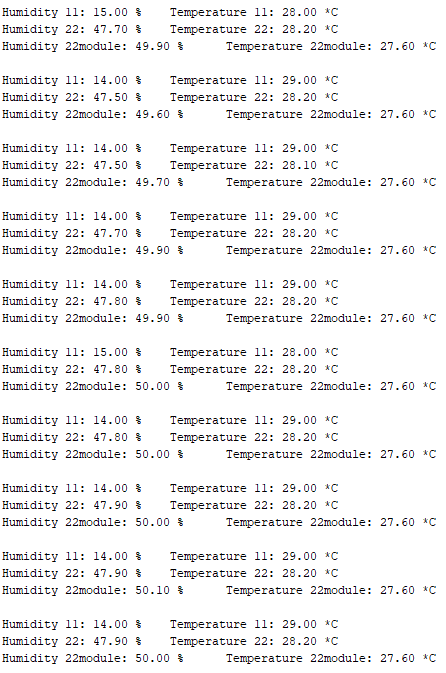
The following picture shows the serial output of the script. You see that the humidity sensor of my DHT11 sensor is broken. The differences in the humidity (~2%) and temperature (~1.5*C) are within the normal range.
How to choose the right temperature and humidity sensor?
The following table give you an overview about the specifications of the temperature and humidity sensors. I would always chose the DHT22 sensor because in every project I want to know the temperature I also want to the humidity. Moreover the temperature range and the accuracy are ways better than the DHT11 sensor.
| DHT11 (blue) | DHT22 (white) | LM35 | |
| Temperature range | 0°C…50°C | -40°C…80°C | -55°C…150°C |
| Temperature accuracy | +- 2°C | +- 0.5°C | +- 0.5°C |
| Humidity range | 20%…90% | 0%…100% | n.a. |
| Humidity accuracy | +- 5% | +- 3% | n.a. |
| Sampling rate | 1Hz (one every 1 second) | 0.5Hz (once every 2 seconds= | |
| Operating voltage | 3V…5V | 3V…5V | 4V…30V |
| Current consumption | 2.5mA | 2.5mA | 60μA |
Conclusion
I hope you enjoyed this article about temperature and humidity sensors. We learned a lot about the two different temperature sensors: one-wire temperature sensor and the temperature sensor with integrated humidity sensor DHT11 and DHT22.
Do you have any further questions about temperature and humidity sensors? Use the comment section below to ask your questions.
Best of the best , Cream of tthe cream
Thank you Ahmad Tolba, big motivation for me to write new article.
hey just wondering why we need to connect the output of the dht modules to 5v through a resistor?
Hey just wondering why we need to connect the output of the DHT modules to the 5v rail through a resistor?
Hi Dean,
the resistor is a pull-up resistor to avoid a shortage.