Headless Thumbnail

Raspberry Pi Headless Setup Tutorial

Raspberry Pi Headless Setup Tutorial

In this tutorial you learn how to do a Raspberry Pi headless setup without a monitor, mouse or keyboard.

In total there are 3 steps we have to make for the Raspberry Pi headless setup.

  1. Download and Install the Raspberry Pi OS (former Raspbian)
  2. Enable SSH and WiFi for Remote Access
  3. Connect to Raspberry Pi via SSH and set static IP configuration.
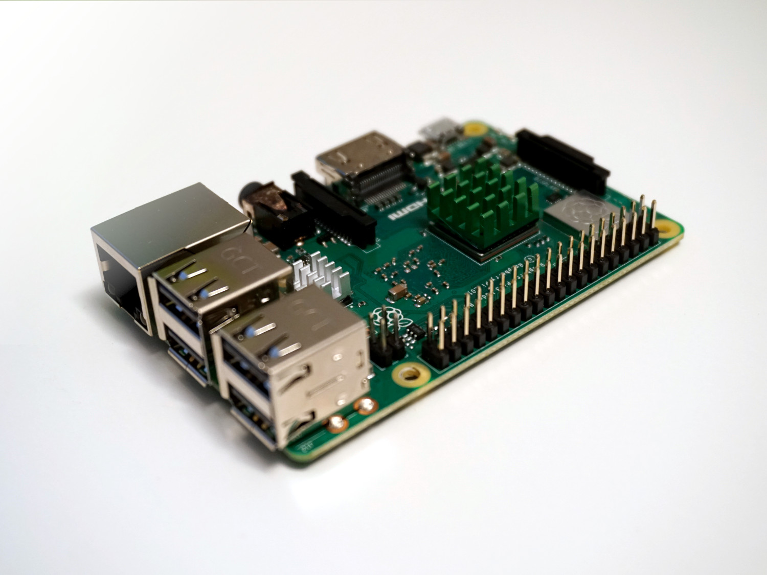
Table of Contents

Because we do not need anything but the Pi itself, it is called a headless setup. This makes the setup really fast and you do not have to switch mouse and keyboard between Raspberry Pi and your PC.

In total it will take around 20 minutes including all downloads and settings.

The following table gives you an overview of all components and parts that I used for this tutorial. I get commissions for purchases made through links in this table.

Raspberry Pi 4 Model B Kit Amazon AliExpress
OR Raspberry Pi 4 Model B Amazon Banggood AliExpress
OR Raspberry Pi 3 B+ Kit Amazon AliExpress
OR Raspberry Pi 3+ Amazon Banggood AliExpress

Download and Install the Raspberry Pi OS

Download 5 minutes, install 5 minutes

The first step is to download the official or recommended operating system for Raspberry Pi, Raspberry Pi OS, former Raspbian Buster. You can download the software was torrent or zip file from the official website.
There are in total 3 different versions of the operating system:

  1. Raspberry Pi OS (32-bit) with desktop and recommended software (~ 2550 MB)
    The additional recommended software is for example LibreOffice, ClawsMail, Minecraft, Scratch, Sonic Pi, RealVNC, and a few other bits and bobs. If you want to use your Pi as a PC with a mouse, keyboard and monitor I would recommend to install this version of the OS.
  2. Raspberry Pi OS (32-bit) with desktop (~ 1150 MB)
    This is in my opinion the default version of the Raspbian OS. We get the desktop, the Chromium web browser, the VLC media player and the Thonny Python IDE, plus a few desktop utilities. Also we can install the software we need after the setup. But I do not like to have plenty of software under the hood that I do not need. Also I need the desktop interface because in my smart home usage I want to display some graphs by connecting the Raspberry Pi to my TV.
  3. Raspberry Pi OS (32-bit) Lite (~ 450 MB)
    The light version of the OS does not come with a desktop graphical interface. In some cases and if you are an advanced user you can use the light version. But keep in mind that you have to use SSH every time.

I would recommend to download
Raspberry Pi OS (32-bit) with desktop. After the download is complete we have to install the operating system on the SD card. There are several software programs to do this task but Etcher is most used. Etcher is a free and open-source software to write images like .iso or .img file to storage media like USB sticks or SD cards. Download Etcher from the official website.

After the installation open Etcher. You should see the following screen.

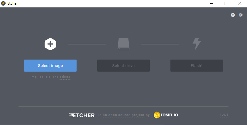
First we have to select the image. We select the Raspbian OS zip file that we downloaded some minutes ago.

Rasbperry Pi OS 202006

The second step is to select the drive we want to install the image. Therefore we choose the SD card as driver.

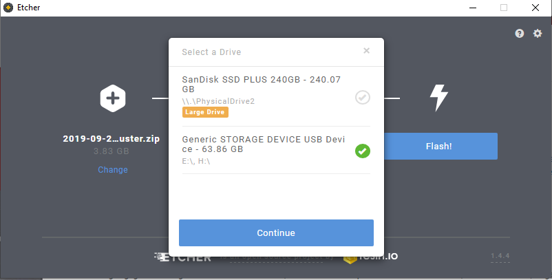
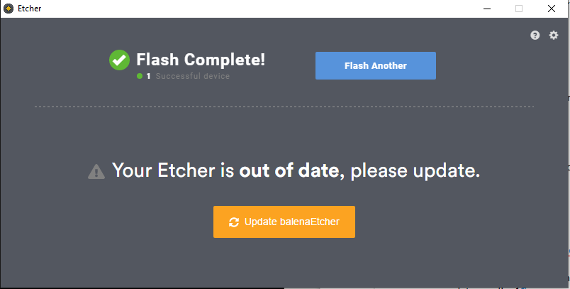
Now we can start the flashing which will take around 5 minutes. After the flashing and validation process is finished the SD card is ejected.

For a non headless setup you would insert the SD card in the Raspberry Pi and you are good to go. But for the headless setup we have to make sure that we can access the Raspberry Pi via the network remotely via SSH before starting the Raspberry Pi. In the next chapter the enabling of SSH is described.

Enable SSH and WiFi for Remote Access

5 Minutes

Because after the flashing the SD card was ejected we have to pull the SD card out and in again. Now start the command prompt. There are multiple ways to do:

  •  Use the search and type “command prompt”
  • Press Windows + R to open the run window and type in “cmd”

Now after we started the command prompt we want to know under which character the SD card is listed to enter this drive. To list all disks we can use the command

wmic logicaldisk list brief

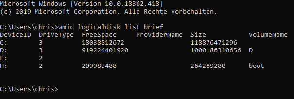
In my case I know that the SD card has the deviceID H.

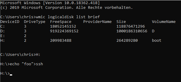
With the command “H:” I am able to access the SD card. Now we have to create a file called ssh. This will show the Raspberry Pi that we want to enable SSH for remote access. To create such a file type in the following command

echo “foo”>ssh

With the command “exit” we leave the command prompt.

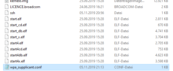
The alternative and faster way is to create the ssh file is to access the SD card with your file explorer and create a text data called “ssh”, but make sure you delete the “.txt”.

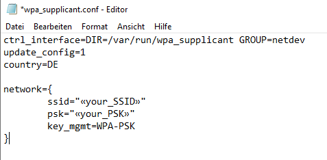
Now we are able to connect the Raspberry Pi via SSH. If you use a local LAN network you are ready to go to the next and final part of this tutorial. If you want to use the Raspberry Pi only with WiFi, we have to make sure that the Pi is able to connect via WiFi. Therefore we create an other file called “wpa_supplicant.conf”. Create a text data from your explorer and delete the “.txt” again. Now open the config file with your Editor and fill the file with the following text:

ctrl_interface=DIR=/var/run/wpa_supplicant GROUP=netdev
update_config=1
country=DE
           
network={
	ssid="«your_SSID»"
	psk="«your_PSK»"
	key_mgmt=WPA-PSK

Because I live in Germany I have to use DE for the country. If you live in the USA you use US. The key is related to the ISO3166-1 Alpha-2 code.

Also you have to add your SSID and password into that file and the WiFi encryption:

  • Wired Equivalent Privacy (WEP)
  • Wi-Fi Protected Access (WPA)
    • WPA-PSK
    • WPA2-PSK
  • Extensible Authentication Protocol (EAP)
    • EAP-PSK.

After the ssh and wpa_supplicant.conf file is created we eject the SD card manually. Now we can insert the SD card in the Raspberry Pi, connect the Pi to the network or use the WiFi connection and power the Raspberry Pi up.

Connect to Raspberry Pi via SSH and set static IP configuration

5 Minutes

To access the Raspberry Pi via SSH we have to know the IP address of the Pi. Therefore we need an IP scanner software. A common used free software which I also use is Advanced IP Scanner which is a free, fast and powerful network scanner with a user-friendly interface. You can download the Advanced IP Scanner from the official website. After installing and starting the software you can scan your local network for active IP addresses.

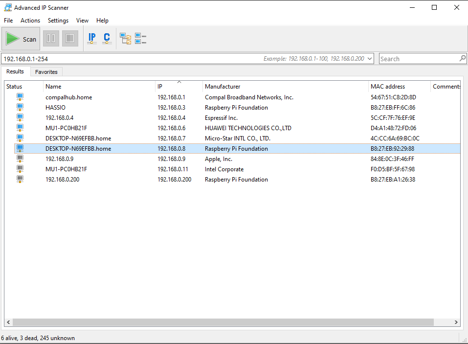
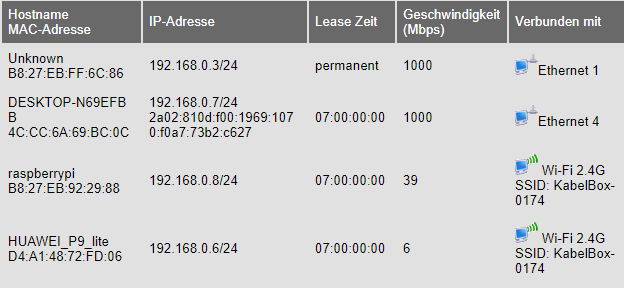
The alternative is to log in to your modem and look for connected devices. In my case the IP address is: 192.168.0.8

To access the Raspberry Pi via SSH we need a terminal emulator which supports the SSH network protocol. The most used program for this is Putty which you can download also from the official website. Putty is also free and open-source. After downloading and installing Putty, open the software. You should see a screen like the following.

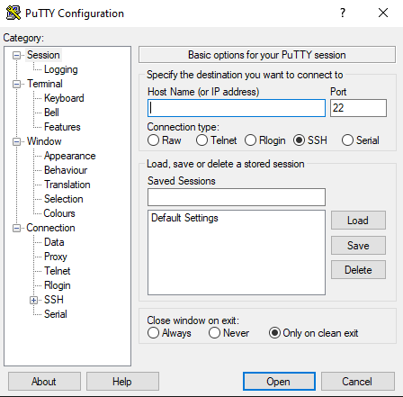
Type in the IP of the Raspberry Pi for the Host Name. The Port for the connection is 22. Select the connection type to SSH and click Open to establish the connection.

At the first connection you will get the following security alert that the servers host key is not cached in the registry.

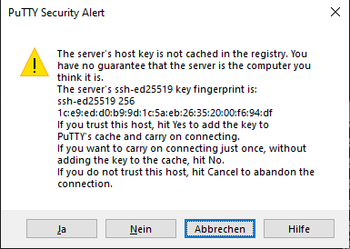
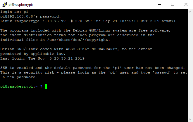
We confirm the connection with Yes. Now we have to provide the username and password. You use the following default settings:

  • Username: pi
  • Password: raspberry

Congratulation you are logged in over WiFi to your Raspberry Pi!

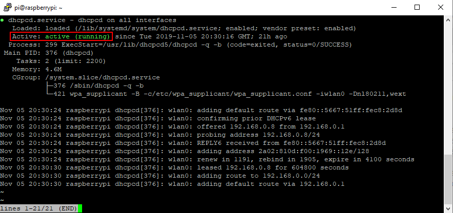
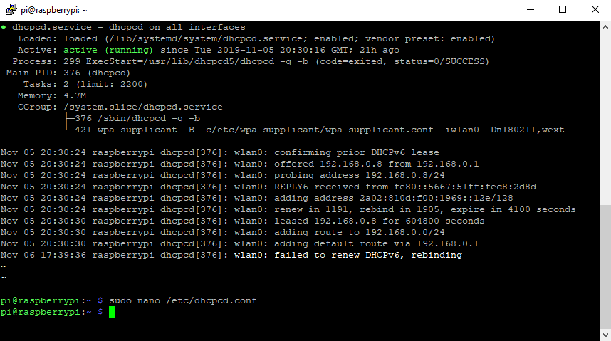
Because every time you restart the Raspberry Pi the modem will give the Pi another IP address, we change the IP address to a static IP. Therefore we need dhcpcd which operates as a daemon on a server to provide Dynamic Host Configuration Protocol service to a network. First we have to check if dhcpcd is active:

sudo service dhcpcd status

With the keyboad combination of Ctrl + C you get back to the main console. If dhcpcd is not active we start the dhcpcd service with the following two commands:

sudo service dhcpcd start
sudo systemctl enable dhcpcd

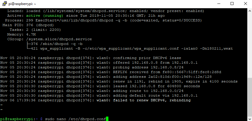
Now we have to provide the configuration for the dhcpcd. Therefore we create a config file with the preinstalled unix text editor nano:

sudo nano /etc/dhcpcd.conf

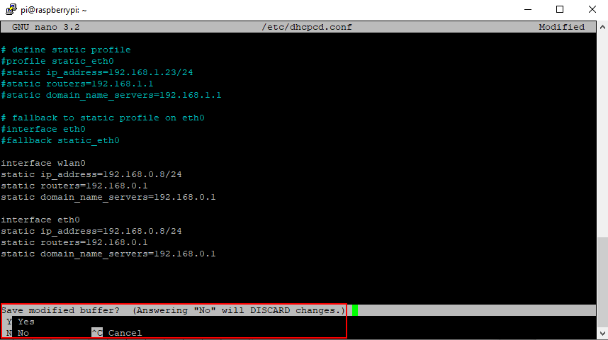
Now you are in the nano text editor. Navigate with the arrow down on you keyboad to the bottom of the text data. Copy the following lines and paste them with a click on your mouse right in your config data.

interface wlan0
static ip_address=192.168.0.8/24
static routers=192.168.0.1
static domain_name_servers=192.168.0.1

interface eth0
static ip_address=192.168.0.8/24
static routers=192.168.0.1
static domain_name_servers=192.168.0.1

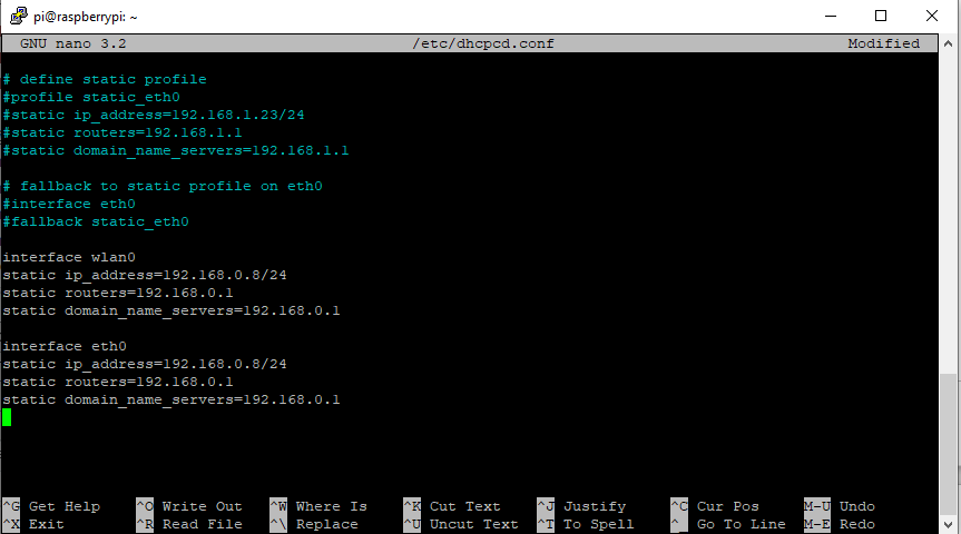
I will use the IP address 8 for the WiFi and Ethernet connection but you can choose a different IP address. Also if you changes the default domain server IP you have to change the IP of the domain server. The /24 after the IP address refers to how many bits are contained in the network.
As all IPv4 networks have 32 bits, and each “section” of the address denoted by the decimal points contains eight bits, “192.0.2.0/24” leaves eight bits to contain host addresses. This is enough space for 256 host addresses. You find more information on this website.

You save the nano text data while exiting the file. Click Ctrl + X, then Y to confirm to save and hit the enter button to save to the existing file. Now you are back to the main console and configured the static IP.

Update Raspberry Pi OS

To make sure that your Raspberry Pi is up to date use now the following two commands to update all packages on your Pi.

sudo apt-get update
sudo apt-get dist-upgrade

Now your Raspberry Pi is ready to go for you projects. If you want to shut down or reboot the Pi use the following commands.

sudo shutdown now
sudo reboot

Do you have any questions regarding the headless setup for the Raspberry Pi? Or do you have general questions about the Pi. Do not hesitate and use the comment section below to ask me your questions.

If you want to start a first project with your Raspberry Pi already setup, I want to recommend you the following two tutorials to build you own DIY smart home indoor weather station:

  1. Microcontroller to Raspberry Pi WiFi MQTT communication
  2. Visualize MQTT Data with InfluxDB and Grafana
PWM thumbnail

PWM Tutorial for Arduino, ESP8266 and ESP32

PWM Tutorial for Arduino, ESP8266 and ESP32

In this tutorial we focus on Pulse Width Modulation (PWM) for the Arduino, ESP8266 and ESP32 microcontroller.

PWM is an important part to control different devices with your microcontroller.

For example you can control the brightness of an LED or the speed of a motor by changing the PWM.

PWM thumbnail

Table of Contents

How does PWM work?

The digital inputs / outputs on your microcontroller have a constant voltage of 3.3V (for ESP8266 and ESP32 boards) or 5V (for Arduino boards). But in some cases you want to control the voltage to a specific value between 0V and the maximum voltage.

In case of PWM, a signal is pulsing between HIGH (3.3V or 5V) and LOW (0V). How often the signal is changing between HIGH and LOW is defined by the PWM frequency. The PWM frequency on Arduino pins are 976 cycles per seconds (Herz), for the ESP8266 up to 1 kHz and for the ESP32 up to 40 MHz.

To generate a PWM signal you use the function analogWrite(pin, value). This function create a square wave PWM signal. You can control the shape of the PWM signal with the duty cycle of (value/255). A 0% to 100% duty cycle corresponds to a value between 0 and 255.

The following table shows broadly the relation between the duty cycle and the average output voltage if the maximum voltage is 5V for Arduino microcontroller and 3.3V for ESP8266 and ESP32 microcontroller.

Duty Cycle Output voltage (Arduino) Output voltage (ESP8266 and ESP32) analogWrite(X)
0% 0V 0V 0 = 0%*255
0.25% 1.25V 0.825V 63.75 = 25%*191.25
0.5% 2.5V 1.65V 127.5 = 50%*255
0.75% 3.75V 2.475V 191.25 = 75%*255
100% 5V 3.3V 255 = 100%*255

I used my oscilloscope to measure the duty cycles of the table above for the Arduino output voltage. Therefore I connected digital pin 11 of the Arduino Uno to my PicoScope and set up a measurement for the duty cycle. You can do the exactly same measurement for the ESP8266 or the ESP32

The code for the quick measurement is the following. For each measurement I changed the value for the analogWrite function.

Duty Cycle 0%
Note that the 0% duty cycle is measured as 100% because there is no square wave at 0% and also at 100%. Therefor be careful how the duty cycle is measured. In my case I have to see if the voltage is 0 at 100% duty cycle.

Duty Cycle 25%

Duty Cycle 50%

Duty Cycle 75%

Duty Cycle 100%

Create PWM Examples

The following table gives you an overview of all components and parts that I used for this tutorial. I get commissions for purchases made through links in this table.

Arduino Uno Amazon Banggood AliExpress
OR ESP8266 NodeMCU Amazon Banggood AliExpress
OR ESP32 NodeMCU Amazon Banggood AliExpress
AND Resistor and LED in Package Amazon Banggood AliExpress
AND DC Motor Amazon Banggood AliExpress
AND L298N Motor Driver Module Amazon Banggood AliExpress

Change the brightness of an LED by PWM

In the following example we want to change the brightness of an LED by changing the duty cycle of the regarding PWM signal.

The following fritzing sketches show the circuit done with different Arduino, ESP8266 and ESP32 microcontroller boards. We have to make sure that the LED is connected to a microcontroller pin that is PWM able.

I recommend to get the Microcontroller Datasheet eBook where you can find the pinouts of the different microcontroller boards, that include the information which pins are able to use PWM. You get the eBook for free if you join the DIYI0T newsletter.

PWM LED Arduino Nano

PWM LED Arduino Nano

PWM LED Arduino Pro Mini

PWM LED Arduino Pro Mini

PWM LED Arduino Uno

PWM LED Arduino Uno

PWM LED Arduino Mega

PWM LED Arduino Mega

PWM LED ESP32 NodeMCU

PWM LED ESP32 NodeMCU

PWM LED ESP8266 NodeMCU

PWM LED ESP8266 NodeMCU

PWM LED ESP8266 WeMos D1 Mini

PWM LED ESP8266 WeMos D1 Mini

The program code is pretty straight forward. We have to define the pins and some variables for the time and the height to increment the brightness of the LED. If you want to know how to change the color for multicolor LEDs, using different PWM signals, you find this in my LED tutorial.

int LEDpin = 11;   // for Arduino microcontroller
//int LEDpin = D4;   // for ESP8266 microcontroller
//int LEDpin = 4;   // for ESP32 microcontroller

int bright = 0;    // initial value of LED brightness
int incremt = 5;   // incremental change in PWM frequency
int time = 100;    // time period the PWM frequency is changing

void setup()
  {
    pinMode(LEDpin, OUTPUT);  // define the LEDpin as output pin
  }

void loop()
  {
    analogWrite(LEDpin, bright);  // set LED brightness as PWM signal
    delay(time);                  // wait for a time period
    bright = bright + incremt;    // increment LED brightness
    // if the brightness is out of range, reduce brightness
    if (bright <=0 || bright >=255) incremt = - incremt;
  }

In the first part of the Arduino code, we define the pin that connects the LED to the microcontroller. Because this script is for Arduino, ESP32 and ESP8266 microcontrollers, you have to comment out two of the first three lines that defines the pin.

Also we have to define three additional variables:

  • bright: initial value of the LED brightness and therefore 0 to shut down the LED.
  • increment: the incremental change in the PWM frequency. Each increment the LED increases and decreases the brightness.
  • time: the time period in milliseconds for each PWM cycle.

In the setup function, we fine the pin, that we defines as LED pin at the beginning of the script, as output pin to use the pin with PWM.

We start the loop function, with the analogWrite(pin, value) function we set the analog value (PWM wave) for the brightness to the LED pin. After the delay of 0.1 seconds, the brightness in incremented. If the brightness reaches the minimum (0) or maximum (255) value, the increment is changed from a positive value to a negative value.

The following video shows the change of the brightness of the LED due to the PWM function.

Control the speed of an DC motor by PWM

The second example shows how we can change the speed of an DC motor with the help of a PWM signal. We use the L298N motor driver module to connect the Arduino, ESP8266 or ESP32 to the DC motor. Also it is recommend to power the DC motor with an external power supply. Therefore I use 4 AA batteries, each with 1.5V so in total 6V.
I want to focus on the PWM signal in this example. Therefor I do not further describe the DC motor example. But if you are interested in DC motors, I will write an extra article about DC motors, that explains everything in detail.

DC Motor L298N Arduino Nano

DC Motor L298N Arduino Nano

DC Motor L298N Arduino Pro Mini

DC Motor L298N Arduino Pro Mini

DC Motor L298N Arduino Uno

DC Motor L298N Arduino Uno

DC Motor L298N Arduino Mega

DC Motor L298N Arduino Mega

DC Motor L298N ESP32 NodeMCU

DC Motor L298N ESP32 NodeMCU

DC Motor L298N ESP8266 NodeMCU

DC Motor L298N ESP8266 NodeMCU

DC Motor L298N ESP8266 WeMos D1 Mini

DC Motor L298N ESP8266 WeMos D1 Mini

For the program code we want to increase the motor speed each second. At the start, the voltage provided through the PWM signal is to low to start the motor. This is why it takes some intervals in the for loop until the motor is turning.

// Arduino connection to L298N
int enA = 10; // PWM for Motor A
int in1 = 9;  // Control Rotation of Motor A
int in2 = 8;  // Control Rotation of Motor A

// ESP8266 connection to L298N
//int enA = D4; // PWM for Motor A
//int in1 = D5;  // Control Rotation of Motor A
//int in2 = D6;  // Control Rotation of Motor A

// ESP32 connection to L298N
//int enA = 4; // PWM for Motor A
//int in1 = 0;  // Control Rotation of Motor A
//int in2 = 2;  // Control Rotation of Motor A

int motor_speed = 0; 

void setup()
{
  // set all the motor control pins to outputs
  pinMode(enA, OUTPUT);
  pinMode(in1, OUTPUT);
  pinMode(in2, OUTPUT);
}

void loop()
{
  // run the motor between 0 and 250 in increments of 10
  digitalWrite(in1, LOW); // Input1 LOW = move forward
  digitalWrite(in2, HIGH);  // Input2 HIGH = move forward
  for(motor_speed = 0; motor_speed < 250; motor_speed += 10)
  {
    analogWrite(enA, motor_speed); // PWM output
    delay(1000);
  }
}

In the first part of the script we define the pins that connect the microcontroller to the L298N module, that is connected to the DC motor. In total we have to define 3 pins:

  • enA: transfers the PWM signal to the L298N module and must be a pin that is able to produce a PWM signal.
  • int1 and int2: control the rotation direction of the motor. The following table shows how to control int1 and int2 to stop the motor, move forward and move backwards.
int1
LOW HIGH
int2 LOW Motor stops Motor moves backwards
HIGH Motor moves forward Motor stops

Because this script is for Arduino, EPS8266 and ESP32 microcontroller boards, you have to select only the lines for your microcontrolle and comment the other lines. The current script is commented in a way, that is for Arduino boards.

To increase the motor speed, the speed has to be saved to a variable that we call motor_speed and has an initial value of 0.

In the setup function we define all digital pins, that connects the board to the L298N as outputs.

We start the loop function by setting int1 LOW and int2 HIGH. Therefore the DC motor rotates in the forward direction. In the for loop we increase the motor speed each second by 10 between 0 and 250. The motor speed in written as analog output (PWM signal) to the enA connection.

The following video shows the Arduino script in action for the Arduino Uno as example.

Conclusion

I hope you enjoined this article about the PWM signal. The PWM signal is a very handy tool which is used a lot in practical examples. It is recommended to know how PWM is working. Therefore if you have any further questions, use the comment section below to ask.

Raspberry Pi vs Arduino

Raspberry Pi vs Arduino Comparison

Raspberry Pi vs Arduino Comparison

In this article you learn the differences between the Raspberry Pi and the Arduino and why I use both of them in my projects.

The Raspberry Pi vs Arduino comparison is done in different categories:

  • System and Operating System
  • Connections and GPIOs
  • Data Transfer
  • Operating Power and Power Consumption
  • Advantages and Disadvantages
  • Area of Applications
Raspberry Pi vs Arduino

Table of Contents

The objective of this article is not to find out what hardware is better because we will see that they really not compare in the same segment. Moreover the Raspberry Pi and the Arduino supplement each other very well.

The following table shows the summary of this entire article. But I recommend to read the whole article to really understand the differences. Also I link to other articles on my blog if you want to get more detailed information about a specific topic.

Important: The following table compare the Raspberry Pi 3 Model B+ and the Arduino Uno R3. Because there are different models of each on the market, the exact comparison will differ, but the trend remain the same.
If you are interested in the comparison of the different Raspberry Pi models, you find the comparison on Wikipedia and for the different micro-controller you find the comparison in this article.

Raspberry Pi 3 Model B+ Arduino Uno R3
System Single Board Computer (SBC) Micro-Controller
Operating System Run on an operating system No operating system
Connections PC based connections like HDMI, USB, … and GPIOs Hardware oriented connections like GPIOs, power jack, USB plug
Data Transfer Files can be transferred any time via FTP, USB or the SD card Data can only be transferred via the flash of the microcontroller
Program Execution Multiple programs can run at the same time Only one program can run at once
Processor Broadcom BCM2837B0 AVR ATmega328p
Clock Speed 1.4GHz 16MHz
Register Width 64-bit 8-bit
RAM 1 GB 2 kB
GPIO Ports 5V, 3.3V and Ground Digital I/O pins but no analog pin 5V, 3.3V and Ground Digital I/O pins along with analog pins
# GPIO 40 20
I/O Maximal Current 50 mA 50 mA
Power consumption 700 mW 175 mW
Advantages Highly flexible with different operating systems and able to run multiple applications at the same time. Perfect to read sensor values and control actors like motors. Easy to program with a lot of tutorials.
Disadvantages More expensive and can not read analog sensor values Usage is limited due to lack of computation power and no operating system
Area of Application Connection of multiple devices and run multiple applications at the same time Connection of sensors and actors to the internet and enable IoT applications
Price $35 to $52 $12 to $18

The following table gives you an overview of all components and parts that I used for this tutorial. I get commissions for purchases made through links in this table.

Arduino Nano Amazon Banggood AliExpress
Arduino Uno Amazon Banggood AliExpress
Arduino Mega R3 Amazon Banggood AliExpress
Raspberry Pi 4 Model B Kit Amazon AliExpress
Raspberry Pi 4 Model B Amazon Banggood AliExpress
Raspberry Pi 3 B+ Kit Amazon AliExpress
Raspberry Pi 3+ Amazon Banggood AliExpress

System

The comparison of a Raspberry Pi and the Arduino is difficult because the system differs. The Raspberry Pi is a single board computer (SBC) and is therefore a real PC or laptop like the one you have only on a single board. On the other side the Arduino is a micro-controller. So what is the exact difference?

The Raspberry Pi has a microprocessor which is a single CPU consisting of only registers for analog data storage, an analog arithmetic unit (ALU) and a control unit (CU). The RAM and secondary storage are external and not part of the CPU.

The micro-controller of the Arduino on the other hand has a build in chip which consists of RAM, ROM, I/O, timers and CPU inside the chip. Therefore there are no external parts needed along with the chip to be fully usable.

AVR 7810 Architecture

Because there is no measurement if a micro-controller or a micro-processor is better both parties get 0 points.

0

Raspberry Pi vs Arduino

0

Operating System

The most used and from the Raspberry Pi Foundation official supported operating system for the Raspberry Pi is Raspbian. If you want to know to to install Raspbian I wrote a step by step tutorial in this article. There are a lot of other operating systems which focuses on different use cases. For IoT projects there is Windows 10 IoT or Hass.io. Also you can install Ubuntu on your Raspberry Pi.

Because the Arduino is a micro-controller and no micro-processor, the Arduino has no operating system. The program you create is directly compiled into machine language during the flash process and then executed. This is the reason that you can not change the program during the run-time. If you make a change on your program you have to re-flash the micro-controller.

Because for the Raspberry Pi is the opportunity to install an operating system, the Pi get one point.

1

Raspberry Pi vs Arduino

0

Connections

The connections of the Raspberry Pi are nearly the same as your PC or laptop. It has several USB ports and an HDMI output as well as an Ethernet port. To connect a camera the Pi has a CSI camera connector and to connect other sensors, there are in total 40 GPIOs. But there is no analog pin because the Raspberry Pi does not have an analog to digital converter.

The connections of the Arduino are designed to connect different sensors. Therefore there are 20 GPIOs. Because the Arduino has a build in analog to digital converter, there are several analog pins. The Arduino have a power jack and USB plug for power supply.

Because the Raspberry Pi has more connections the Raspberry Pi get this point again.

2

Raspberry Pi vs Arduino

0

Data Transfer

For the Raspberry Pi data is stored on a SD card. Therefore there are several possibilities to transfer data from you local PC or laptop to the SD card.

  • The easiest option is to plug the SD card directly in your PC or laptop and copy data or files on the SD card. After the data is copied you plug the SD card into the Pi and the Pi can access the data.
  • Because the Raspberry Pi can read data from USB, you can also plug in an USB stick or external hard drive via USB with the data.
  • The most convenient option is to send the data via FTP and the local network. You can use an FTP program like FileZilla

Because the Arduino is only able to use machine language, there is no possibility to store data onto the micro-controller. Files in form of variables have to be flashed via the Arduino IDE. If you are new to the Arduino IDE, here is a tutorial how to use the Arduino IDE.

The Raspberry Pi has the ability to transfer files easy over the network. This point goes to the Pi.

3

Raspberry Pi vs Arduino

0

Operating Power

Because the Raspberry Pi is more or less a full PC, the operating power is enormous compared to the Arduino. The clock speed is nearly 90 times and the RAM 500,000 higher. Moreover the Arduino runs only on 8-bit compared to the 64-bit of the Raspberry Pi.

With the beefy power of the Pi this point has to go to the Raspberry Pi.

4

Raspberry Pi vs Arduino

0

GPIOs

Over the last version of the Raspberry Pi the number of usable GPIOs has increased. Therefore the Raspberry Pi has 40 pins available, but no analog pin. In my opinion the 20 GPIOs from the Arduino are no downside because until now I did not have a projects where I needed all pins. In case there is a project where I would need more pins there are 2 options:

  1. Use and Arduino Mega with 54 digital pins
  2. Use a multiplexer
    1. 16-Channel Analog Multiplexer/Demultiplexer: CD74HC4067
    2. 8-Bit Shift Registers for more digital I/O: 74HC595

The maximal current per pin is with 50 mA the same for the Arduino and Raspberry Pi.

Because the Arduino can read analog sensor values this point goes straight to the Arduino.

4

Raspberry Pi vs Arduino

1

Power Consumption

The Raspberry Pi has a much higher power consumption compared to the Arduino. Also there are several possibilities to reduce the power consumption for micro-controller. The most known example is the NodeMCU. The NodeMCU is also a micro-controller and can be used for an Arduino. With the deep sleep mode activated the power consumption reduces to 50 μA which is very handy for battery powered projects. On the other hand to Raspberry Pi is not able to run on a non stationary project.

The power consumption of the Arduino is very low and therefore suitable to run on battery. This point is for the Arduino.

4

Raspberry Pi vs Arduino

2

Advantages

The main advantage in my opinion of the Raspberry Pi is the operating system. There are a lot of pre-configured software which let you directly start your project. For example if you want to build a security camera you can download the motionEyeOS operating system and finish the project in record time.
Also you can run multiple applications at the same time. For example surf with the web browser through the internet while in the background sensor values are stored in a SQL database and a backup is done.

The Arduino as a micro-controller is more hardware oriented compared to the Raspberry Pi and therefore perfect to read sensor values or to control a motor. For a beginner I would suggest to start with an Arduino because there are a lot of tutorials and you can start directly after you downloaded the Arduino IDE.

Disadvantages

The main disadvantage of the Raspberry Pi is the price because a good micro-controller starts with $5 to get your first IoT projects running. Compared to the Arduino or ESP based micro-controllers the Raspberry Pi is up to 10 times more expensive. Also if you want for example build a smart indoor weather station

  • the Raspberry Pi is too large,
  • you do not need all the computation power,
  • have to think about the heating and
  • the project would be too expensive.

Also the Pi is not able to read analog sensor values.

For heavy computation tasks, the Arduino does not have the computation power and not the designed operating system. Therefore a lot of task can not be done because programs from the Linux or an other distribution cannot be installed.

Area of Applications

In my projects there is always an Arduino or NodeMCU involved inline with a Raspberry Pi. I use the micro-controller to read sensor values or to control an actor like a motor. The Arduino or NodeMCU is for me the gateway to the local network. Sensor data are send via MQTT from the micro-controller to the Raspberry Pi, stored in a database and visualized or further processed. This is why I do not compare the Arduino and the Pi. For me both are the perfect solution to different problems.

If you have any questions about the Raspberry Pi, the Arduino or other micro-controllers, please use the comment section below to ask questions. I will answer them as soon as possible.

Servo Motors Thumbnail

Servo Motor Tutorial for Arduino, ESP8266 and ESP32

Servo Motor Tutorial for Arduino, ESP8266 and ESP32

In this tutorial you learn everything you need to know about the functionalities of a servomotor.

First we learn the theoretical foundations how a servomotor works.

In multiple example you learn how to control one or multiple servo with your Arduino, ESP8266 or ESP32 microcontroller.

Servo Motors Thumbnail

Table of Contents

A servomotor is an electric motor which can precisely control the angle position, velocity and acceleration. Therefor the motor is using a closed-loop feedback mechanism. A Servo consists of the following parts:

  • An electric motor (DC motor, asynchronous motor or synchronous motor)
  • A sensor for position feedback
  • A controller to regulate the movement of the motor according to one or more adjustable setpoints, such as the desired angular position of the shaft or setpoint speed, in a control loop.

Servos are used in applications like robotics, CNC machines and different fields of automation technology.

Closed-loop Servomechanism

As mentioned at the beginning of this tutorial the servomotor uses a closed-loop feedback system to control the angle position, velocity and acceleration. The following picture shows the closed-loop.

servo motor position control diagram

Forward path:
The input for the driver is a pulse signal, which will be provided by our microcontroller in the following examples of this tutorial. The pulse signal define the position adjustment for the servo which results in a speed command and final in a current command which is the input for the inverter to turn the motor in the preferred direction.
There are different types of motors that can be used for a servo because the servomotor is not depended on the motor but on the functionality with the closed feedback loop. The most used motors are from brushed permanent magnet DC motors which are simple and cheap to AC induction motors for industrial use.

Backwards path:
The motor is paired with an encoder to provide speed and position feedback. The current feedback is provided directly by the inverter.
In out example we use a cheap servo motor which only uses the position feedback via a potentiometer. Therefore the motor always rotates at full speed. For industrial uses servomotors have a speed feedback loop as well through an optical rotary encoder. These types of servo are able to control the speed and therefore reach the desired position faster and precisely with less overshotting.
The position feedback to control the motion and the final position is compared to input signal. If there is a difference, an error signal is generated. The error signal causes the servo to rotate in the preferred direction until the error signal is zero. If the error signal is zero, the final position is reached and the motor stops rotating.

Input Pulse Signal

Now we want to control the servomotor with our Arduino, ESP8266 or ESP32 microcontroller. Therefore the pulse signal as input has to be created from the microcontroller as a square wave similar to a PWM signal.

Because we do not create a PWM signal, the digital pin for the motor does not have to be a PWM pin on your board. Every digital pin will work.

Most servo motors especially the cheaper ones which I use are not able to turn full 360 degrees but rather are able to turn between 0 and 180 degrees. With the PWM signal, the control is

  • 0 degrees for a pulse width of 1 ms,
  • 90 degrees with a pulse width of 1.5 ms and
  • 180 degrees with a 2 ms pulse width.

The total cycle time is 20 ms where the PWM is repeated. The following picture shows the three different positions with their pulse with.

Longruner SG90 Micro Servo Motor 9G RC (KY66-5)

The servo I use is the Longruner SG90 Micro Servo Motor 9G RC (KY66-5). The following table shows the data sheet for the motor.

Operating speed 0.12second/ 60degree ( 4.8V no load)
Stall Torque (4.8V) 17.5oz /in (1kg/cm)
Operating voltage 3.0V~7.2V
Temperature range -30 to +60 degree Celsius
Dead band width 7µs
Working Frequency 50Hz
Motor Type Brushed DC Motor
Gear Type Plastic Gears
Dimensions 23 x 11.5 x 24mm
Weight 9 grams

The stall torque is the torque the motor is pushing against a difference to the current position if you want to spin the motor with your hand. With a wide range of operating voltage the servo is able to work with Arduino boards (5V supply voltage) and EPS8266 boards (3.3V supply voltage).

The following table gives you an overview of all components and parts that I used for this tutorial. I get commissions for purchases made through links in this table.

Arduino Uno Amazon Banggood AliExpress
OR ESP8266 NodeMCU Amazon Banggood AliExpress
OR ESP32 NodeMCU Amazon Banggood AliExpress
AND Servo Motors Amazon Banggood AliExpress
AND Potentiometer Amazon Banggood AliExpress
AND PCA9685 16-Channel Servo Driver Amazon Banggood AliExpress

We will use the Servo library in the following examples. If you do not know how to install a library in the Arduino IDE, here is a tutorial.

If we use the Servo library the PWM functionality on pin 9 and pin 10 of the Arduino boards are automatically disabled.

Turn the Servo to 180 degrees

The first example is the easiest one you can image. We want to turn the motor from 0 to 180 degrees in a step size of 1 and after pausing at 180 degrees for one second we want to turn the motor backwards to 0 degree but with a faster step size of 5.

The following pictures how the wiring between the Arduino, ESP8266 or ESP32 microcontroller and the servo motor.

Servo Arduino Nano

Servo Arduino Nano

Servo Arduino Pro Mini

Servo Arduino Pro Mini

Servo Arduino Uno

Servo Arduino Uno

Servo Arduino Mega

Servo Arduino Mega

Servo ESP32 NodeMCU

Servo ESP32 NodeMCU

Servo ESP8266 NodeMCU

Servo ESP8266 NodeMCU

Servo ESP8266 WeMos D1 Mini

Servo ESP8266 WeMos D1 Mini

After the wiring between the microcontroller and the servo motor, we create the Arduino script that moves the servo motor forward to a degree of 180 and back to 0 degree. I describe the script that is written for Arduino, ESP8266 and ESP32 microcontroller boards in detail.

#include "Servo.h"

int servo_pin = 9;  // for Arduino microcontroller
//int servo_pin = D7;  // for ESP8266 microcontroller
//int servo_pin = 4;  // for ESP32 microcontroller

Servo myservo;
int angle = 0;  
 
void setup() 
{ 
  myservo.attach(servo_pin);
} 
  
void loop() 
{ // move from 0 to 180 degrees with a positive angle of 1
  for(angle = 0; angle < 180; angle += 1)
  {                          
    myservo.write(angle);
    delay(15);                       
  } 

  delay(1000);
  
  // move from 180 to 0 degrees with a negative angle of 5
  for(angle = 180; angle>=1; angle-=5)
  {                                
    myservo.write(angle);
    delay(5);                       
  } 

    delay(1000);
}

At the beginning of the script we include the Servo library that makes the operation of the servo motor a lot easier.

Then we have to define the digital I/O pin that connects the microcontroller to the servo motor. Because the used pin depends on the microcontroller, I created in total 3 lines of code that matches the wiring pictures before. Dependent on your microcontroller you have to comment 2 lines and uncomment the line of code that matches your microcontroller.

Now we can initialize a servo object from the previous included servo library.

Out objective is to rotate the servo to a certain degree in each loop of the program code. Therefore we need a variable to store the current angle of the motor. The initial value of the angle is 0.

In the setup function we use the attach function of the servo object to tell the object, that the servo motor is connected to the servo pin.

In the loop function we need two for loops to turn the motor from 0 degree to 180 degrees and a second function that moves the motor back to 0 degree but with another speed.

Therefore in each for loop we use the write function of the myservo object to define the absolute angle that the servo should turn. This angle can be positive and also negative.

In the first for loop we increase the angle each loop by +1 and use a delay of 15 milliseconds. Therefore the motor turns relative slow.

In the second loop function, where we want to move the servo back to 0 degree, we decrease the angle every loop by 5 and use a delay of 5 milliseconds. The motor turns faster from 180 degrees to 0 degree.

At the end of the script we wait for 1 second and start the loop function all over again.

The following video, shows the Arduino script in action with an Arduino Uno as example.

Define the Angle of the Servo Motor with a Potentiometer

In the second example we want to use a potentiometer to set the angle of the servo motor. Therefor we read the value of the potentiometer which is between 0 and 1023, re-scale the value between 0 and 180 to move the motor between 0 and 180 degrees.

The following picture show the wiring between the Arduino, EPS8266 or ESP32 microcontroller board, the servo motor and the potentiometer.

Servo Potentiometer Arduino Nano

Servo Potentiometer Arduino Nano

Servo Potentiometer Arduino Pro Mini

Servo Potentiometer Arduino Pro Mini

Servo Potentiometer Arduino Uno

Servo Potentiometer Arduino Uno

Servo Potentiometer Arduino Mega

Servo Potentiometer Arduino Mega

Servo Potentiometer ESP32 NodeMCU

Servo Potentiometer ESP32 NodeMCU

Servo Potentiometer ESP8266 NodeMCU

Servo Potentiometer ESP8266 NodeMCU

Servo Potentiometer ESP8266 WeMos D1 Mini

Servo Potentiometer ESP8266 WeMos D1 Mini

#include "Servo.h"

// for Arduino microcontroller
int servo_pin = 9;  
int potpin = 0;

// for ESP8266 microcontroller
//int servo_pin = D7;
//int potpin = A0;

// for ESP32 microcontroller
//int servo_pin = 4;
//int potpin = 0;
 
Servo myservo;
int val;
 
void setup() {
  myservo.attach(servo_pin);
}
 
void loop() {
  val = analogRead(potpin);
  val = map(val, 0, 1023, 0, 180);
  myservo.write(val);
  delay(15);
}

The first part of the Arduino script is very similar to the previous one. At the start we have to include the servo library and define the pins that connect the microcontroller board with the servo. Because we have another connected component in this example, we also have to define the analog pin that connects the potentiometer and the Arduino, ESP8266 or ESP32 board.

If you are not sure which pins of the Arduino, ESP8266 or ESP32 microcontroller board can be used to connect different electrical components, I can recommend the Microcontroller Datasheet eBook.

After we initialize a servo object, we create an variabel to store the value of the potentiometer that is between 0 and 1023.

The setup function stays the same, we only have to tell the servo object at which pin the motor is connected.

In the loop function, we read the analog value of the potentiometer and map the value range of the potentiometer (0…1023) to the value range of the servo (0…180). After the mapping of the values, we set the angle of the servo to the mapped value of the potentiometer with the write function and include a short delay of 15 milliseconds to make sure that the servo is able to rotate in the desired position.

The following video shows how the servo is rotating, controlled by the potentiometer.

Connect Multiple Servo Motors

Of cause it is possible to connect multiple servos to your microcontroller and the Arduino Mega has a lot of pins. But there is a smarter way to connect multiple servos to your Arduino or NodeMCU using the I2C connection. If you want to know more about the I2C connection, you find a complete guide in this article.

PCA9685 16-Channel Servo Driver

To connect multiple servo motors over I2C we use the PCA9685 16-Channel Servo Driver which uses an on-board PWM controller to drive all 16 channels at the same time. Additionally you are able to connect multiple PCA9685 16-Channel Servo Drivers in a chain up to 62 drivers. Therefore we are able to control up to 992 servos with the 2 I2C pins.

PCA9685

The connection between the PCA9685 and the microcontroller is easy and shown in the following table as well as in the fritzing sketch.

PCA9685 Description Arduino ESP32 ESP8266
GND Ground GND GND GND
VCC Logic power pin which should be between 3V and 5V 5V 3.3V 3.3V
V+ Optional power pin to supply the servo motors. Either connect V+ to VIN or use the 2-pin terminal block at the top of the PCA9685 board. Provide 5V DC to 12V DC. Note: Do not connect V+ and the 2-pin terminal at the same time. VIN VIN
SCL I2C clock pin SCL pin (19) SCL pin (22) SCL pin (D1)
SDA I2C data pin SDA pin (18) SDA pin (21) SDA pin (D2)
OE Can be used to quickly disable all output when pulled HIGH. We do not use the functionality

If you do not know the SCL and SDA pins for your microcontroller, you find the pinouts for each board in the following articles: Arduino Nano, Arduino Uno, Arduino Mega, ESP8266, ESP32 or better in the Microcontroller Datasheet Playbook.

The 16 output ports (V+, GND and PWM) can be used to connect servos or LEDs. All outputs use the same PWM frequency which can be 1 kHz for LEDs and 60 Hz for servos. The maximum current per pin is 25mA. If you only use some servos like up to five you can power them from your microcontroller. But if you want to use more motors, I would recommend to power the servos with the 2-pin terminal and an external power supply. In the list of the parts you find some good choices for an external power supply.

Wiring between the PCA9685 and the Microcontroller

The following pictures shows the wiring when we do not use an external power source for the PCA9685 board.

Servo PCA9685 Arduino Nano

Servo PCA9685 Arduino Nano

Servo PCA9685 Arduino Pro Mini

Servo PCA9685 Arduino Pro Mini

Servo PCA9685 Arduino Uno

Servo PCA9685 Arduino Uno

Servo PCA9685 Arduino Mega

Servo PCA9685 Arduino Mega

Servo PCA9685 ESP32 NodeMCU

Servo PCA9685 ESP32 NodeMCU

Servo PCA9685 ESP8266 NodeMCU

Servo PCA9685 ESP8266 NodeMCU

Servo PCA9685 ESP8266 WeMos D1 Mini

Servo PCA9685 ESP8266 WeMos D1 Mini

And if we want to use a lot of servo motors and and therefore need an external power supply, we have to disconnect the connection between V+ and the microcontroller and therefore connect the PCA9685 to an external power supply between 5V and 12V.

Servo PCA9685 External Power Supply Arduino Nano

Servo PCA9685 External Power Supply Arduino Nano

Servo PCA9685 External Power Supply Arduino Pro Mini

Servo PCA9685 External Power Supply Arduino Pro Mini

Servo PCA9685 External Power Supply Arduino Uno

Servo PCA9685 External Power Supply Arduino Uno

Servo PCA9685 External Power Supply Arduino Mega

Servo PCA9685 External Power Supply Arduino Mega

Servo PCA9685 External Power Supply ESP32 NodeMCU

Servo PCA9685 External Power Supply ESP32 NodeMCU

Servo PCA9685 External Power Supply ESP8266 NodeMCU

Servo PCA9685 External Power Supply ESP8266 NodeMCU

Servo PCA9685 External Power Supply ESP8266 WeMos D1 Mini

Servo PCA9685 External Power Supply ESP8266 WeMos D1 Mini

Parameterize your Servo Motor

Before we can start with the example itself, we have to parameterize our servo motors to find the exact 0 degree and 180 degree position, when the motor is controlled by the PCA9685. Therefore we use the sketch from the first example and have to remember the exact position of the plastic attachment on the motor.

Now we have to find the optimal values for two parameters: MIN_PULSE_WIDTH and MAX_PULSE_WIDTH to define the position of the servo at 0 degree and 180 degrees. The following picture shows the desired result. I found that for the Longruner SG90 Micro Servo Motor 9G RC (KY66-5) the parameters are the following:

  • MIN_PULSE_WIDTH = 600
  • MAX_PULSE_WIDTH =2600
Find the Min and Max Pulse Width

Because these values are depending on you individual servos, we now have to find the optimal values for your servo motors.

Find value of MIN_PULSE_WIDTH

We use a part of the future full sketch to let the motor settle at 0 degree. Use the following sketch and change the values for MIN_PULSE_WIDTH until the desired position is achieved. Maybe you will overshoot the position, then you have to tweak the parameter again.

The Arduino script might look a little complicated but I explain everything in detail. Also most of the following script is reusable for us for the actual example.

#include "Wire.h"
#include "Adafruit_PWMServoDriver.h"
Adafruit_PWMServoDriver pwm = Adafruit_PWMServoDriver(0x40);

#define MIN_PULSE_WIDTH 600
#define MAX_PULSE_WIDTH 2600
#define FREQUENCY 50

void setup() {
  pwm.begin();
  pwm.setPWMFreq(FREQUENCY);
  // find MIN_PULSE_WIDTH: set angle to 0
  // find MAX_PULSE_WIDTH: set angle to 180
  pwm.setPWM(0,0,pulseWidth(0)); // 0 or 180
}

int pulseWidth(int angle) {
  int pulse_wide, analog_value;
  pulse_wide = map(angle, 0, 180, MIN_PULSE_WIDTH, MAX_PULSE_WIDTH);
  analog_value = int(float(pulse_wide) / 1000000 * FREQUENCY * 4096);
  return analog_value;
}

void loop() {
}

To control the PCA9685 we use the Adafruit_PWMServoDriver library. If you do not know how to install a library you find here a tutorial.

First we include the libraries Wire.h to use the I2C communication and the Adafruit_PWMServoDriver to manage the CA9685 16-Channel Servo Driver board. Then we create an ServoDriver object called pwm with the corresponding I2C HEX address, that is in my case 0x40. To find the right I2C HEX address you can use the I2C HEX code scanner in this article.

Next we define our variables. In this step you need to tweak the parameters MIN_PULSE_WIDTH and set the parameter MAX_PULSE_WIDTH to a fixed value. Nearly all servos use a frequency of 50Hz. You find this information on the data sheet of your motor.

In the setup function the PWM object that we created previously is activated with the frequency of 50Hz. Also we control the servo motor with the setPWM function of the pwm object. The function contains 3 arguments:

  1. On which position of the PCA9685 is the servo connected. The numbers are printed on the board starting with 0 up to 15.
  2. Constant 0
  3. Function to specify the angle: pulseWidth(angle) where angle can be between 0 and 180.
    1. To find the optimal value for MIN_PULSE_WIDTH, set the angle to 0
    2. To find the optimal value for MAX_PULSE_WIDTH, set the angle to 180

Because we only want to parameterize the servo motor, we need this one iteration from the setup function and have to change the value of MIN_PULSE_WIDTH to get the 0 degree position. Therefore we do not need a loop function.

Now we create the function pulseWidth to calculate the analog value for the motor depending on the desired angle. First the pulse with is calculated between 0 degree and 180 degrees depending on the minimum and maximum pulse width with the map function. Then the analog value for the servo is calculated by dividing the pulse wide by 1,000,000 to convert the value to us per second and multiplied with the frequency and 4096 for a 12 bit resolution. At the end of this function, this analog value is returned.

Find value of MAX_PULSE_WIDTH

 If you found the right value for MIN_PULSE_WIDTH we do the same with MAX_PULSE_WIDTH  to find the motor position for 180 degrees. We use the same program code and change the value for MAX_PULSE_WIDTH until the 180 degrees position is found. Also you have to change the value for angle in the setPWM function to 180. The value of MIN_PULSE_WIDTH  has to be fixed.

Control Multiple Servo Motors with the PCA9685

In this example we want to use 3 servo motors at the same time. The script has no direct practical use but shows how to control multiple servos in one script over the I2C connection.

#include "Wire.h"
#include "Adafruit_PWMServoDriver.h"
Adafruit_PWMServoDriver pwm = Adafruit_PWMServoDriver(0x40);

#define MIN_PULSE_WIDTH 600
#define MAX_PULSE_WIDTH 2600
#define FREQUENCY 50

void setup() {
  pwm.begin();
  pwm.setPWMFreq(FREQUENCY);
}

int pulseWidth(int angle) {
  int pulse_wide, analog_value;
  pulse_wide = map(angle, 0, 180, MIN_PULSE_WIDTH, MAX_PULSE_WIDTH);
  analog_value = int(float(pulse_wide) / 1000000 * FREQUENCY * 4096);
  return analog_value;
}

void loop() {
  pwm.setPWM(0, 0, pulseWidth(0));
  pwm.setPWM(1, 0, pulseWidth(180));
  delay(1000);
  pwm.setPWM(4, 0, pulseWidth(0));
  delay(1000);
  pwm.setPWM(0, 0, pulseWidth(180));
  pwm.setPWM(1, 0, pulseWidth(90));
  delay(500);
  pwm.setPWM(4, 0, pulseWidth(180));
  delay(1000);
  pwm.setPWM(0, 0, pulseWidth(90));
  pwm.setPWM(1, 0, pulseWidth(0));
  delay(1000);
}

Because we know most of the script already from the parametrization, I will concentrate on the changes that we made for this example.

The first part of the script where we include the libraries, create the pwm object and define the variables are the same. The MIN_PULSE_WIDTH and MAX_PULSE_WIDTH are the values from the parametrization.

In the setup function we do not use the setPWM function to turn the motor. This in done in the loop function, where we turn the servo motors in different angles with the argument of the pulseWidth function.

To differentiale the servos, we change the first argument of the setPWM function to the connection pin on the PCA9685 board. In my case, I have a servo connected to pin 0, 1 and 4.

The pulseWidth function is the same compared to the parametrization.

The following video shows the example in action for the Arduino Uno and ESP8266 NodeMCU.

Using multiple PCA9685 in a chain

As said before, it is possible to connect multiple PCA9685 in a chain to connect up to 992 servos with the 2 I2C pins on your microcontroller.
The following fritzing sketch shows you how to connect multiple PCA9685 boards.

Servo Arduino multiple PCA9685

You can use the sketch of the previous example and you only have to change the Hex address and create as many ServoDriver objects as you connect PCA9685 boards. The objects could be called pwm1, pwm2, etc. with the individual I2C HEX address. As mentioned before you can use the I2C HEX code scanner from this article to find the right addresses.

Conclusion

In this tutorial we learned a lot about servo motors. First we studied to theory about servos and the functionality. In the second part of the tutorial we got to the practical examples and started with basics examples to turn to motor up to 180 degrees and return to 0 degree. Also we succeeded to turn the servo depending on the position of a potentiometer. After the simple example we learned how to control multiple servos with the PCA9685 and how to connect multiple PCA9685 boards.
If you have any question about the functionality of the servo motor or to any example in this tutorial, please use the comment section below to ask you questions so that I can answer them directly.

_DSC1783

Arduino Interrupts and Timed Events

Arduino Interrupts and Timed Events

In this tutorial you learn the functionality of Arduino interrupts and how to time events with this function.

The advantage of timed events is to perform a specific task when an event occurs, Independence of the current task that the microcontroller is performing, like sending important sensor data, even if the Arduino is stuck in a delay function.


Table of Contents

The objective for Arduino interrupts is to perform a specific task independent of other performed tasks or programs which take place in the setup or loop function. Common examples are:

  • Measuring an incoming signal at equally spaced intervals (constant sampling frequency)
  • Calculating the time between two events
  • Sending out a signal of a specific frequency
  • Periodically checking for incoming serial data

There are many task like a for loop or the execution of Arduino libraries which are made up of many commands, where it is not possible to predict the computation time of a single task. Therefore we need a different approach to interrupt the loop function, run a specific task and than continue to execute the loop function.

Depending on your microcontroller, your have multiple timer available to work with. Every timer has a counter which increments the timer on each tick of the timers clock. The ATmega328 which is build on the Arduino Uno has in total 3 timers available. If you do not know what microcontroller is build on your board, you find an overview in this article of the most used boards.

After we know our microcontroller, the following table shows how many timers are available and their size and pin for the connection. Also you find the clock frequency for the chip, which is the fastest speed the timer can increment the counter.

ATmega168, ATmega328 ATmega1280, ATmega2560
Timer 0 8-bit, PWM Max value of 255. 8-bit, PWM Max value of 255.
Timer 1 16-bit, PWM Max value of 65535. 16-bit, PWM Max value of 65535.
Timer 2 8-bit, PWM Max value of 255. 8-bit, PWM Max value of 255.
Timer 3 16-bit, PWM Max value of 65535. 16-bit, PWM Max value of 65535.
Timer 4 16-bit, PWM Max value of 65535. 16-bit, PWM Max value of 65535.
Timer 5 16-bit, PWM Max value of 65535. 16-bit, PWM Max value of 65535.
Clock frequency 16 MHz 16 MHz

Arduino Interrupts

The often in Arduino boards used ATmega328 chip has in total 3 counters. One of the timer is 16 bit and both others are 8 bit in size. The clock frequency of the chip is 16MHz which means that one tick needs around 63ns.

If you think that this is fast than you are right. Honestly you are more than right because these clock frequency is too fast for interrupts and timed events. The 8 bit timer would be reach the maximum entry in 256/16,000,000s = 16μs and the 16 bit timers in 256/16,000,000s = 4ms.
If we want to interrupt the loop function every second than are these timers not very useful.

But there is a solution called prescaler for this problem. The prescaler is a constant from the values 8, 64, 245, 1024 which reduces the clock speed as a factor:
Speed of timer (Hz) = Clock speed (16MHz) / prescaler

Clear Timer on Compare or CTC Mode

CTC timer interrupts are events which are triggered when the timer reaches a predefined value. This value is stored in the compare match register. At the same time the timer is cleared and set to zero and restarts the counting.

The most used timer registers are the following:

  • TCNTx – Timer/Counter Register. The actual timer value is stored here.
  • OCRx – Output Compare Register
  • ICRx – Input Capture Register (only for 16bit timer)
  • TIMSKx – Timer/Counter Interrupt Mask Register. To enable/disable timer interrupts.
  • TIFRx – Timer/Counter Interrupt Flag Register. Indicates a pending timer interrupt.

If we want to interrupt every second, the value in the match register is = (clock speed / prescaler * interrupt frequency) -1. We have to subtract 1 because the match register is zero indexed (depends on the microcontroller).
For the ATmega328 with greatest prescaler of 1024, the value of the register would be: (16MHz / 1024 * 1Hz) -1 = 15624. Now we have to choose the timer of that 1Hz second interruption. Timer 0 and Timer 2 can not perform that task because their maximum value to store is 255 with 8bit. Therefor only Timer 1 is able to perform the task 15624<65535.

How to setup the prescalers

The prescalers are setup with different clock select bits. You find the description in the Atmega datasheet. The following tables show the selected bits for the Atmel-7810 as example.

Timer 0

CS02 CS01 CS00 Description
0 0 0 No clock source (Timer/Counter stopped)
0 0 1 clkI/O/(no prescaling)
0 1 0 clkI/O/8 (from prescaler)
0 1 1 clkI/O/64 (from prescaler)
1 0 0 clkI/O/256 (from prescaler)
1 0 1 clkI/O/1024 (from prescaler)
1 1 0 External clock source on T0 pin. Clock on falling edge
1 1 1 External clock source on T0 pin. Clock on rising edge.

Timer 1

CS12 CS11 CS10 Description
0 0 0 No clock source (Timer/Counter stopped)
0 0 1 clkI/O/(no prescaling)
0 1 0 clkI/O/8 (from prescaler)
0 1 1 clkI/O/64 (from prescaler)
1 0 0 clkI/O/256 (from prescaler)
1 0 1 clkI/O/1024 (from prescaler)
1 1 0 External clock source on T1 pin. Clock on falling edge
1 1 1 External clock source on T1 pin. Clock on rising edge.

Timer 2

CS22 CS21 CS20 Description
0 0 0 No clock source (Timer/Counter stopped)
0 0 1 clkT2S/(no prescaling)
0 1 0 clkT2S/8 (from prescaler)
0 1 1 clkT2S/32 (from prescaler)
1 0 0 clkT2S/64 (from prescaler)
1 0 1 clkT2S/128 (from prescaler)
1 1 0 clkT2S/256 (from prescaler)
1 1 1 clkT2S/1024 (from prescaler)

Arduino Interrupt Example

In the following example we want to create a sketch with three different interrupts based on the CTC mode:

  1. The first timeout at 2kHz toggles Arduino Uno pin 8
  2. The second timeout at 1Hz toggles Arduino Uno pin 13
  3. The third timeout at 8kHz toggles Arduino Uno pin 9

The script has the following structure

  1. Define variables for the toggling
  2. In the setup function we create the CTC interrupts
    1. Set the 2 registers TCCRxA and TCCRxB to zero
    2. Initialize the counter value TCNTx to 0
    3. Set the value to which the counter value should be compared OCRxA to the following equation: (16*10^6) / (frequency[Hz]*64) – 1
    4. Turn on the CTC mode
    5. Setup the prescalers
    6. Compare the timer for the interrupt
  3. With the function call sei(); we allow interrupts during the run-time of the microcontroller.
  4. Define the functions ISR(TIMERx_COMPA_vect) to define what the Arduino should do when the interrupt has taken place. In this example we set the pin HIGH if there is no interrupt and LOW if there is an interrupt. Therefore we are able to verify the behavior of the interrupt with the oscilloscope.

Basically the structure is for all three interrupts the same. Only the frequency when to interrupt has to be adjusted as well as the registers based on their maximal values.

The following script shows the Arduino code, that we discuss step by step.

//storage variables
boolean toggle0 = 0;
boolean toggle1 = 0;
boolean toggle2 = 0;

void setup(){
  
  //set pins as outputs
  pinMode(8, OUTPUT);
  pinMode(9, OUTPUT);
  pinMode(13, OUTPUT);

cli();//stop interrupts

//set timer0 interrupt at 2kHz
  TCCR0A = 0;// set entire TCCR2A register to 0
  TCCR0B = 0;// same for TCCR2B
  TCNT0  = 0;//initialize counter value to 0
  // set compare match register for 2khz increments
  OCR0A = 124;// = (16*10^6) / (2000*64) - 1 (must be <256)
  // turn on CTC mode
  TCCR0A |= (1 << WGM01);
  // Set CS01 and CS00 bits for 64 prescaler
  TCCR0B |= (1 << CS01) | (1 << CS00);   
  // enable timer compare interrupt
  TIMSK0 |= (1 << OCIE0A);

//set timer1 interrupt at 1Hz
  TCCR1A = 0;// set entire TCCR1A register to 0
  TCCR1B = 0;// same for TCCR1B
  TCNT1  = 0;//initialize counter value to 0
  // set compare match register for 1hz increments
  OCR1A = 15624;// = (16*10^6) / (1*1024) - 1 (must be <65536)
  // turn on CTC mode
  TCCR1B |= (1 << WGM12);
  // Set CS12 and CS10 bits for 1024 prescaler
  TCCR1B |= (1 << CS12) | (1 << CS10);  
  // enable timer compare interrupt
  TIMSK1 |= (1 << OCIE1A);

//set timer2 interrupt at 8kHz
  TCCR2A = 0;// set entire TCCR2A register to 0
  TCCR2B = 0;// same for TCCR2B
  TCNT2  = 0;//initialize counter value to 0
  // set compare match register for 8khz increments
  OCR2A = 249;// = (16*10^6) / (8000*8) - 1 (must be <256)
  // turn on CTC mode
  TCCR2A |= (1 << WGM21);
  // Set CS21 bit for 8 prescaler
  TCCR2B |= (1 << CS21);   
  // enable timer compare interrupt
  TIMSK2 |= (1 << OCIE2A);


sei();//allow interrupts

}//end setup

ISR(TIMER0_COMPA_vect){//timer0 interrupt 2kHz toggles pin 8
//generates pulse wave of frequency 2kHz/2 = 1kHz (takes two cycles for full wave- toggle high then toggle low)
  if (toggle0){
    digitalWrite(8,HIGH);
    toggle0 = 0;
  }
  else{
    digitalWrite(8,LOW);
    toggle0 = 1;
  }
}

ISR(TIMER1_COMPA_vect){//timer1 interrupt 1Hz toggles pin 13
//generates pulse wave of frequency 1Hz/2 = 0.5kHz (takes two cycles for full wave- toggle high then toggle low)
  if (toggle1){
    digitalWrite(13,HIGH);
    toggle1 = 0;
  }
  else{
    digitalWrite(13,LOW);
    toggle1 = 1;
  }
}
  
ISR(TIMER2_COMPA_vect){//timer1 interrupt 8kHz toggles pin 9
//generates pulse wave of frequency 8kHz/2 = 4kHz (takes two cycles for full wave- toggle high then toggle low)
  if (toggle2){
    digitalWrite(9,HIGH);
    toggle2 = 0;
  }
  else{
    digitalWrite(9,LOW);
    toggle2 = 1;
  }
}

void loop(){
}

The following three pictures are screenshots from the oscilloscope, where we can check the frequency of the interrupt. I measured the voltage directly at the output pin of the Arduino Uno. At the bottom of each picture you see that I measured the average of the high pulse width in seconds. If we invert the high pulse width we get the frequency of the interrupt.

Timer0 interrupt at 2kHz

The average high pulse width is 501.9μs with is a frequency of 1.99kHz

Timer1 interrupt at 1Hz

The average high pulse width is 1.002s with is a frequency of 1Hz

Timer2 interrupt at 8kHz

The average high pulse width is 126.1μs with is a frequency of 7.93kHz

Conclusion

In this tutorial we learned a lot about the interrupts and timed events of the Arduino, better said the different ATmega microcontroller. In the example we used only the digital HIGH and LOW function if a timed event takes place. In a real world example we would change the function to something more productive like calculating the time between two events. If you have any questions about this tutorial please use the comment section below.

Reed Switch Thumbnail

Reed Switch Tutorial for Arduino, ESP8266 and ESP32

Reed Switch Tutorial for Arduino, ESP8266 and ESP32

In this tutorial we learn how to build our own security system for doors or windows with a reed switch.

Reed switches are magnetically-actuated electrical switches which switch based on a magnetic field. If magnetic field through a magnet or a strong electrical current is present to the reed switch, the connection inside the switch closes and the circuit is closed so that a current flow is present.

Otherwise if there is no magnetic field, the switch remains open. 

KY-021

Table of Contents

Reed Switch vs Magnetic Hall Sensor

The reed switch is not the only electrical device with can be used as a magnetic switch. There is also the magnetic hall sensor. For some use cases there is no difference if you use a reed switch or a magnetic hall sensor. But a big difference is how the direction of the magnetic field has to be in order to use the magnetic switch. In the following table you find the comparison between the two magnetic switches with the advantages and disadvantage and also how the magnet – sensor orientation has to be.

Magnetic Hall Sensor (KY-003)

Reed Switch (KY-025, KY-021)

Switch Function

Transducer that varies the output voltage depending on the presents of a magnetic field.

Pair of ferrous metal contacts. If contracts are open, there is no electrical contact. The contacts are closed by a magnet near the switch and opened by removing the magnet.

Magnet – Sensor Orientation

Magnet has to be perpendicular to magnetic hall sensor

Magnet has to be parallel to reed switch

Advantages

No moving parts involved

No debouncing effect

Cheaper than magnetic hall sensor

Disadvantages

More expensive than reed switch

Has moving parts that wear

Moving parts are not able over frequencies greater 10 kHz

Switch has debouncing effect like all switches

If you are interested in the (magnetic) hall sensors, I wrote a complete tutorial for this as well.

Use of the Reed Switch

A very common application of reed switches is to detect if a door or window is open or closed. Therefore you have one side of the sensor with the reed switch and an other side with the magnet like you can see in right picture.

Because the magnetic field is directed and therefore has a direction, the position and angle between the reed switch and the external magnet is important. There are two opposite scenarios which are also seen the in two following pictures. On the left side the magnet is parallel to the reed switch and in the right picture, the magnet is perpendicular to the magnetic switch.

Magnet is parallel to reed switch

This is the perfect setup that you also find in the door or window detection use case because the build up magnetic field is parabolic.

Magnet is perpendicular to reed switch

In this setup the magnetic field has a dead zone in the middle of the reed switch. Therefor do not use the magnet and reed switch in a perpendicular setup.

There are two reed switch modules on the market. The KY-025 and the KY-021. The following table compares the technical data sheet between these two reed modules.

KY-025 KY-021
Operating voltage 3.3V...5.5V 3.3V...5.0V
Board dimensions 1.5 cm x 3.6 cm 0.6 in x 1.4 in 1.5 cm x 1.9 cm 0.6 in x 0.75 in
Outputs Analog + Digital Digital
Build in resistor 100kΩ potentiometer 10kΩ

In the following sections, we want to measure the magnetic field with both, the KY-025 and the KY-021. Therefore we take a look in the wiring between the reed switch and the microcontroller. After the wiring is done we create a sketch to measure the magnetic field. Because the KY-021 has only a digital output, we can not measure how strong the magnetic field is, only if a predefined threshold through the 10kΩ resistor is exceeded.

With the KY-025 we gain much better flexibility, because we are able to measure the strength of the magnetic field with the analog output and are able to define the threshold with the potentiometer for our self.

The following table gives you an overview of all components and parts that I used for this tutorial. I get commissions for purchases made through links in this table.

Arduino Uno Amazon Banggood AliExpress
OR ESP8266 NodeMCU Amazon Banggood AliExpress
OR ESP32 NodeMCU Amazon Banggood AliExpress
AND Reed Switch KY-025 and KY-021 in Sensor Pack Amazon Banggood AliExpress

KY-025 Read Analog and Digital Values

In the following example we want to read the analog and digital value of the KY-025 reed switch.

With the analog connection we are able to get the status of the magnetic switch but can not measure exactly how strong the magnetic field is because the switch is very fast. We want to display the switch cycles to the serial output of the Arduino IDE to see that the analog values do not have any information of the strength of the magnetic field and therefore provide not more information than the digital value.

The KY-025 has a build in potentiometer to set the threshold for the digital value to change between 0 and 1 based on the analog value. The digital value is

  • 0 for the threshold is not exceeded (build in LED is off), because the reed switch is open
  • 1 for the threshold is exceeded (build in LED is turned on), because the reed switch is closed

The setup of the threshold is very hard because the sampling rate of the serial communication is not very high. Therefore we can use an oscilloscope with a high sampling rate connected to the analog pin to see the current voltage of the analog pin that is changing when the potentiometer is changed.

To stimulate the reed switch I use a magnet with 2 sides (north and south).

The following pictures show the wiring between the KY-025 and the Arduino, ESP8266 or ESP32 microcontroller. 

KY-025 Arduino Nano

KY-025 Arduino Nano

KY-025 Arduino Pro Mini

KY-025 Arduino Pro Mini

KY-025 Arduino Uno

KY-025 Arduino Uno

KY-025 Arduino Mega

KY-025 Arduino Mega

KY-025 ESP32 NodeMCU

KY-025 ESP32 NodeMCU

KY-025 ESP8266 NodeMCU

KY-025 ESP8266 NodeMCU

KY-025 ESP8266 WeMos D1 Mini

KY-025 ESP8266 WeMos D1 Mini

After we wire the KY-025 and the microcontroller, we can create the Arduino script that displays the analog and digital value of the reed switch. We go step by step over the program code and I explain what we are doing.

// for Arduino microcontroller
int analogPin = A0; 
int digitalPin = 8;

// for ESP8266 microcontroller
//int analogPin = A0; 
//int digitalPin = D8;

// for ESP32 microcontroller
//int analogPin = 4; 
//int digitalPin = 2;

void setup() {
  pinMode(analogPin, INPUT); 
  pinMode(digitalPin, INPUT); 
  Serial.begin(9600);
}

void loop() {
  int analogVal = analogRead(analogPin);
  int digitalVal = digitalRead(digitalPin);
  
  Serial.print(analogVal);
  Serial.print(" - ");
  Serial.println(digitalVal);
  
  delay(100);
}

At the beginning of the script we have to define the pins that connect the microcontroller with the KY-025 module. Because this script can be used for Arduino, ESP8266 and ESP32 microcontroller, if defined all connections but commented the lines for the ESP8266 and ESP32. Therefore if you want to use the script for an ESP microcontroller board, you have to comment the Arduino lines and uncomment the desired ESP lines.

In the setup function, we define the pin mode of the two connection pins as inputs, because we want to read the sensor data of the reed switch. Also we set the baud rate of the serial connection to the PC to 9600 to view the sensor values in the Arduino IDE. The baud rate must match the baud rate of the serial monitor in the Arduino IDE.

In the loop function we read the analog value from the previous defined analog pin and save the analog sensor value as integer variable. We do the same for the digital value but read of cause the digital value from the digital pin.

Now we print both value to the serial monitor and include a short delay of 0.1 seconds before we read the next sensor values in the next iteration of the loop function.

The following videos and pictures show the results of this example:

  • KY-025 Analog Measurement in the Serial Plotter of the Arduino IDE
  • KY-025 Digital Measurement in the Serial Monitor of the Arduino IDE
  • KY-025 Visualize the influence of the potentiometer on the analog sensor value, measured with an oscilloscope

KY-025 Analog Measurement

KY-025 Digital Measurement

KY-025 Digital Arduino

KY-025 Visualize the influence of the potentiometer on the analog sensor value

KY-021 Digital Connection

After the KY-025 we also want to test the KY-021 reed switch that has only a digital output and no build in LED. Therefor I use an external LED with a resistor of 220 ohm in series to visualize that the threshold is exceeded. The LED is connected to a digital pin and ground. Therefore we can use this digital pin to turn the LED on and off.

The following pictures show the wiring between the KY-021 and the Arduino, ESP8266 or ESP32 microcontroller boards.

KY-021 Arduino Nano

KY-021 Arduino Nano

KY-021 Arduino Pro Mini

KY-021 Arduino Pro Mini

KY-021 Arduino Uno

KY-021 Arduino Uno

KY-021 Arduino Mega

KY-021 Arduino Mega

KY-021 ESP32 NodeMCU

KY-021 ESP32 NodeMCU

KY-021 ESP8266 NodeMCU

KY-021 ESP8266 NodeMCU

KY-021 ESP8266 WeMos D1 Mini

KY-021 ESP8266 WeMos D1 Mini

Most of the program code that we use for the KY-021 reed switch is the same as for the KY-025. We only have to delete the parts for the analog connection and add the code that the external LED is turned on and off depending on the strength of the magnetic field.

The following section shows the Arduino code for the KY-021 that you can use with Arduino, ESP8266 or ESP32 microcontrollers.

// for Arduino microcontroller
int ledPin = 7; 
int digitalPin = 8;

// for ESP8266 microcontroller
//int ledPin = D7; 
//int digitalPin = D8;

// for ESP32 microcontroller
//int ledPin = 0; 
//int digitalPin = 2;

void setup() {
  pinMode(ledPin, OUTPUT); 
  pinMode(digitalPin, INPUT); 
  Serial.begin(9600);
}

void loop() {
  int digitalVal = digitalRead(digitalPin);
  
  if (digitalVal == LOW) {
    digitalWrite (led, HIGH);
  }
  else {
    digitalWrite (led, LOW);
  }
  
  delay(100);
}

In this first part of the program, we replaced the analog pin with the pin where the LED is connected. Again, you have to comment and uncomment the first part of the script so that the script matches your microcontroller.

In the setup function we also replace the analog pin with the led pin but because we want to control the LED with the microcontroller and therefore change the status of the digital I/O pin, the LED pin has to be defined as output and not as input. The rest of the setup function is the same like for the KY-025.

In the loop function, first we read the digital value with the digital read function on the previously defined digital pin. To control the LED we use a if function is the following manner:

  • If the digital value is 0 (=LOW) the reed switch opens due to the magnetic field. Therefore we turn the LED on
  • Otherwise we turn the LED off

At the end of the script we wait for 0.1 seconds and start to read the digital value again in the next iteration of the loop function.

The following video shows how the LED turns on when I get in the near of the KY-021 reed switch.

Conclusion

In this tutorial we learned how a magnetic switch is used to build a security system for doors or windows for example. Moreover we used two different reed switches and showed in different examples the difference between the analog and digital operation mode.
If you have any further questions about reed switches, use the comment section below..

Also if you are interested in active switches, I also wrote a tutorial for these kind of switches where I also dive into the debouncing problem of switches and how to reduce the debouncing. Here is the link to the article.

Hall Sensor Thumbnail

Hall Sensor Tutorial for Arduino, ESP8266 and ESP32

Hall Sensor Tutorial for Arduino, ESP8266 and ESP32

In this tutorial we cover the Hall Sensor, a sensor to measure magnetic fields.

First we describe what the Hall Effect is and how a hall effect can be measured from a sensor.

After we know the fundamentals, we cover two different sensors:

  1. Linear Hall Sensor
  2. Magnetic Hall Sensor
Linear Hall Sensor (KY-024)

Table of Contents

What is the Hall Effect?

If electric current flows through a conductor, a magnetic field is employed perpendicular to the current direction. This magnetic field exerts a diagonal force on the moving charge carriers which tends to push them to one side of the conductor. Because there is a potential difference due to the pushed outwards charge carries a measurable voltage between the two sides of the conductor is produced, the so called Hall voltage. This effect is called the Hall Effect after E. H. Hall who discovered it in 1879. The effect is depending on the thickness of the conductor. Therefore the conductor should be very thin.

From the picture we see how a hall sensor is working. We need a power supply (5V and GND) and also a second circuit to measure the Hall voltage (input of the microcontroller).

Typical applications of Hall sensors are:

  • Brushless DC electric motors to detect the position of the permanent magnet.
  • Computer printers to detect missing paper and open covers.
  • General switch applications because of the following advantages:
    • Lower costs of production compared to a mechanical switch.
    • Higher reliability compared to a mechanical switch.
    • Higher operational frequencies than a mechanical switch.
    • No debouncing effect (see button and switch article)
    • Hall sensor as a switch can be completely build in a case and is therefore protected against dirt and water.

One disadvantage of a Hall Effect sensor is the much lower measuring accuracy compared to fluxgate magnetometers or magnetoresistance-based sensor. But these sensors are quite more expensive for our DIY projects.

The following table gives you an overview of all components and parts that I used for this tutorial. I get commissions for purchases made through links in this table.

Arduino Uno Amazon Banggood AliExpress
OR ESP8266 NodeMCU Amazon Banggood AliExpress
OR ESP32 NodeMCU Amazon Banggood AliExpress
AND Linear Hall Sensor (KY-024) and Magnetic Hall Sensor (KY-003) in Sensor Pack Amazon Banggood AliExpress

Linear Hall Sensor (KY-024)

The KY-024 Linear magnetic Hall sensor reacts in the presence of a magnetic field. It has a build in potentiometer on the module to adjust the sensitivity of the sensor and it provides both analog and digital outputs. The operating voltage of the KY-024 linear hall sensor is between 2.7V and 6.5V and therefore suitable for Arduino (operating voltage: 5V) and ESP (operating voltage: 3.3V) microcontroller.

  • The digital output acts as a switch that will turn on/off when a magnet is near, similar to the KY-003.
    • Digital outout = 1: no magnetic field
    • Digital outout = 0: magnetic field
  • The analog output can measure the polarity and relative strength of the magnetic field.

The following pictures show the wiring between the KY-024 linear hall sensor and the Arduino, ESP8266 or ESP32 microcontroller.

Linear Hall Sensor KY-024 Arduino Nano

Linear Hall Sensor KY-024 Arduino Nano

Linear Hall Sensor KY-024 Arduino Pro Mini

Linear Hall Sensor KY-024 Arduino Pro Mini

Linear Hall Sensor KY-024 Arduino Uno

Linear Hall Sensor KY-024 Arduino Uno

Linear Hall Sensor KY-024 Arduino Mega

Linear Hall Sensor KY-024 Arduino Mega

Linear Hall Sensor KY-024 ESP32 NodeMCU

Linear Hall Sensor KY-024 ESP32 NodeMCU

Linear Hall Sensor KY-024 ESP8266 NodeMCU

Linear Hall Sensor KY-024 ESP8266 NodeMCU

Linear Hall Sensor KY-024 ESP8266 WeMos D1 Mini

Linear Hall Sensor KY-024 ESP8266 WeMos D1 Mini

After the wiring we can create two Arduino script:

  1. Reads the analog value of the hall sensor and print the values to the serial plotter of the Arduino IDE to show the strength and polarity of the magnetic field.
  2. Read the digital value of the KY-024 and print the measurement to the serial monitor to show the status of the switch.

You do not have to change the wiring between the two examples because the connection between hall sensor and microcontroller is available, but we only include the connection in the program code that we need.

Linear Hall Sensor Analog Output

The following script shows how to read the analog sensor values of the linear hall sensor and print them on the serial connection to view the values in the Serial plotter of the Arduino IDE.

int analogPin = A0; // for Arduino microcontroller
//int analogPin = A0; // for ESP8266 microcontroller
//int analogPin = 4; // for ESP32 microcontroller

void setup() {
  pinMode(analogPin, INPUT); 
  Serial.begin(9600);
}

void loop() {
  int analogVal = analogRead(analogPin);
  Serial.println(analogVal);
  delay(100);
}

Because this script can be used for Arduino, EPS8266 and ESP32 microcontroller boards, you only need one of the first three lines where we define the analog pin of the connection. You can delete or comment the two lines that you do not need.

After we defined the pin that is the analog input for the microcontroller, we have to define this pin as input pin in the setup function. Also we set the baud rate of the serial communication to 9600, that has to be the same in the Arduino IDE to plot the sensor values.

In the loop function, we read the analog values with the analogRead function and save the analog value to a variable. Then we print the value to the serial monitor and use a short delay of 0.1 seconds before we start the loop function again to read the next analog sensor value.

The following video shows the strength of the magnetic field and also the polarity with the spikes up and down.

Linear Hall Sensor Digital Output

As second example we want to measure the digital value of the linear hall sensor. Because the signal is digital and only gives us a 0 or 1, we do not know the strength of the magnetic field, but know that our threshold, calibrated with the potentiomenter, was exceeded if we get the 0 as result of the measurement.

We have to make sure that the sensitivity of the sensor is well calibrated with the potentiometer. Therefore if your digital sensor values are not changing and your wiring setup is correct, you can either use a stronger magnet or turn the potentiometer, while the sensor is near the magnet, until the digital values are changing.

int digitalPin = 7; // for Arduino microcontroller
//int digitalPin = D7; // for ESP8266 microcontroller
//int digitalPin = 0; // for ESP32 microcontroller

void setup() {
  pinMode(digitalPin, INPUT); 
  Serial.begin(9600);
}

void loop() {
  int digitalVal = digitalRead(digitalPin);
  Serial.println(digitalVal);
  delay(100);
}

The program code does not differ much from the previous example, where we read the analog values. In the first part of the script, we change the pins to the digital connection and choose the microcontroller that we use.

The setup function is completely the same and in the loop function we change the name of the variable that holds the digital value and also change the function from analogRead to digitalRead the with previous defined digitalPin.

The following videos shows how I change the polarity of the magnet and also the distance between the magnet and the KY-024 linear hall sensor. The picture shows a screenshot of the serial monitor of the Arduino IDE, where the digital values changes between 0 and 1.

Linear Hall Sensor Digital Arduino

Magnetic Hall Sensor (KY-003)

The KY-003 magnetic Hall sensor is a digital sensor and is therefore only able to operate as switch. Maybe you know a reed switch? I also wrote an entire article about this switch, you can find here. The reed switch is also a magnetic switch. But how do you know if you better use a magnetic hall sensor as switch or a reed switch? In the following table I compared the two different magnetic switches with the advantages and disadvantages.

Magnetic Hall Sensor (KY-003) Reed Switch (KY-025, KY-021)
Switch Function Transducer that varies the output voltage depending on the presents of a magnetic field. Pair of ferrous metal contacts. If contracts are open, there is no electrical contact. The contacts are closed by a magnet near the switch and opened by removing the magnet.
Magnet – Sensor Orientation Magnet has to be perpendicular to magnetic hall sensor Magnet has to be parallel to reed switch
Advantages
  • No moving parts involved
  • No debouncing effect
  • Cheaper than magnetic hall sensor
Disadvantages
  • More expensive than reed switch
  • Has moving parts that are not able to operate over frequencies greater 10 kHz
  • Switch has debouncing effect like all switches

It is not possible to measure how strong the magnetic field is with the magnetic hall sensor. The operation voltage of the KY-003 is between 3.3V and 5V. This module is able to operate under high temperature conditions due to the maximal operating temperature of 85°C or 358 Kelvin.

In the following example we want to switch the magnetic hall sensor on and off. But you can not turn off or on the sensor with the same polarity. Therefore I have to change the polarity to trigger the magnetic sensor, which you also see in the video at the end of this article. To visualize if the sensor or the switch is turned on or off, I use a LED and the digital signal of the KY-003.

The following pictures show the wiring between the KY-003 magnetic hall sensor and the Arduino, ESP8266 or ESP32 microcontroller.

Magnetic Hall Sensor KY-003 Arduino Nano

Magnetic Hall Sensor KY-003 Arduino Nano

Magnetic Hall Sensor KY-003 Arduino Pro Mini

Magnetic Hall Sensor KY-003 Arduino Pro Mini

Magnetic Hall Sensor KY-003 Arduino Uno

Magnetic Hall Sensor KY-003 Arduino Uno

Magnetic Hall Sensor KY-003 Arduino Mega

Magnetic Hall Sensor KY-003 Arduino Mega

Magnetic Hall Sensor KY-003 ESP32 NodeMCU

Magnetic Hall Sensor KY-003 ESP32 NodeMCU

Magnetic Hall Sensor KY-003 ESP8266 NodeMCU

Magnetic Hall Sensor KY-003 ESP8266 NodeMCU

Magnetic Hall Sensor KY-003 ESP8266 WeMos D1 Mini

Magnetic Hall Sensor KY-003 ESP8266 WeMos D1 Mini

For the program code we need to make a couple of changes because we want to turn the LED on and off based on the current status of the magnet hall sensor.

// for Arduino microcontroller
int led = 9;
int hallsensor = 8;

// for ESP8266 microcontroller
//int led = D7;
//int hallsensor = D8;

// for ESP32 microcontroller
//int led = 0;
//int hallsensor = 4;

void setup() {
  pinMode(led, OUTPUT); 
  pinMode(hallsensor, INPUT); 
}

void loop() {
  int digitalVal = digitalRead(hallsensor);
  
  if (digitalVal == LOW) {
    digitalWrite (led, HIGH);
  }
  else {
    digitalWrite (led, LOW);
  }
  delay(100);
}

At the beginning of the script we have to define on which digital I/O pins are the LED and the hall sensor connected. Because this script is for Arduino, ESP8266 and ESP32 microcontrollers, you have to comment the desired sections or delete the lines for the microcontroller that you do not need.

In the setup function, we define the LED pin as output and the pin of the hall sensor as input.

The loop function start with reading the digital value from the KY-003 hall sensor. If the digital state is 0 (equal to LOW) we turn on the LED because there is a magnetic field recognized. Otherwise we turn the LED off. At the end of the script we include a short delay of 0.1 seconds before we start the loop function again.

The following video shows that the LED is turned on, when the magnet comes near the hall sensor. But if the magnet is not present, the status of the hall sensor does not change. The digital value is still 0 and therefore the LED is on. Only when the polarity of the magnet is changed, we can reset the magnetic hall sensor. The digital value returns to 1 and the LED goes off.

Conclusion

Hall sensors are a nice way to realize projects, where the sensor itself is hidden. An example could be that you want to update a system or restart a system, where the whole system is build in a wall. In this case you could trigger the action with a simple magnet touching the wall.
Did you liked the article? If you have any questions, please use the comment section below to ask.

Segment LED Displays Thumbnail

Segment Display Tutorial for Arduino, ESP8266 and ESP32

Segment LED Display Tutorial for Arduino, ESP8266 and ESP32

In this tutorial you learn how the three most important segment LED displays work. We cover every segment display with examples and the correct wiring. The 3 different displays are:

  1. 7 Segment Display
  2. 4 7 Segment Display
  3. 8×8 Dot Matrix Display

Also this article cover the Shift Register which reduces the number of used pin on your microcontroller.

Segment LED Displays

Table of Contents

The following table gives you an overview of all components and parts that I used for this tutorial. I get commissions for purchases made through links in this table.

Arduino Uno Amazon Banggood AliExpress
OR ESP8266 NodeMCU Amazon Banggood AliExpress
OR ESP32 NodeMCU Amazon Banggood AliExpress
AND 7 Segment Display and 4x7 Segment Display in Sensor Pack Amazon AliExpress
AND 8x8 Dot Matrix Display Amazon Banggood AliExpress

7 Segment Display

Seven segment displays are most used to display decimal numbers (0…9) in electronic displays like microwave ovens, calculators or washing machines. These kind of displays use light emitting diodes (LEDs) for every of the 7 segments. Therefore it is possible to display decimal numbers if the LEDs of the right segments are turned on.

The following picture shows the pinout of a 7 segment display to get a better understanding how it works.

7 Segment Display Pinout

The different segments are connected with the corresponding pins on the edge or backside of the display. The 2 middle pins are the common pins and connected to a common cathode or common anode. This depends of the kind of 7 segment display you have. In most cases you will have a common cathode display so that an LED turns on when the signal to the LED is HIGH and to common is connected to ground. If you have an anode segment display the LED turns on when the signal is LOW.

Note that your display might have a dot point on the right side so that in total you have 10 pins to connect to your microcontroller.

  • 1 pin for the dot pin
  • 7 pins for the different segments to display numbers
  • 2 pins to connect the anode or cathode

The following fritzing sketches show the connection of the 7 segment LED display to an Arduino ESP8266 or ESP32 microcontroller.

7 Segment LED Display Arduino Nano

7 Segment LED Display Arduino Nano

7 Segment LED Display Arduino Pro Mini

7 Segment LED Display Arduino Pro Mini

7 Segment LED Display Arduino Uno

7 Segment LED Display Arduino Uno

7 Segment LED Display Arduino Mega

7 Segment LED Display Arduino Mega

7 Segment LED Display ESP32 NodeMCU

7 Segment LED Display ESP32 NodeMCU

7 Segment LED Display ESP8266 NodeMCU

7 Segment LED Display ESP8266 NodeMCU

7 Segment LED Display ESP8266 WeMos D1 Mini

7 Segment LED Display ESP8266 WeMos D1 Mini

The 220 Ohm resistor between the common pin and ground restricts the current to less than 20mA for the Arduino microcontroller.

To display different kinds of numbers on the segment display it is useful to have a table for all numbers. Therefore the following table shows you the Bit and HEX Code for the anode and cathode configuration.

Anode configuration of display numbers
on a 7 segment display

Number g f e d c b a Hex Code
0 1000000 C0
1 1111001 F9
2 0100100 A4
3 0110000 B0
4 0011001 99
5 0010010 92
6 0000010 82
7 1111000 F8
8 0000000 80
9 0010000 90

Cathode configuration of display numbers
on a 7 segment display

Number g f e d c b a Hex Code
0 0111111 3F
1 0000110 06
2 1011011 5B
3 1001111 4F
4 1100110 66
5 1101101 6D
6 1111101 7D
7 0000111 07
8 1111111 7F
9 1001111 4F

In the example we want to display some values. I used to display the numbers 1 and 8 in a loop. With the provided table you can easily change the following sketch to display other digital numbers.

int LEDs[] = {8,9,7,6,4,3,2};        // for Arduino microcontroller
//int LEDs[] = {D2,D1,D3,D4,D6,D7,D8}; // for ESP8266 microcontroller
//int LEDs[] = {22,23,1,3,19,18,5};    // for ESP32 microcontroller

int one[] = {0, 0, 0, 0, 1, 1, 0};   // LED states to display number one
int eight[] = {1, 1, 1, 1, 1, 1, 1}; // LED states to display number eight

void setup() {
  for (int i = 0; i<7; i++) pinMode(LEDs[i], OUTPUT);
}

void loop() {
  for (int i = 0; i<7; i++) digitalWrite(LEDs[i], one[i]);
  delay(1000);
  for (int i = 0; i<7; i++) digitalWrite(LEDs[i], eight[i]);
  delay(1000);
}

The script is a bit tricky if you did not use arrays before. Therefore I explain the Arduino script in detail.

At the beginning of the script we create an array, called LEDs that stores all the connection pins to the 7 segment display. Later we can access every element in the array to make our lives a little easier. Depending on your microcontroller, you only have to select one of the first three lines. You can either comment the other lines or delete them, if you do not need them.

Because we want to display the numbers 1 and 8, we have to define how to control all digital I/O pins to get the desired numbers. You can use the table for the anode or cathode configuration to see which of the 7 pins has to be 0 (LOW) or 1 (HIGH). Because my 7 segment display has a cathode configuration, the 1 is displayed with 0000110 and 8 with 1111111. We save the combination of values also in an array.

In the setup function we define each pin that connects the microcontroller and the display as output, because we want to control the display from the view of the microcontroller. You could define each pin as output separat line after line, but we have our array that makes the definition as output very easy. We only have to loop through the LEDs array with a for loop and set the pinMode of the desired element in the array as output.

In the loop function, we now have to control the digital output pins with LOW and HIGH signals so that a 1 and 8 shows up in the 7 segment display.

Therefore we loop again over the previous created arrays in a for loop. We use the digitalWrite function to go step by step over the arrays and change the first element, that is the first pin to the first status of the array that creates the number. For example for Arduino microcontrollers:

  • i=0: set LEDs[0] = pin8 to one[0] = LOW
  • i=5: set LEDs[5] = pin3 to one[1] = HIGH

After we created the digit in the segment display, we use a delay of one second before we create the next digit or restart the loop function.

The following video shows the digits 1 and 8 that are created in the 7 segment display.

4x7 Segment Display

The 4 times 7 Segment Display is easy explained. It is 4 times the 7 segment display in a row. Therefore a lot of wiring is necessary. For me personally if the wiring gets to complicated, I try to find an other way to get to my goal. And for me I prefer an LCD display which is easy to wire with I2C instead of the complicated use and blocking pins of the 4 7 segment display. If you want to learn how to use the LCD display, I also have a tutorial for LCD displays.

Reduce the number of pins with Shift Registers

Also there is a possibility to reduce the number of pins you need to connect the segment displays to your microcontroller. With the use of shift registers like the 74HC595 it is possible to declare the status of each LED with one 8-bit number rather than use one bit for every LED. With the use of a shift register you can reduce the number of pins from 8 to only 3.

You can view the datasheet of the 74HC595. The operating voltage is between 2V and 6V. Therefore the 74HC595 can be used with all Arduino, ESP8266 and ESP32 micocontroller. Also the power consumption is low with 80 micro A and the shift register can directly clear the complete output.

The following table and pictures show the connection between the 74HC595, the 7 segment display and the Arduino, ESP8266 or ESP32 microcontroller.

Symbol

Description

Connection Arduino

Connection ESP8266

Connection ESP32

QB

Shift register output LED b

7 SD: Pin b

7 SD: Pin b

7 SD: Pin b

QC

Shift register output LED c

7 SD: Pin c

7 SD: Pin c

7 SD: Pin c

QD

Shift register output LED d

7 SD: Pin d

7 SD: Pin d

7 SD: Pin d

QE

Shift register output LED e

7 SD: Pin e

7 SD: Pin e

7 SD: Pin e

QF

Shift register output LED f

7 SD: Pin f

7 SD: Pin f

7 SD: Pin f

QG

Shift register output LED g

7 SD: Pin g

7 SD: Pin g

7 SD: Pin g

QH

Shift register output LED P

GND

Ground

GND

GND

GND

QH

Output if more

SRCLR

Clear the register when LOW

5V 3.3V 3.3V

SRCLK

Storage register clock

Clock: Pin 2

Clock: Pin D8

Clock: Pin 4

RCLK

Shift register clock

Latch: Pin 3

Latch: Pin D7

Latch: Pin 0

OE

Output enable when ground

GND

GND

GND

SER

Serial input for next pin

Data: Pin 4

Data: Pin D6

Data: Pin 2

QA

Shift register output LED a

7 SD: Pin a

7 SD: Pin a

7 SD: Pin a

VCC

5V supply

5V

3.3V

3.3V

If you want to know more about the pinout of different microcontroller, I wrote an article about the different pinouts of EPS8266 boards, Arduino Nano, Arduino Uno, Arduino Mega. But if you are actually interested in the different microcontroller, you take a look at the Microcontroller Datasheet eBook.

7 Segment LED Display Shift Register Arduino Nano

7 Segment LED Display Shift Register Arduino Nano

7 Segment LED Display Shift Register Arduino Pro Mini

7 Segment LED Display Shift Register Arduino Pro Mini

7 Segment LED Display Shift Register Arduino Uno

7 Segment LED Display Shift Register Arduino Uno

7 Segment LED Display Shift Register Arduino Mega

7 Segment LED Display Shift Register Arduino Mega

7 Segment LED Display Shift Register ESP32 NodeMCU

7 Segment LED Display Shift Register ESP32 NodeMCU

7 Segment LED Display Shift Register ESP8266 NodeMCU

7 Segment LED Display Shift Register ESP8266 NodeMCU

7 Segment LED Display Shift Register ESP8266 WeMos D1 Mini

7 Segment LED Display Shift Register ESP8266 WeMos D1 Mini

The function of a shift register is the following:

  • The shift register loads the state (HIGH or LOW) of each LED one by one with the data pin (DATA) as long as the clock (LATCH) is set to LOW.
  • The loading of each LED is controlled by the storage register clock (CLOCK).
  • After all 8 LEDs states are loaded, the shift register clock (LATCH) is set from LOW to HIGH.

For the following sketch we have one thing left to define. The shift register has to know if want to load the most significant bit first (MSBFIRST) or last (LSBFRIST). The following tables explain the difference. We want to load the number 3 into the shift register:

MSBFIRST the number 3 in binary is 01001111

QA QB QC QD QE QF QG QH
Clear  
Shift 1 → 0  
Shift 2 → 1 1  
Shift 3 → 0 1  
Shift 4 → 0 1  
Shift 5 → 1 1 1  
Shift 6 → 1 1 1 1  
Shift 7 → 1 1 1 1 1  
Shift 8 → 1 1 1 1 1 1

LSBFRIST the number 3 in binary is 11110010

QA QB QC QD QE QF QG QH
Clear
Shift 1 → 1 1
Shift 2 → 1 1 1
Shift 3 → 1 1 1 1
Shift 4 → 1 1 1 1 1
Shift 5 → 0 1 1 1 1
Shift 6 → 0 1 1 1 1
Shift 7 → 1 1 1 1 1 1
Shift 8 → 0 1 1 1 1 1

We use the MSBFIRST in the following example to display the values 0 to 4. Note that you can either define the decimal number in binary or HEX format. I use the HEX format in the following script.

// for Arduino microcontroller
int clockPin = 2;
int latchPin = 3;
int dataPin = 4;

// for ESP8266 microcontroller
//int clockPin = D8;
//int latchPin = D7;
//int dataPin = D6;

// for ESP32 microcontroller
//int clockPin = 4;
//int latchPin = 0;
//int dataPin = 2;

int num[] = {0x3F, 0x06, 0x5B, 0x4F, 0x66};

void setup() {
  pinMode(clockPin, OUTPUT);
  pinMode(latchPin, OUTPUT);
  pinMode(dataPin, OUTPUT);
}

void loop() {
  for (int i = 0; i<5; i++) {
    digitalWrite(latchPin, LOW);
    shiftOut(dataPin, clockPin, MSBFIRST, num[i]);
    digitalWrite(latchPin, HIGH);
    delay(1000);
  }
}

In the first part of the script, we have to define which pins are connected between the 74HC595 shift register and the microcontroller. Therefore the first lines are duplicated for Arduino, ESP8266 and ESP32 microcontroller. You simply have to select your microcontroller and delete the other lines or comment the lines, like I did.

To display the values 0 to 4 I store the HEX values of the digits in a array called num

In the setup function we set all connected digital I/O pins as output.

In the loop function we have to iterate through the num array to display all digits before the loop function starts again. For each element in the num array we set the latch pin low to load the different states of the shift register. Now we use the shiftOut function, shiftOut(dataPin, clockPin, bitOrder, value), to shift out a byte of data one bit at a time (reference):

  • dataPin: the pin on which to output each bit. Allowed data types: int.
  • clockPin: the pin to toggle once the dataPin has been set to the correct value. Allowed data types: int.
  • bitOrder: which order to shift out the bits; either MSBFIRST or LSBFIRST
  • value: the data to shift out. Allowed data types: byte.

After all states for the LED are loaded to the shift register, the shift register clock (LATCH) is set from LOW to HIGH to forward all values to the 7 segment display for the visualization.

The following video shows how the values 0 to 4 are displayed in the segment display with the use of an Arduino Uno and the 74HC595 shift register.

8x8 Dot Matrix Display

The 8×8 Dot Matrix Display has in total 64 LEDs and normally 16 pins. But I bought the module version of the dot matrix display, so that the dot matrix itself is connected to a shift register. Therefore we only have to connect 5 pins to our microcontroller. On the other side of the dot matrix display, the module has the same connection because you are able to connect multiple 8×8 Dot Matrix Display modules in a row, called daisy chain.

The following pictures shows the connection between 8×8 dot matrix display in the module version and the Arduino, ESP8266 or ESP32 microcontroller.

8x8 Dot Display Arduino Nano

8×8 Dot Display Arduino Nano

8x8 Dot Display Arduino Pro Mini

8×8 Dot Display Arduino Pro Mini

8x8 Dot Display Arduino Uno

8×8 Dot Display Arduino Uno

8x8 Dot Display Arduino Mega

8×8 Dot Display Arduino Mega

8x8 Dot Display ESP32 NodeMCU

8×8 Dot Display ESP32 NodeMCU

8x8 Dot Display ESP8266 NodeMCU

8×8 Dot Display ESP8266 NodeMCU

8x8 Dot Display ESP8266 WeMos D1 Mini

8×8 Dot Display ESP8266 WeMos D1 Mini

The easiest way to control the display is with the LedControl library. If you do not know how to install an external library to your Arduino IDE, here is a step by step tutorial.

In the following example we display a sad, a neural and a happy smiley.

#include "LedControl.h"
#include "binary.h"

LedControl lc=LedControl(8,10,9,1); // for Arduino microcontroller
//LedControl lc=LedControl(D7,D5,D8,1); // for ESP8266 microcontroller
//LedControl lc=LedControl(2,4,0,1); // for ESP32 microcontroller

byte hf[8]= {B00111100,B01000010,B10100101,B10000001,B10100101,B10011001,B01000010,B00111100};
byte nf[8]={B00111100, B01000010,B10100101,B10000001,B10111101,B10000001,B01000010,B00111100};
byte sf[8]= {B00111100,B01000010,B10100101,B10000001,B10011001,B10100101,B01000010,B00111100};

void setup() {
  lc.shutdown(0,false);
  lc.setIntensity(0,5);
  lc.clearDisplay(0);  
}

void loop() {
  for (int i = 0; i<8; i++) lc.setRow(0,i,sf[i]); // Display sad face
  delay(1000);
  for (int i = 0; i<8; i++) lc.setRow(0,i,nf[i]); // Display neutral face
  delay(1000);
  for (int i = 0; i<8; i++) lc.setRow(0,i,hf[i]); // Display happy face
  delay(1000);
}

At the beginning of the script we include the library LedControl to use functions for controlling the 8×8 dot matrix display and binary to use binary codes values in the script.

Now we create an object LedControl and define the connection pins between the dot matrix display and the microcontroller. Because this script can be used with Arduino, ESP8266 or ESP32 microcontrollers, you have to uncomment the line that suits for your microcontroller and delete or comment the other lines of code. The last parameter defines how many displays are connected. In our case just the one and therefore is the last parameter 1.

In the next part of the script we define the arrays that contain the binary codes which LED dots should turn on to create a happy face (hf), a neural face (nf) and a sad face (sf). Each array has 8 elements for a 8×8 dot matrix display.

In the setup function we set the power saving mode to false that can be called with the shutdown function. Also the brightness can be controlled with the setIndensity function between 0 and 15. We set the brightness to a medium value of 5. In the last step of the setup function we make sure that alle LEDs are turned off with the clearDisplay function.

In the loop function we start to draw the three faces. Like in the first example, we only have to loop over the 8 rows of the dot matrix display and define which LEDs should turn on. This is done by the setRow function, that has the row and the corresponding element of the smiley array as argument. Between each smiley we wait for 1 second.

The following videos shows the three different faces that appear in the 8×8 dot matrix display.

Do you think that the way to choose the LEDs which should turn on is complicated? Yes you are right, but there is an easier way to make the program sketch. On this website you can select each LED and insert different patterns into a recorder.

The following video shows how to select different patterns. After you created one pattern you can press the button insert to save this pattern to the list. Now you create a second one and insert this also in the list. After you are done, press the update button to update the Arduino code from the right side.

If you scroll down the page you find different examples for the whole program code. You simply have to change the image array IMAGES.

The following program code shows how I created another example for the 8×8 dot matrix display.

#include "LedControl.h"
#include "binary.h"

LedControl lc=LedControl(8,10,9,1); // for Arduino microcontroller
//LedControl lc=LedControl(D7,D5,D8,1); // for ESP8266 microcontroller
//LedControl lc=LedControl(2,4,0,1); // for ESP32 microcontroller

const uint64_t IMAGES[] = {
  0x0000000000000000,
  0xff000000000000ff,
  0x8142241818244281
};
const int IMAGES_LEN = sizeof(IMAGES)/8;

void setup() {
  lc.clearDisplay(0);
  lc.shutdown(0, false);
  lc.setIntensity(0, 10);
}

void displayImage(uint64_t image) {
  for (int i = 0; i < 8; i++) {
    byte row = (image >> i * 8) & 0xFF;
    for (int j = 0; j < 8; j++) {
      lc.setLed(0, i, j, bitRead(row, j));
    }
  }
}

int i = 0;

void loop() {
  displayImage(IMAGES[i]);
  if (++i >= IMAGES_LEN ) {
    i = 0;
  }
  delay(200);
}

Conclusion

In this article you learned how to use the 7 Segment Display as well as the 8×8 Dot Matrix Display. We discovered how to use the Shift Register to reduce the number of pins on your microcontroller and why you should not use the 4 7 Segment Display.
If you have any questions regarding segment displays or the sketches in this article, feel free to ask your question in the comment section below. I will answer all questions as soon as possible.

Light in the dark

LED Tutorial for Arduino, ESP8266 and ESP32

LED Tutorial for Arduino, ESP8266 and ESP32

In this tutorial you learn how to control different LEDs with your Arduino, ESP8266 or ESP32 based micrcontroller.

The different LEDs give you total flexibility in your projects. String from a simple one color LED to indicate the status of a system to a multi color LED that is used in gaming room setups.

The table of contents shows the different types of LEDs that are included in this tutorial.

Light in the dark

Table of Contents

In a lot of my blog posts I use some kind of a LED to show what is going on in the sketch, for example when a certain level of a sensor is reached, a LED will go on. Because there are more lights and different kinds of LED available, we cover all these different devices in this tutorial. With this knowledge you can make your next project more special and awesome.

In this tutorial we often use a PWM signal to change the colors of the LEDs. If you do not know what a PWM signal is or find out more about PWM here is a separate article only about PWM.

In the following examples we will use the Pulse Width Modulation (PWM) function of the microcontrollers.

If you do not know what PWM is, you find here an article about every thing you have to know about PMW. Make sure that you only use PWM pins if you need this functionality. For the ESP8266 and ESP32 based boards, all digital I/O pins are PWM ready. For the Arduino boards you find an overview of the different pinouts in the following articles: Arduino Nano, Arduino Uno, Arduino Mega or you take a look at the Microcontroller Datasheet eBook.

The following table gives you an overview of all components and parts that I used for this tutorial. I get commissions for purchases made through links in this table.

Arduino Uno Amazon Banggood AliExpress
OR ESP8266 NodeMCU Amazon Banggood AliExpress
OR ESP32 NodeMCU Amazon Banggood AliExpress
AND Two-color LED (KY-011), SMD RGB (KY-009), RGB LED (KY-016), 7 Color Flash LED (KY-034) and Light Blocking (KY-010) are all part of a Sensor Pack Amazon Banggood AliExpress

Two-color LED (KY-011)

Two-color LED

The Two-color LED (KY-011) module is a bi-color LED because the module emits red and green light. Using PWM you can adjust the amount of each color. Therefore the LED can be completely red or green and all combinations between depending on the inputs for the pins. This defines also the number of pins the KY-011 has:

  • One pin for the red light input
  • One pin for the green light input
  • Ground pin to close the circuit

The operation voltage of the two-color LED KY-011 is between 2V and 2.5V. Therefore we need a resistor in series for the red and green light input to reduce the output voltage on our micocontroller. We will use 330Ω resistors for the Arduino with an operation voltage of 5V and a 100Ω resistors for ESP8266 and ESP32 based microcontrollers with an operation voltage of 3.3V, that you can also see in the following Fritzing sketch.

The following pictures show the wiring between the Two-color LED KY-011 and the Arduino, ESP8266 or ESP32 microcontroller.

Two-color LED KY-011 Arduino Nano

Two-color LED KY-011 Arduino Nano

Two-color LED KY-011 Arduino Pro Mini

Two-color LED KY-011 Arduino Pro Mini

Two-color LED KY-011 Arduino Uno

Two-color LED KY-011 Arduino Uno

Two-color LED KY-011 Arduino Mega

Two-color LED KY-011 Arduino Mega

Two-color LED KY-011 ESP32 NodeMCU

Two-color LED KY-011 ESP32 NodeMCU

Two-color LED KY-011 ESP8266 NodeMCU

Two-color LED KY-011 ESP8266 NodeMCU

Two-color LED KY-011 ESP8266 WeMos D1 Mini

Two-color LED KY-011 ESP8266 WeMos D1 Mini

We want to make a short example sketch for the Two-color LED which alternate the color of the LED between red and green. Therefore we use PWM pins to loop between the green and the red color. If you are not familiar with Pulse Width Modulation (PWM), I also wrote a detailed article about PWM. It is also possible to only use the full red and green color if you want to make an example for a battery charging project.

  • Battery fully charged: Green LED
  • Battery empty: Red LED
  • Battery is getting charged: Both LED on, so yellow.
// for Arduino microcontroller
int Led_Red = 10;
int Led_Green = 11;

// for ESP8266 microcontroller
//int Led_Red = D3;
//int Led_Green = D4;

// for ESP32 microcontroller
//int Led_Red = 4;
//int Led_Green = 0;


void setup() {
  pinMode(Led_Red, OUTPUT); 
  pinMode(Led_Green, OUTPUT); 
}
void loop() {
   for (int val = 255; val > 0; val--) {
      analogWrite(Led_Green, val);
      analogWrite(Led_Red, 255-val);
      delay(15);
   }
   for (int val = 0; val < 255; val++) {
      analogWrite(Led_Green, val);
      analogWrite(Led_Red, 255-val);
      delay(15);
   }
}

At the beginning of the script we have to define the connection pins between the two color LED and the Arduino, ESP8266 or ESP32 microcontroller. Therefore you see that the connection of the red and green pin is defined three times. Because you only need the lines for your microcontroller, you can delete the other lines for the connection or comment the lines, like I did it.

In the setup function we define that the pins for the red and green LED should be outputs because we want to output an PWM signal from the microcontroller to change the color of the KY-011.

The loop function contains two for loops. In each for loop we start by setting one color (red or green) to the full brightness by the PWM signal (val = 255) and the other color the the lowest brightness (val = 0). Then we decrease the brightness of the main color and increase the brightness of the other color until the ratio is totally inverted. For example:

  • first iteration of the first for loop: val = 255
    • green LED has a val of 255
    • red LED has a val of 0
    • therefore the LED is green
  • 127 / mittle iteration of the first for loop: val = 128
    • green LED has a val of 128
    • red LED has a val of 127
    • therefore the LED is yellow
  • last iteration of the first for loop: val = 1
    • green LED has a val of 1
    • red LED has a val of 254
    • therefore the LED is red

In the second for loop we invert the whole logic and the color of the LED goes back from red to green.

The following video shows the two color LED in action, changing the color from green over yellow to red and back.

SMD RGB (KY-009)

SMD RGB

The SMD RGB (KY-009) is like the Two-color LED (KY-011) but is able to emit red, green and blue instead of only red and green. Therefor all RGB full colors can be emitted by the SMD RGB module due to the mix of red, green and blue. Like the Two-color LED (KY-011) also the SMD RGB (KY-009) use PWM to adjust the amount of each color. The module has 4 pins to connect to your microcontroller. The following pictures shows you how to connect the KY-011 to your Arduino, ESP8266 or ESP32 based microcontroller.

Important: The LED SMD Module consists of a 5050 SMD LED which has to prevent against burnout with limiting resistors. The following table shows you the operating voltage and the used resistors to prevent the burnout.

Operating Voltage Arduino (Operation Voltage: 5V) ESP8266 and ESP32 (Operation Voltage: 3.3V)
Red 1.8V...2.4V R=220Ω R=100Ω
Green 2.8V...3.6V R=100Ω No resistor needed
Blue 2.8V...3.6V R=100Ω No resistor needed
SMD RGB KY-009 Arduino Nano

SMD RGB KY-009 Arduino Nano

SMD RGB KY-009 Arduino Pro Mini

SMD RGB KY-009 Arduino Pro Mini

SMD RGB KY-009 Arduino Uno

SMD RGB KY-009 Arduino Uno

SMD RGB KY-009 Arduino Mega

SMD RGB KY-009 Arduino Mega

SMD RGB KY-009 ESP32 NodeMCU

SMD RGB KY-009 ESP32 NodeMCU

SMD RGB KY-009 ESP8266 NodeMCU

SMD RGB KY-009 ESP8266 NodeMCU

SMD RGB KY-009 ESP8266 WeMos D1 Mini

SMD RGB KY-009 ESP8266 WeMos D1 Mini

We want to make a short example sketch for the SMD RGB (KY-009) which cycle through various colors by changing the PWM value on each of the three primary colors. Based on this example script you can create unlimited variations. For example if you do not want to change one RGB color, you can define a static PWM value for this color outside the for loops.

// for Arduino microcontroller
int Led_Red = 10;
int Led_Green = 11;
int Led_Blue = 9;

// for ESP8266 microcontroller
//int Led_Red = D3;
//int Led_Green = D2;
//int Led_Blue = D4;

// for ESP32 microcontroller
//int Led_Red = 2;
//int Led_Green = 0;
//int Led_Blue = 4;
 

void setup() {
  pinMode(Led_Red, OUTPUT); 
  pinMode(Led_Green, OUTPUT); 
  pinMode(Led_Blue, OUTPUT); 
}
void loop() {
   for(int val = 255; val> 0; val--) {
      analogWrite (Led_Red, val);
      analogWrite (Led_Blue, 255-val);
      analogWrite (Led_Green, 128-val);
      delay (15);
   }

   for(int val = 0; val <255; val++) {
      analogWrite (Led_Red, val);
      analogWrite (Led_Blue, 255-val);
      analogWrite (Led_Green, 128-val);
      delay (15);
   }
}

You know most of the program script from the first example. Basically the script is like the first one, but instead of two LEDs, you to control tree LEDs.

Therefore we have to define the tree pins that connect the SMD RGB LED to the Arduino, ESP8266 or ESP32 microcontroller and define the blue LED as output in the setup function.

In the loop function, we mix the brightness of the different LEDs by changing the PWM values. This results in different colors.

The following video shows the result of the sketch. The SMD RGB LED is changing to different colors.

RGB LED (KY-016)

RGB LED

The RGB LED module is the same like the SMD RGB (KY-009). It only has a slightly different operating voltage, see the table below. But because the operating voltage differs only a little we use the same resistors to prevent the burnout of the module.

Operating Voltage Arduino (Operation Voltage: 5V) ESP8266 and ESP32 (Operation Voltage: 3.3V)
Red 1.8V...2.4V R=220Ω R=100Ω
Green 2.8V...3.6V R=100Ω No resistor needed
Blue 2.8V...3.6V R=100Ω No resistor needed

The following pictures show the wiring between the RGB LED (KY-016) and the different Arduino, ESP8266 or ESP32 microcontroller boards.

RGB LED KY-016 Arduino Nano

RGB LED KY-016 Arduino Nano

RGB LED KY-016 Arduino Pro Mini

RGB LED KY-016 Arduino Pro Mini

RGB LED KY-016 Arduino Uno

RGB LED KY-016 Arduino Uno

RGB LED KY-016 Arduino Mega

RGB LED KY-016 Arduino Mega

RGB LED KY-016 ESP32 NodeMCU

RGB LED KY-016 ESP32 NodeMCU

RGB LED KY-016 ESP8266 NodeMCU

RGB LED KY-016 ESP8266 NodeMCU

RGB LED KY-016 ESP8266 WeMos D1 Mini

RGB LED KY-016 ESP8266 WeMos D1 Mini

For the RGB LED we use the same program code like for the SMD RGB (KY-009) which cycle through various colors by changing the PWM value on each of the three primary colors.

// for Arduino microcontroller
int Led_Red = 10;
int Led_Green = 11;
int Led_Blue = 9;

// for ESP8266 microcontroller
//int Led_Red = D3;
//int Led_Green = D2;
//int Led_Blue = D4;

// for ESP32 microcontroller
//int Led_Red = 2;
//int Led_Green = 0;
//int Led_Blue = 4;
 

void setup() {
  pinMode(Led_Red, OUTPUT); 
  pinMode(Led_Green, OUTPUT); 
  pinMode(Led_Blue, OUTPUT); 
}
void loop() {
   for(int val = 255; val> 0; val--) {
      analogWrite (Led_Red, val);
      analogWrite (Led_Blue, 255-val);
      analogWrite (Led_Green, 128-val);
      delay (15);
   }

   for(int val = 0; val <255; val++) {
      analogWrite (Led_Red, val);
      analogWrite (Led_Blue, 255-val);
      analogWrite (Led_Green, 128-val);
      delay (15);
   }
}

The following video shows how the color of the LED is changing during the program script.

7 Color Flash LED (KY-034)

7 Color Flash LED

The 7 color flash LED changes its color every 2-3 seconds automatically and includes 7 colors in total. Because the logic of the changing colors is inside the LED module, we only need one digital I/O pin to turn on the logic of the LED and a standard circuit connected to 5V or 3.3V and ground.

The following pictures show the wiring between the 7 Color Flash LED (KY-034) and the Arduino, ESP8266 or ESP32 microcontroller.

7 Color Flash LED KY-034 Arduino Nano

7 Color Flash LED KY-034 Arduino Nano

7 Color Flash LED KY-034 Arduino Pro Mini

7 Color Flash LED KY-034 Arduino Pro Mini

7 Color Flash LED KY-034 Arduino Uno

7 Color Flash LED KY-034 Arduino Uno

7 Color Flash LED KY-034 Arduino Mega

7 Color Flash LED KY-034 Arduino Mega

7 Color Flash LED KY-034 ESP32 NodeMCU

7 Color Flash LED KY-034 ESP32 NodeMCU

7 Color Flash LED KY-034 ESP8266 NodeMCU

7 Color Flash LED KY-034 ESP8266 NodeMCU

7 Color Flash LED KY-034 ESP8266 WeMos D1 Mini

7 Color Flash LED KY-034 ESP8266 WeMos D1 Mini

In the following example we turn on the LED for 20 seconds and then start the program all over again.

int Led_pin = 11; // for Arduino microcontroller
//int Led_pin = D6; // for ESP8266 microcontroller
//int Led_pin = 4; // for ESP32 microcontroller

void setup() {
  pinMode(Led_pin, OUTPUT);
}

void loop() {
  digitalWrite(Led_pin, HIGH);
  delay(20000);
}

Like in all other scripts, at the beginning we have to define the pin that connect the 7 color flash LED with the Arduino, EPS8266 or ESP32 micrcontroller. You only need the one line of code that matches to your microcontroller.

In the setup function we define the LED pin as output.

In the loop function, we turn on the logic of the 7 color flash LED by set the digital pin HIGH. After a delay of 20 seconds, we start the program all over again.

The following video shows the 7 color flash LED KY-034 in action. In my opinion this LED is the coolest of all in the article.

Light Blocking (KY-010)

Light Blocking

The KY-010 photo interrupter module consists of an optical emitter/detector in the front and two resistors (1kΩ and 33Ω) in the back. The sensor uses a beam of light between the emitter and the detector to check if the path between both is being blocked by an opaque object.
The operation voltage is between 3.3V and 5V, therefore no resistor in series is needed to prevent burnout.

Light Blocking KY-010 Arduino Nano

Light Blocking KY-010 Arduino Nano

Light Blocking KY-010 Arduino Pro Mini

Light Blocking KY-010 Arduino Pro Mini

Light Blocking KY-010 Arduino Uno

Light Blocking KY-010 Arduino Uno

Light Blocking KY-010 Arduino Mega

Light Blocking KY-010 Arduino Mega

Light Blocking KY-010 ESP32 NodeMCU

Light Blocking KY-010 ESP32 NodeMCU

Light Blocking KY-010 ESP8266 NodeMCU

Light Blocking KY-010 ESP8266 NodeMCU

Light Blocking KY-010 ESP8266 WeMos D1 Mini

Light Blocking KY-010 ESP8266 WeMos D1 Mini

In the following example, the microcontroller will detect if the sensor beam is blocked. If this is true, a LED should turn on as long as the beam is blocked.

// for Arduino microcontroller
int Led = 8;           
int LightBlocker = 9;

// for ESP8266 microcontroller
//int Led = D7;           
//int LightBlocker = D6;

// for ESP32 microcontroller
//int Led = 4;           
//int LightBlocker = 0;


void setup() {
  pinMode(Led, OUTPUT);
  pinMode(LightBlocker, INPUT);
}

void loop() {
  int val = digitalRead(LightBlocker);
  if(val == HIGH) {
    digitalWrite(Led,HIGH);
  }
  else {
    digitalWrite(Led,LOW);
  }
}

In the first part of the Arduino script we define the pins that are connected to the LED and the light blocking module. The script can be used for Arduino, ESP8266 or ESP32 microcontrollers. You simply have to comment the lines that do not match to your microcontroller.

In the setup function we define the LED pin as output and the pin for the light blocking module as input.

The loop function starts with reading the digital state of the light blocking sensor. If the sensor value is 1 it equals to that  the light is blocked, we turn on the LED by setting the digital output value of the LED pin HIGH. In all other cases we set the LED pin LOW so that the LED is off.

The following video shows that the LED is turned on when I block the light of the light blocking module with a wire.

Conclusion

I hope that you now know the differences between the different LED modules that are available on the market. Because there are some major differences, you should know what LED fits your project right. If you have any questions about this article, please the use comment section below to ask some questions. And I would be really happe if you share this article with your friends.

Sound Tutorial

Sound Tutorial for Arduino, ESP8266 and ESP32

Sound Tutorial for Arduino, ESP8266 and ESP32

In this tutorial you learn everything you need to know about two different sound devices:

  1. Sound sensors which act like a microphone and are able to measure the volume of sounds. The Big Sound module and Small Sound module are part of this group.
  2. Buzzers or speakers which are able to output sounds. These devices are able to either output a sound which is generated by the microcontroller (passive) or generate the sound itself (active).
Sound Tutorial

Table of Contents

Sound Sensor

 KY-038
Operation voltage3.3V…5V
Frequency response50Hz…20kHz
Impedance2.2 kΩ
Sensitivity48…66 dB

The following table gives you an overview of all components and parts that I used for this tutorial. I get commissions for purchases made through links in this table.

Arduino Uno Amazon Banggood AliExpress
OR ESP8266 NodeMCU Amazon Banggood AliExpress
OR ESP32 NodeMCU Amazon Banggood AliExpress
AND Microphone Sound Module, Active Buzzer and Passive Buzzer are all part of a Sensor Pack Amazon Banggood AliExpress

The following picture show the pinout of the sound sensor. You see that this sound sensor has 4 pins:

  1. Analog Pin to measure the exact analog value of the sound
  2. Ground Pin
  3. 5V Pin
  4. Digital Pin to only see is the threshold by the potentiometer is exeded.

You will see in the following fritzing sketches only one picture of the sound sensor. But in reality I will either connect to analog pin or the digital pin to the microcontroller.

Sound Sensor Pinout

There are two main sound sensors as modules on the market: The Big Sound and Small Sound. Both are either purchasable as a single module or what I like to recommend is to buy these modules in a set, which is in sum cheaper.

The Small Sound module and the Big Sound module are similar. The only difference is the microphone, not only the size, but also the function. The large microphone module has an electronic microphone, and the small microphone module just has a normal microphone. Therefore the electronic microphone has more high sensitivity, but they share the same work method.

If you want to use a sound sensor in your project besides from little differences in the datasheet, you can use the sound sensor you have. There is no need to extra buy the Big Sound Sensor.

The Big and the Small Sound sensor have a potentiometer build in on the module. With this potentiometer you can control the sensitivity of the sensor, because you might have a use case where the normal surrounding noise should not be detected by the sound sensor.

Now let us connect the sound sensors to the Arduino or ESP8266 based board. I will use an Arduino Uno and a NodeMCU V2 board for the following examples.

For the following example I want to clap in my hand and if a threshold was reached, a LED should turn on for 3 seconds.

Because the output of the sensor can be analog or digital, we will cover both possibilities and have therefore two different fritzing sketches per microcontroller. It is also possible to combine the analog and the digital output. We do not cover this possibility in this tutorial but I am sure you are able to combine the two examples.

Sound Sensor with Analog Input

For the analog input we have to connect the signal pin from the sound sensor to the analog pin from the microcontroller. The microcontroller read the analog values. The maximum ADC reference voltage is defined to 5V = 1023 which gives us the best resolution because the maximum operation voltage of the sound sensors are also 5V.

int Led = 12 ;    // define LED Interface
int Sound = A0;    // define Sound Interface
int val = 0;      // define numeric variables val

void setup ()
{
  Serial.begin(9600);
  pinMode (Led, OUTPUT) ;   // define LED as output interface
  pinMode (Sound, INPUT) ;  // define Sound sensor as input interface
}
void loop ()
{
  val = analogRead(Sound);
  Serial.println(val,DEC);//print the sound value to serial
  delay(100);
}

Sound Sensor with Digital Input

For the digital input connection we connect the signal pin with a digital input pin of the microcontroller. Because the signal is digital and only gives us a 0 or 1, we have to make sure that the sensitivity of the sensor is well calibrated with the potentiometer.

int Led = 12 ;    // define LED Interface
int Sound = 7;    // define Sound Interface
int val = 0;      // define numeric variables val

void setup ()
{
  pinMode (Led, OUTPUT) ;       // define LED as output interface
  pinMode (Sound, INPUT) ;  // define Sound sensor as input interface
}
void loop ()
{
  val = digitalRead(Sound);//
  if (val == HIGH) //
  {
    digitalWrite (Led, HIGH);
    delay(3000);
    }
  else
  {
    digitalWrite (Led, LOW);
    }
}

Buzzer and Speaker

Now that we know how to measure sounds with sound sensors, we can care about how to generate sounds. There are 3 main classes of buzzers and speakers.

  1. Active Buzzers: Active buzzers are able to generate the sound itself.
  2. Passive Buzzers: Passive buzzers are devices are able to output a sound which is generated by the microcontroller.
  3. Speakers

In the following chapters we will drive deeper into the different buzzers and speakers. Also we create an example where we create some cool music (Active Buzzer) and an alarm signal, when pressing a button (Passive Buzzer).

Active Buzzers

You can simply turn an active buzzer on and off with a digital pin from the microcontroller as you would control an LED. The sound from an active buzzer is more like an alarm sound because you cannot control the frequency. Be aware that most active buzzers require a bit more current. So it could be possible that a MOSFET is needed to boost the current / voltage.

int Buzzer = 6 ;  // define Buzzer Interface

void setup ()
{
  pinMode (Buzzer, OUTPUT) ;    // define Button as output interface
}
void loop ()
{
  digitalWrite (Buzzer, HIGH) ; //send tone
  delay(1000);
  digitalWrite (Buzzer, LOW) ;  //no tone
  delay(1000);
}

Passive Buzzers

Because unlikely the passive buzzers do not create the sound itself, the passive buzzers need and AC “sound signal” created by the microcontroller. The advantage is that it is possible to play music because you can control the volume/pitch. The only downside is, that the microcontroller needs extra processing time to crate the music. This could be an issue for a projects where the runtime is very important. In this example we play a cool song. Do you know it? If so use comment the song below in the comment section 🙂

const int c = 261;
const int d = 294;
const int e = 329;
const int f = 349;
const int g = 391;
const int gS = 415;
const int a = 440;
const int aS = 455;
const int b = 466;
const int cH = 523;
const int cSH = 554;
const int dH = 587;
const int dSH = 622;
const int eH = 659;
const int fH = 698;
const int fSH = 740;
const int gH = 784;
const int gSH = 830;
const int aH = 880;
 
const int buzzerPin = 6; 
int counter = 0;
 
void setup()
{
  //Setup pin modes
  pinMode(buzzerPin, OUTPUT);
}
 
void loop()
{
 
  //Play first section
  firstSection();
 
  //Play second section
  secondSection();
 
  //Variant 1
  beep(f, 250);  
  beep(gS, 500);  
  beep(f, 350);  
  beep(a, 125);
  beep(cH, 500);
  beep(a, 375);  
  beep(cH, 125);
  beep(eH, 650);
 
  delay(500);
 
  //Repeat second section
  secondSection();
 
  //Variant 2
  beep(f, 250);  
  beep(gS, 500);  
  beep(f, 375);  
  beep(cH, 125);
  beep(a, 500);  
  beep(f, 375);  
  beep(cH, 125);
  beep(a, 650);  
 
  delay(650);
}
 
void beep(int note, int duration)
{
  //Play tone on buzzerPin
  tone(buzzerPin, note, duration);
 
  //Play different LED depending on value of 'counter'
  if(counter % 2 == 0)
  {
    delay(duration);
  }else
  {
    delay(duration);
  }
 
  //Stop tone on buzzerPin
  noTone(buzzerPin);
 
  delay(50);
 
  //Increment counter
  counter++;
}
 
void firstSection()
{
  beep(a, 500);
  beep(a, 500);    
  beep(a, 500);
  beep(f, 350);
  beep(cH, 150);  
  beep(a, 500);
  beep(f, 350);
  beep(cH, 150);
  beep(a, 650);
 
  delay(500);
 
  beep(eH, 500);
  beep(eH, 500);
  beep(eH, 500);  
  beep(fH, 350);
  beep(cH, 150);
  beep(gS, 500);
  beep(f, 350);
  beep(cH, 150);
  beep(a, 650);
 
  delay(500);
}
 
void secondSection()
{
  beep(aH, 500);
  beep(a, 300);
  beep(a, 150);
  beep(aH, 500);
  beep(gSH, 325);
  beep(gH, 175);
  beep(fSH, 125);
  beep(fH, 125);    
  beep(fSH, 250);
 
  delay(325);
 
  beep(aS, 250);
  beep(dSH, 500);
  beep(dH, 325);  
  beep(cSH, 175);  
  beep(cH, 125);  
  beep(b, 125);  
  beep(cH, 250);  
 
  delay(350);
}

Lets put it all together. We learned how we can measure sounds and how we can produce sounds. The following example will turn on an active buzzer and an LED when the Big Sound measures a clap from me.

Sound Sensor Conclusion Steckplatine
int Led = 12 ;    // define LED Interface
int Buzzer = 6 ;  // define Buzzer Interface
int Sound = 7;    // define Sound Interface
int val = 0;      // define numeric variables val

void setup ()
{
  pinMode (Led, OUTPUT) ;       // define LED as output interface
  pinMode (Buzzer, OUTPUT) ;    // define Button as output interface
  pinMode (Sound, INPUT) ;  // define Sound sensor as input interface
}
void loop ()
{
  val = digitalRead(Sound);//
  if (val == HIGH) //
  {
    digitalWrite (Led, HIGH);
    digitalWrite (Buzzer, HIGH) ; //send tone
    delay(3000);
    digitalWrite (Buzzer, LOW) ;  //no tone
    }
  else
  {
    digitalWrite (Led, LOW);
    }
}

If you have any questions regarding sounds please use the comment section below and I will answer your question as soon as possible.