Arduino Interrupts and Timed Events
In this tutorial you learn the functionality of Arduino interrupts and how to time events with this function.
The advantage of timed events is to perform a specific task when an event occurs, Independence of the current task that the microcontroller is performing, like sending important sensor data, even if the Arduino is stuck in a delay function.
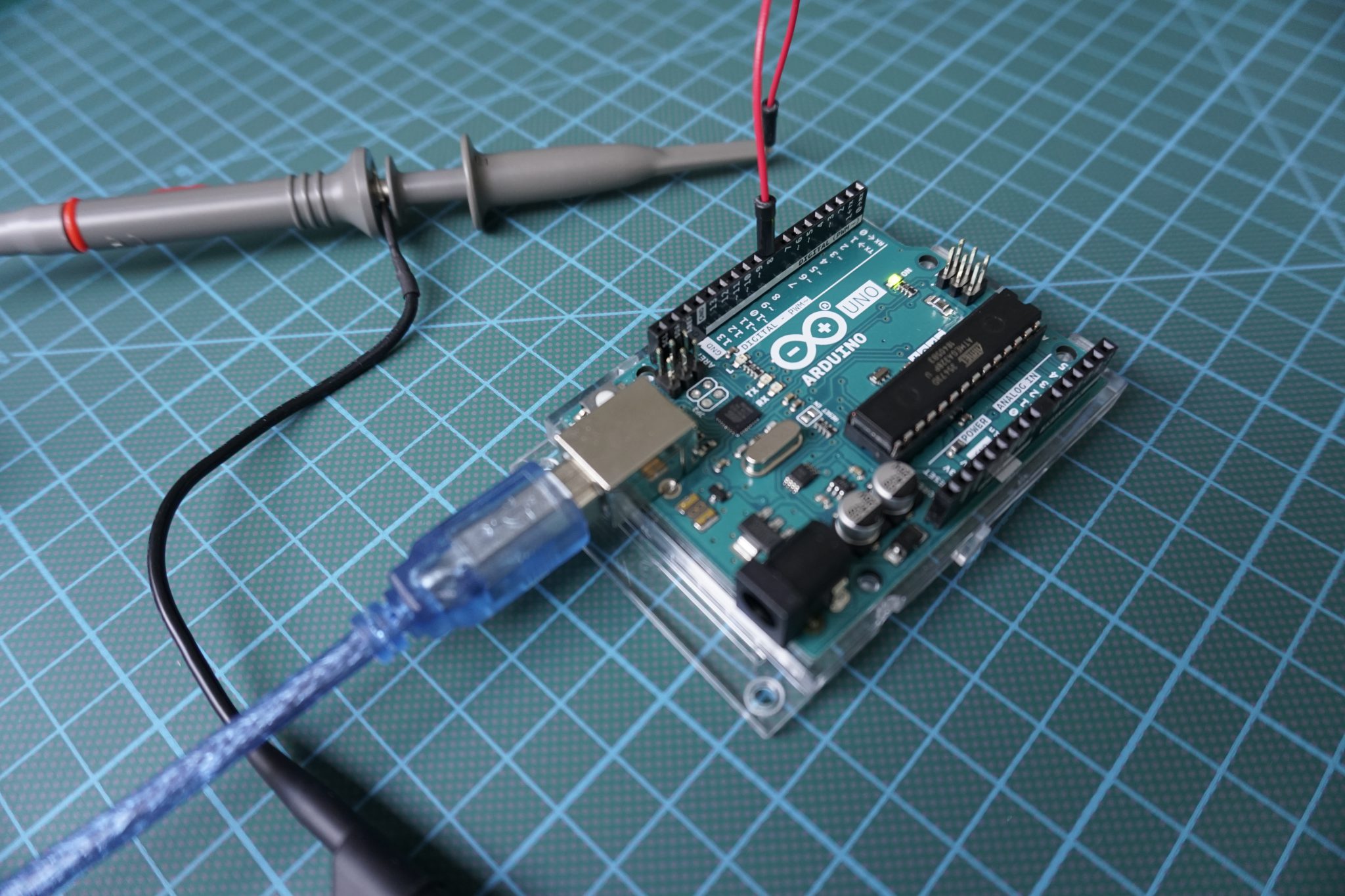
Table of Contents
The objective for Arduino interrupts is to perform a specific task independent of other performed tasks or programs which take place in the setup or loop function. Common examples are:
- Measuring an incoming signal at equally spaced intervals (constant sampling frequency)
- Calculating the time between two events
- Sending out a signal of a specific frequency
- Periodically checking for incoming serial data
There are many task like a for loop or the execution of Arduino libraries which are made up of many commands, where it is not possible to predict the computation time of a single task. Therefore we need a different approach to interrupt the loop function, run a specific task and than continue to execute the loop function.
Depending on your microcontroller, your have multiple timer available to work with. Every timer has a counter which increments the timer on each tick of the timers clock. The ATmega328 which is build on the Arduino Uno has in total 3 timers available. If you do not know what microcontroller is build on your board, you find an overview in this article of the most used boards.
After we know our microcontroller, the following table shows how many timers are available and their size and pin for the connection. Also you find the clock frequency for the chip, which is the fastest speed the timer can increment the counter.
Arduino Interrupts
The often in Arduino boards used ATmega328 chip has in total 3 counters. One of the timer is 16 bit and both others are 8 bit in size. The clock frequency of the chip is 16MHz which means that one tick needs around 63ns.
If you think that this is fast than you are right. Honestly you are more than right because these clock frequency is too fast for interrupts and timed events. The 8 bit timer would be reach the maximum entry in 256/16,000,000s = 16μs and the 16 bit timers in 256/16,000,000s = 4ms.
If we want to interrupt the loop function every second than are these timers not very useful.
But there is a solution called prescaler for this problem. The prescaler is a constant from the values 8, 64, 245, 1024 which reduces the clock speed as a factor:
Speed of timer (Hz) = Clock speed (16MHz) / prescaler
Clear Timer on Compare or CTC Mode
CTC timer interrupts are events which are triggered when the timer reaches a predefined value. This value is stored in the compare match register. At the same time the timer is cleared and set to zero and restarts the counting.
The most used timer registers are the following:
- TCNTx – Timer/Counter Register. The actual timer value is stored here.
- OCRx – Output Compare Register
- ICRx – Input Capture Register (only for 16bit timer)
- TIMSKx – Timer/Counter Interrupt Mask Register. To enable/disable timer interrupts.
- TIFRx – Timer/Counter Interrupt Flag Register. Indicates a pending timer interrupt.
If we want to interrupt every second, the value in the match register is = (clock speed / prescaler * interrupt frequency) -1. We have to subtract 1 because the match register is zero indexed (depends on the microcontroller).
For the ATmega328 with greatest prescaler of 1024, the value of the register would be: (16MHz / 1024 * 1Hz) -1 = 15624. Now we have to choose the timer of that 1Hz second interruption. Timer 0 and Timer 2 can not perform that task because their maximum value to store is 255 with 8bit. Therefor only Timer 1 is able to perform the task 15624<65535.
How to setup the prescalers
The prescalers are setup with different clock select bits. You find the description in the Atmega datasheet. The following tables show the selected bits for the Atmel-7810 as example.
Timer 0
Timer 1
Timer 2
Arduino Interrupt Example
In the following example we want to create a sketch with three different interrupts based on the CTC mode:
- The first timeout at 2kHz toggles Arduino Uno pin 8
- The second timeout at 1Hz toggles Arduino Uno pin 13
- The third timeout at 8kHz toggles Arduino Uno pin 9
The script has the following structure
- Define variables for the toggling
- In the setup function we create the CTC interrupts
- Set the 2 registers TCCRxA and TCCRxB to zero
- Initialize the counter value TCNTx to 0
- Set the value to which the counter value should be compared OCRxA to the following equation: (16*10^6) / (frequency[Hz]*64) – 1
- Turn on the CTC mode
- Setup the prescalers
- Compare the timer for the interrupt
- With the function call sei(); we allow interrupts during the run-time of the microcontroller.
- Define the functions ISR(TIMERx_COMPA_vect) to define what the Arduino should do when the interrupt has taken place. In this example we set the pin HIGH if there is no interrupt and LOW if there is an interrupt. Therefore we are able to verify the behavior of the interrupt with the oscilloscope.
Basically the structure is for all three interrupts the same. Only the frequency when to interrupt has to be adjusted as well as the registers based on their maximal values.
The following script shows the Arduino code, that we discuss step by step.
//storage variables
boolean toggle0 = 0;
boolean toggle1 = 0;
boolean toggle2 = 0;

void setup(){

  //set pins as outputs
  pinMode(8, OUTPUT);
  pinMode(9, OUTPUT);
  pinMode(13, OUTPUT);

cli();//stop interrupts

//set timer0 interrupt at 2kHz
  TCCR0A = 0;// set entire TCCR2A register to 0
  TCCR0B = 0;// same for TCCR2B
  TCNT0  = 0;//initialize counter value to 0
  // set compare match register for 2khz increments
  OCR0A = 124;// = (16*10^6) / (2000*64) - 1 (must be <256)
  // turn on CTC mode
  TCCR0A |= (1 << WGM01);
  // Set CS01 and CS00 bits for 64 prescaler
  TCCR0B |= (1 << CS01) | (1 << CS00);
  // enable timer compare interrupt
  TIMSK0 |= (1 << OCIE0A);

//set timer1 interrupt at 1Hz
  TCCR1A = 0;// set entire TCCR1A register to 0
  TCCR1B = 0;// same for TCCR1B
  TCNT1  = 0;//initialize counter value to 0
  // set compare match register for 1hz increments
  OCR1A = 15624;// = (16*10^6) / (1*1024) - 1 (must be <65536)
  // turn on CTC mode
  TCCR1B |= (1 << WGM12);
  // Set CS12 and CS10 bits for 1024 prescaler
  TCCR1B |= (1 << CS12) | (1 << CS10);
  // enable timer compare interrupt
  TIMSK1 |= (1 << OCIE1A);

//set timer2 interrupt at 8kHz
  TCCR2A = 0;// set entire TCCR2A register to 0
  TCCR2B = 0;// same for TCCR2B
  TCNT2  = 0;//initialize counter value to 0
  // set compare match register for 8khz increments
  OCR2A = 249;// = (16*10^6) / (8000*8) - 1 (must be <256)
  // turn on CTC mode
  TCCR2A |= (1 << WGM21);
  // Set CS21 bit for 8 prescaler
  TCCR2B |= (1 << CS21);
  // enable timer compare interrupt
  TIMSK2 |= (1 << OCIE2A);


sei();//allow interrupts

}//end setup

ISR(TIMER0_COMPA_vect){//timer0 interrupt 2kHz toggles pin 8
//generates pulse wave of frequency 2kHz/2 = 1kHz (takes two cycles for full wave- toggle high then toggle low)
  if (toggle0){
    digitalWrite(8,HIGH);
    toggle0 = 0;
  }
  else{
    digitalWrite(8,LOW);
    toggle0 = 1;
  }
}

ISR(TIMER1_COMPA_vect){//timer1 interrupt 1Hz toggles pin 13
//generates pulse wave of frequency 1Hz/2 = 0.5kHz (takes two cycles for full wave- toggle high then toggle low)
  if (toggle1){
    digitalWrite(13,HIGH);
    toggle1 = 0;
  }
  else{
    digitalWrite(13,LOW);
    toggle1 = 1;
  }
}

ISR(TIMER2_COMPA_vect){//timer1 interrupt 8kHz toggles pin 9
//generates pulse wave of frequency 8kHz/2 = 4kHz (takes two cycles for full wave- toggle high then toggle low)
  if (toggle2){
    digitalWrite(9,HIGH);
    toggle2 = 0;
  }
  else{
    digitalWrite(9,LOW);
    toggle2 = 1;
  }
}

void loop(){
} The following three pictures are screenshots from the oscilloscope, where we can check the frequency of the interrupt. I measured the voltage directly at the output pin of the Arduino Uno. At the bottom of each picture you see that I measured the average of the high pulse width in seconds. If we invert the high pulse width we get the frequency of the interrupt.
Timer0 interrupt at 2kHz
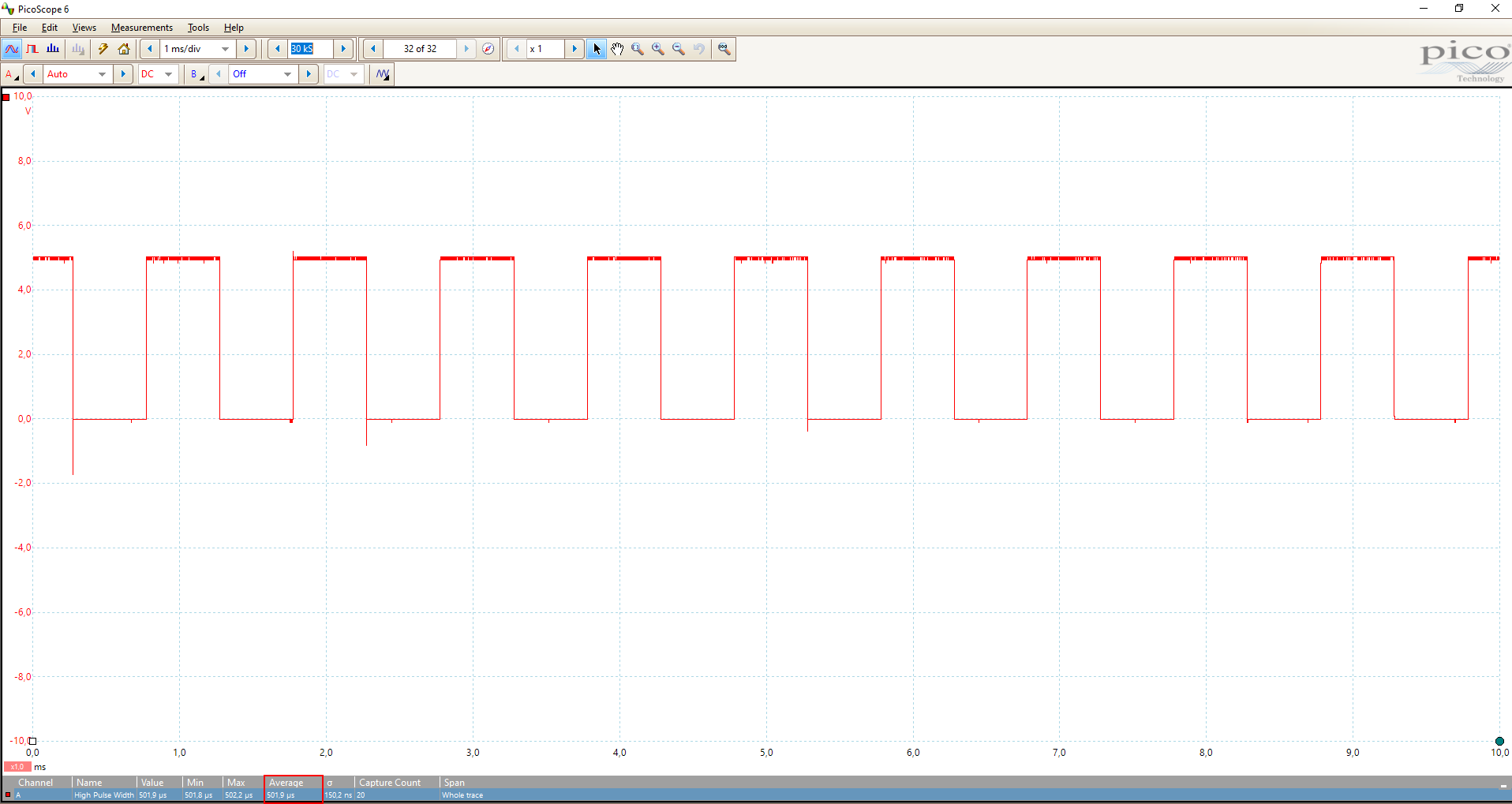
The average high pulse width is 501.9μs with is a frequency of 1.99kHz
Timer1 interrupt at 1Hz
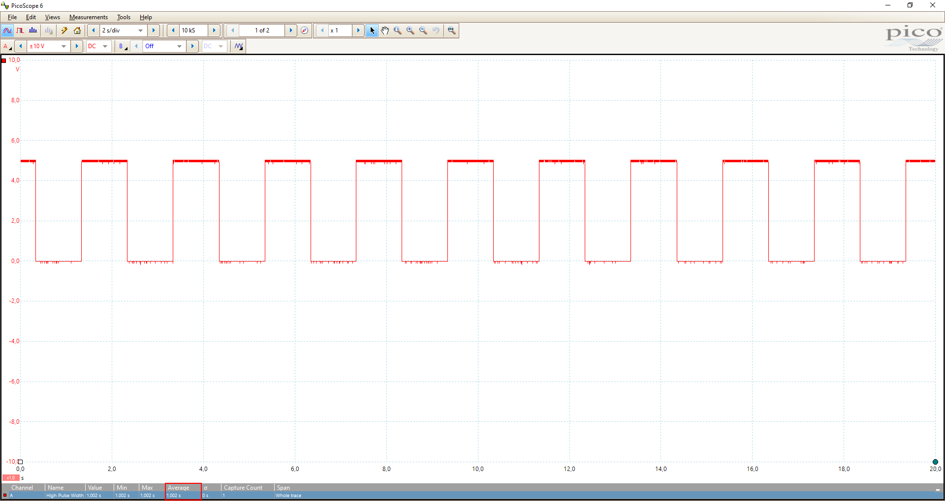
The average high pulse width is 1.002s with is a frequency of 1Hz
Timer2 interrupt at 8kHz
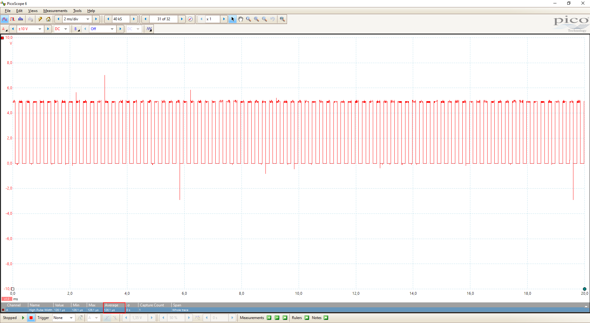
The average high pulse width is 126.1μs with is a frequency of 7.93kHz
Conclusion
In this tutorial we learned a lot about the interrupts and timed events of the Arduino, better said the different ATmega microcontroller. In the example we used only the digital HIGH and LOW function if a timed event takes place. In a real world example we would change the function to something more productive like calculating the time between two events. If you have any questions about this tutorial please use the comment section below.
Sorry to disturb you but I am unable to printout this tutorial
Hi Philippe,
do you mean with printout to save the website as PDF or the serial printout in your Arduino IDE?
Hello Sir,
This is great tutorial.
1. How make 10% duty cycle for every frequency in interrupt timer? toggle pin just make 50% duty cycle. I used delay on interrupt but not really work.
2. What hardware oscilloscope used on this tutorial? can i use audio input for oscilloscope? that is any recommendation for a cheap osciloscope?
Best Regards
Dian
Indonesia