
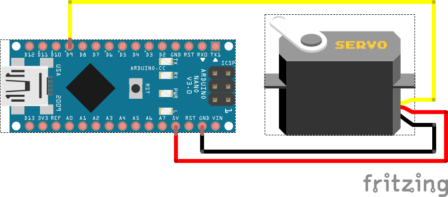
Servo Arduino Nano
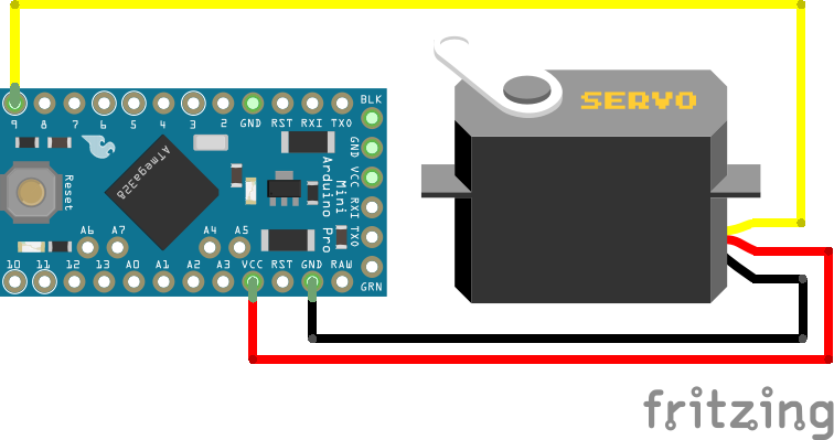
Servo Arduino Pro Mini
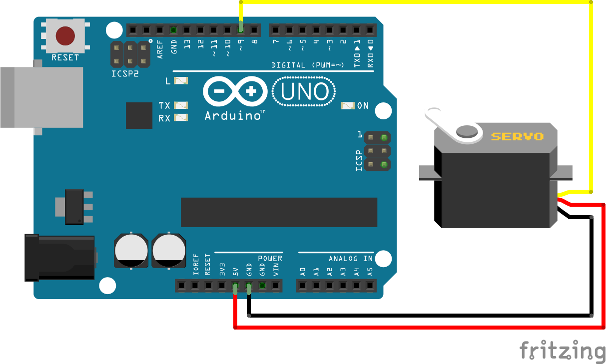
Servo Arduino Uno
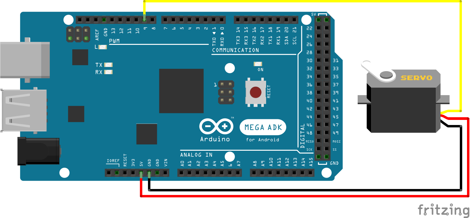
Servo Arduino Mega
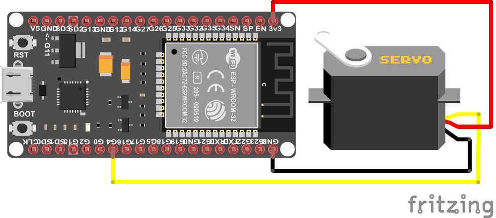
Servo ESP32 NodeMCU
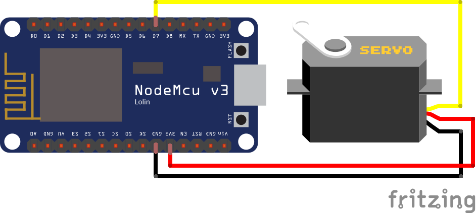
Servo ESP8266 NodeMCU
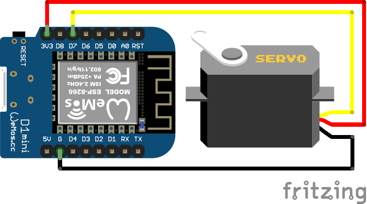
Servo ESP8266 WeMos D1 Mini
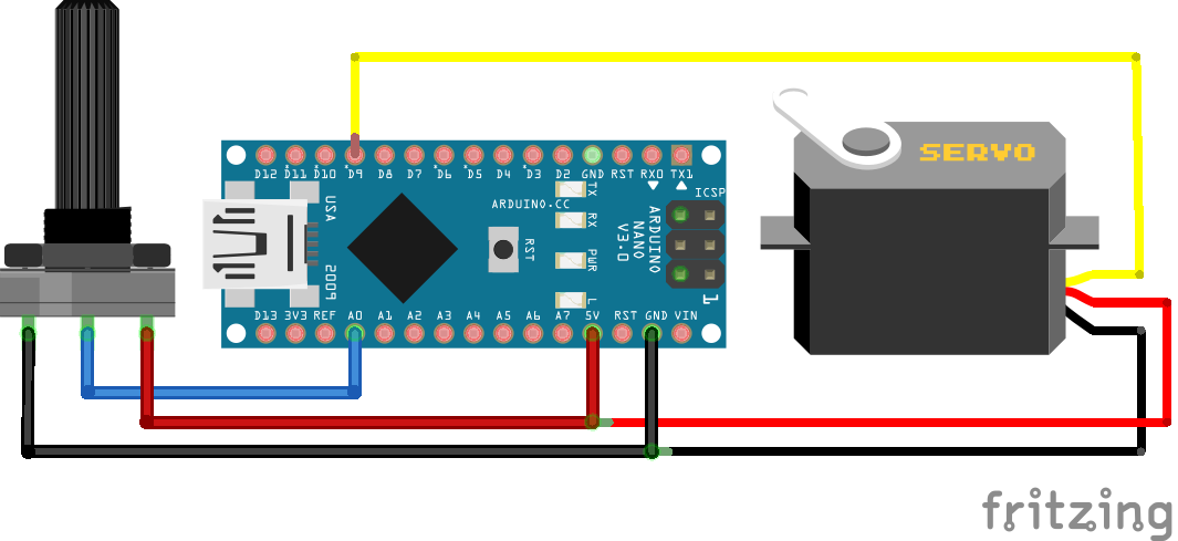
Servo Potentiometer Arduino Nano
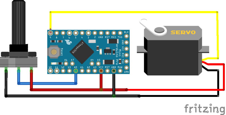
Servo Potentiometer Arduino Pro Mini
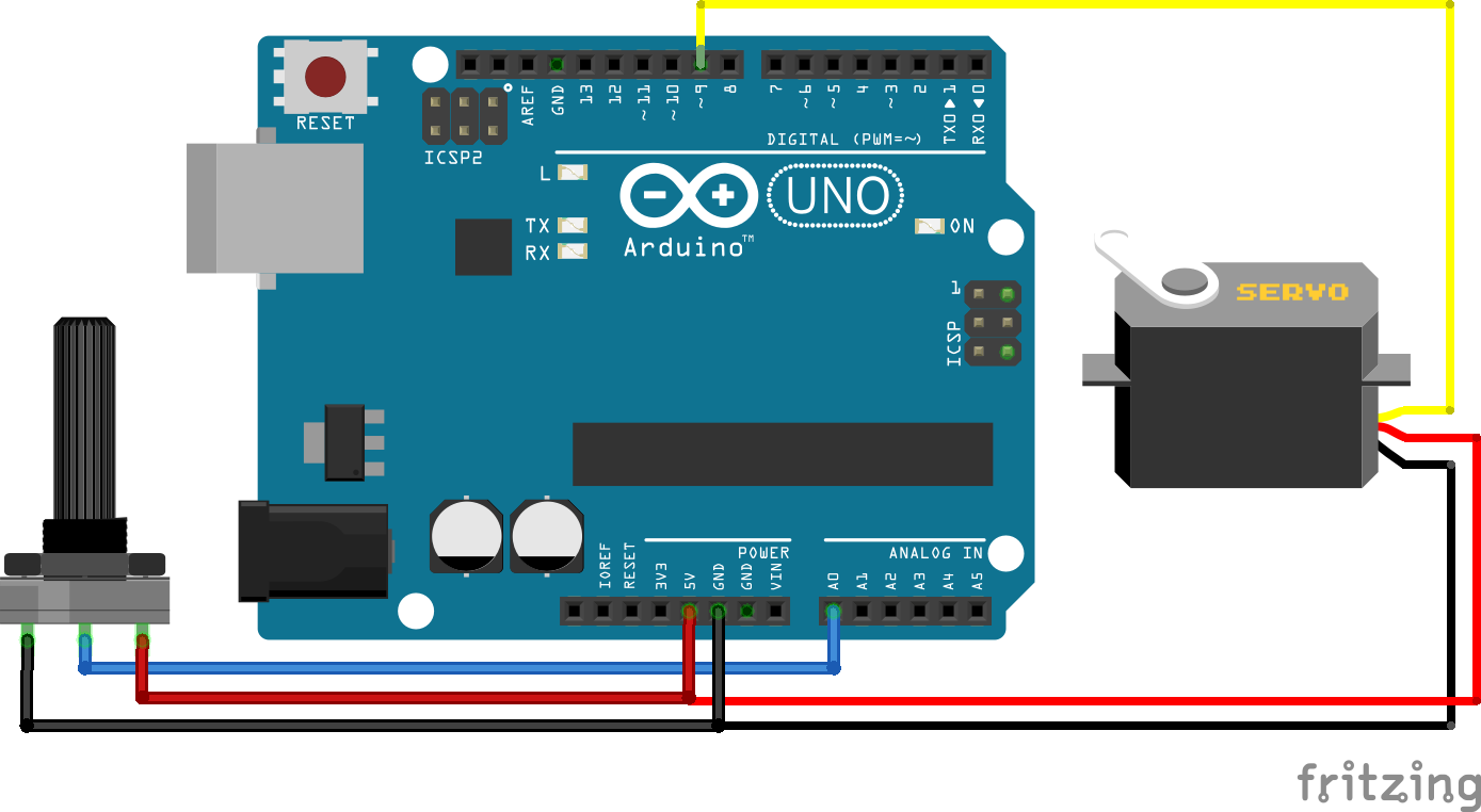
Servo Potentiometer Arduino Uno

Servo Potentiometer Arduino Mega

Servo Potentiometer ESP32 NodeMCU
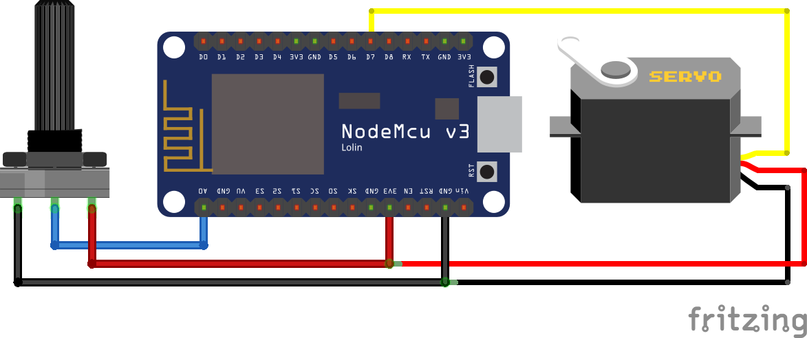
Servo Potentiometer ESP8266 NodeMCU
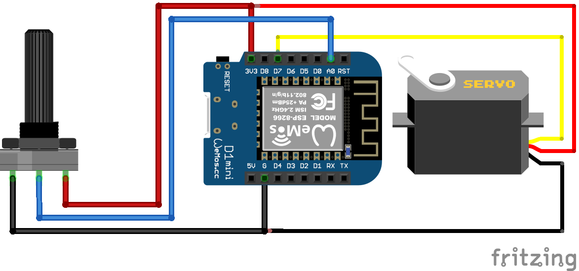
Servo Potentiometer ESP8266 WeMos D1 Mini
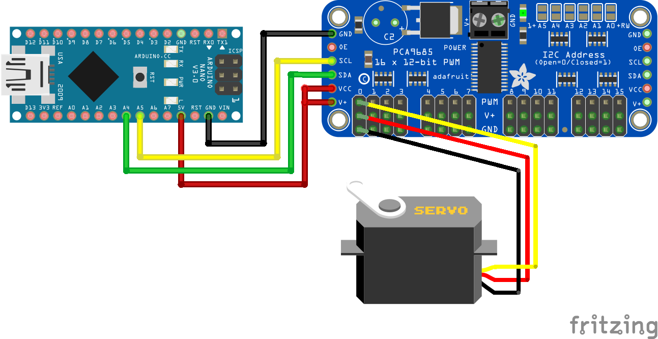
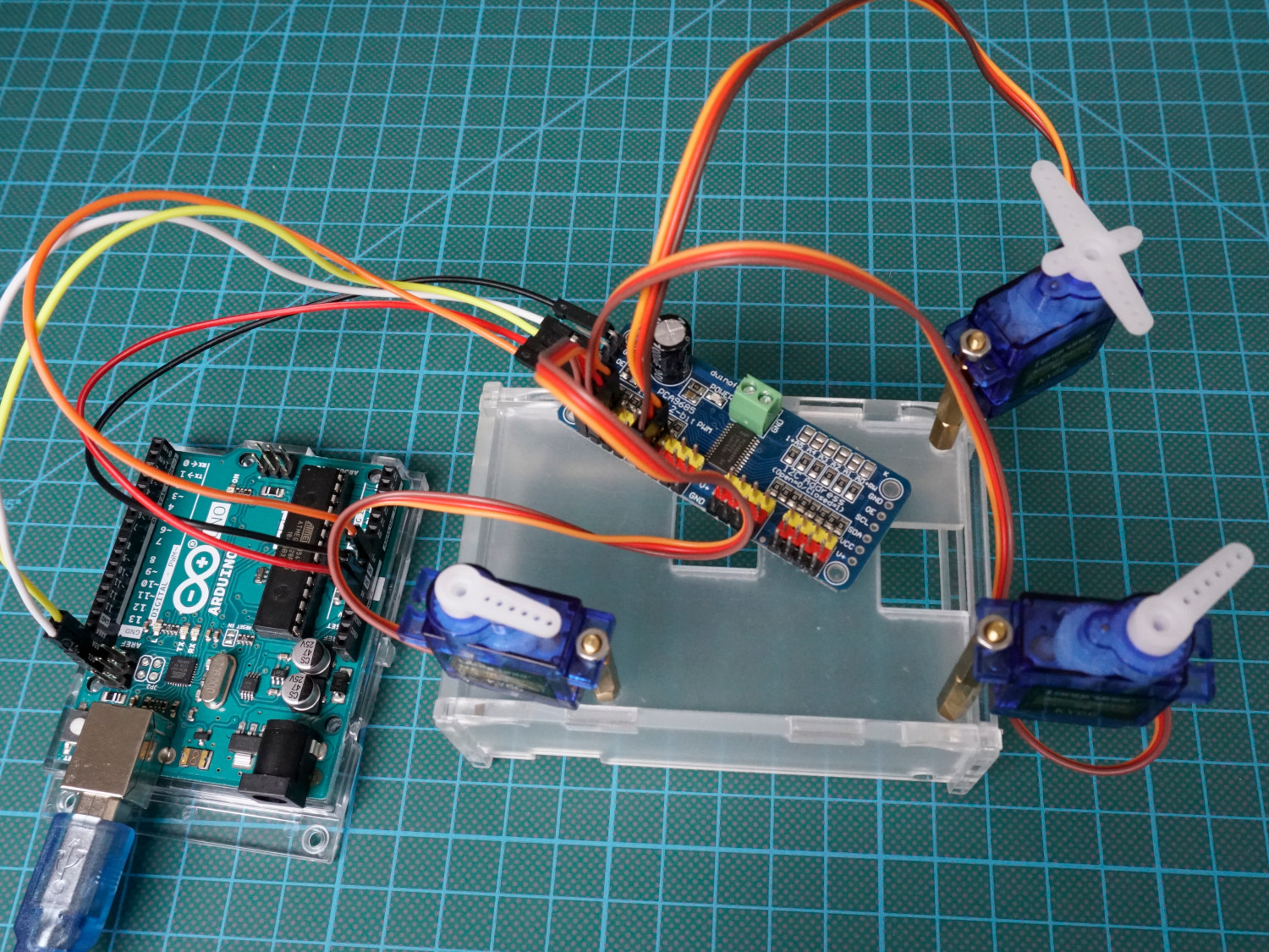
Servo PCA9685 Arduino Nano
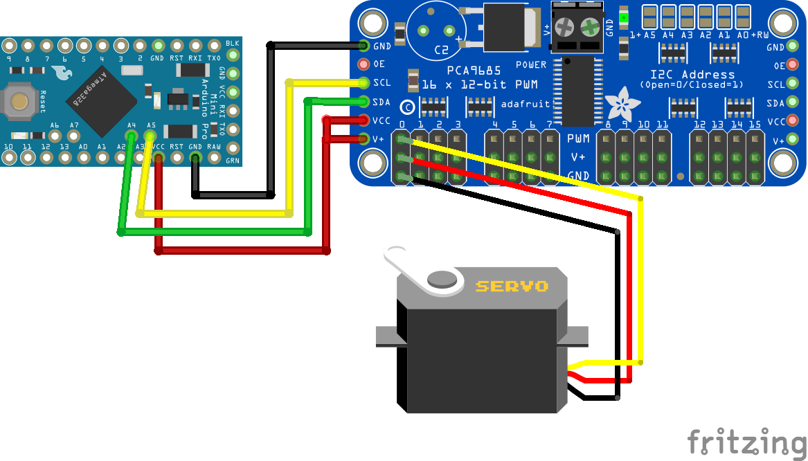
Servo PCA9685 Arduino Pro Mini
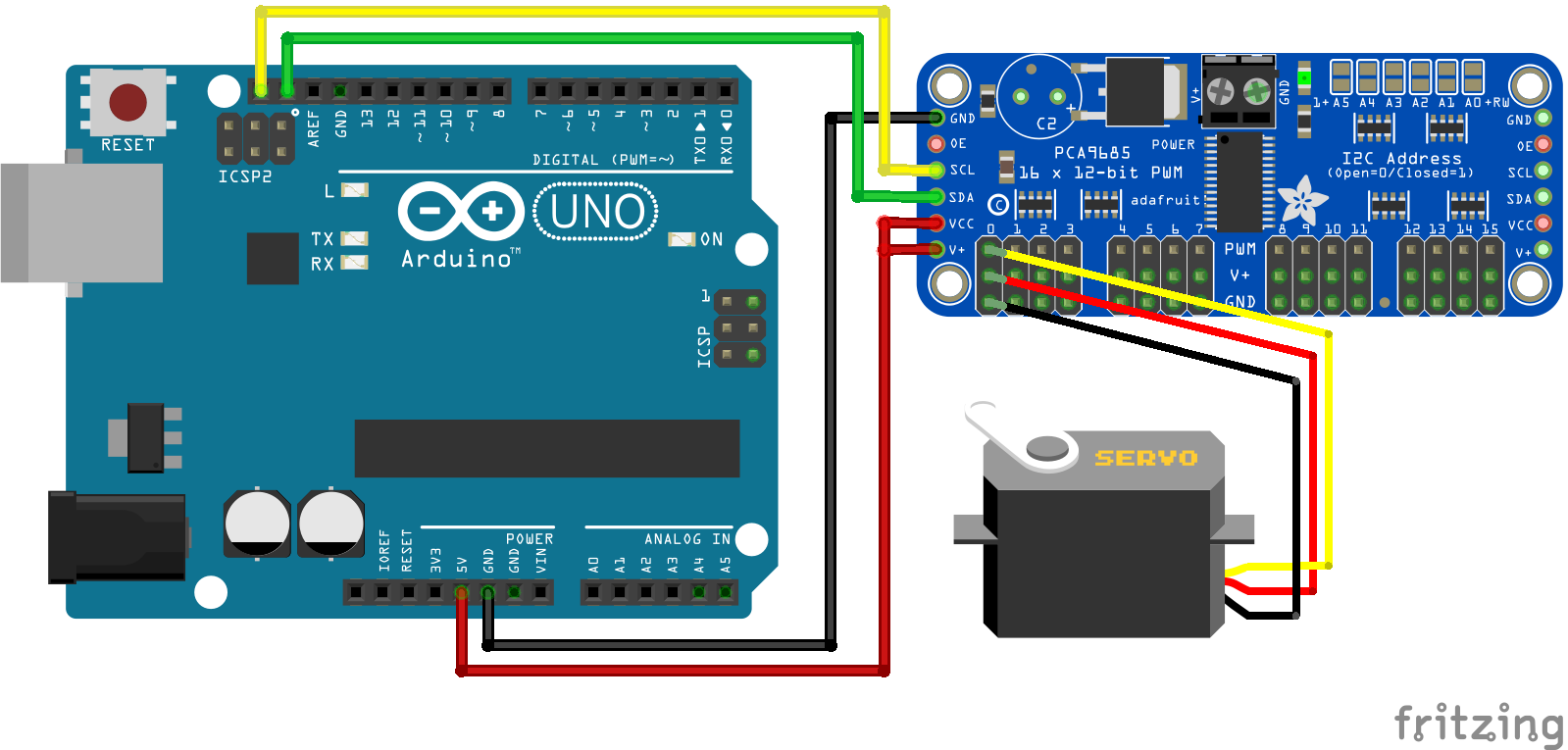
Servo PCA9685 Arduino Uno
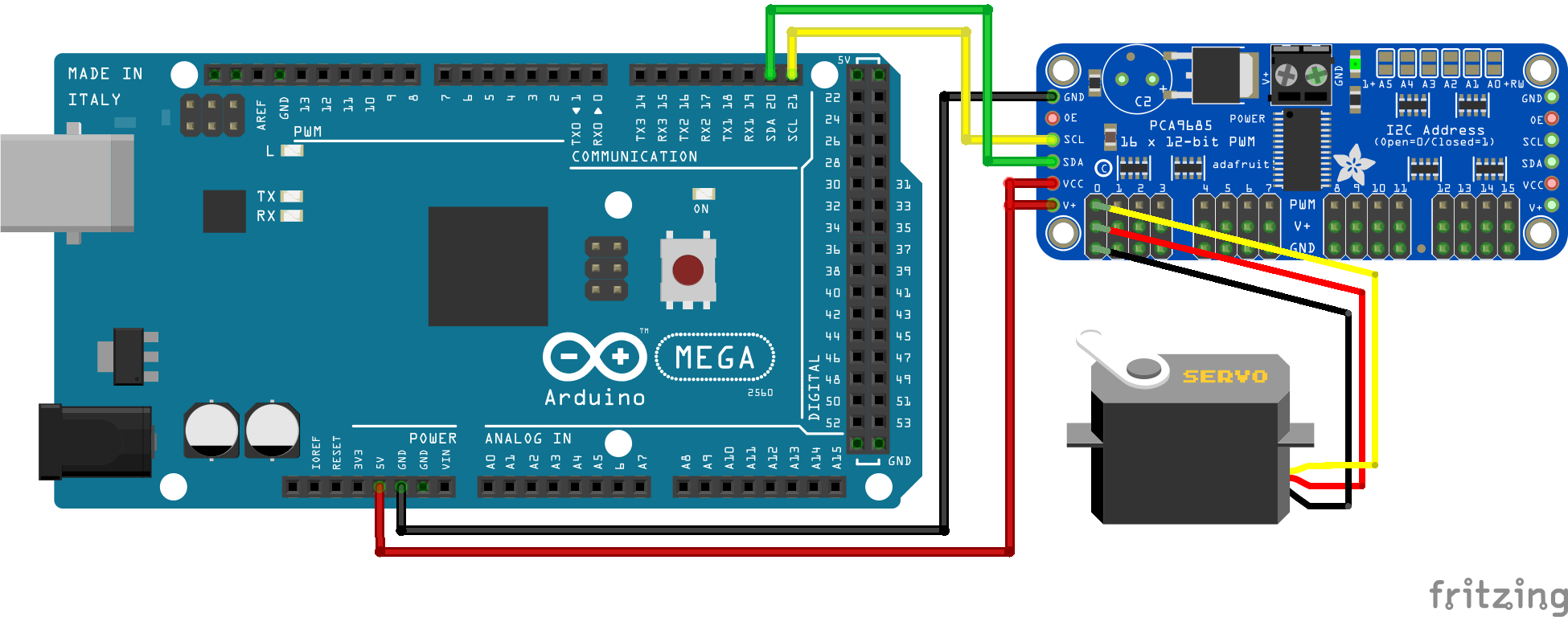
Servo PCA9685 Arduino Mega
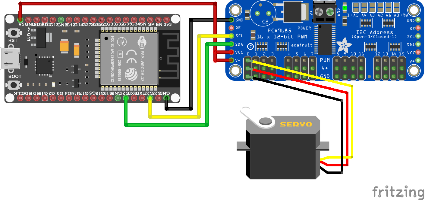
Servo PCA9685 ESP32 NodeMCU
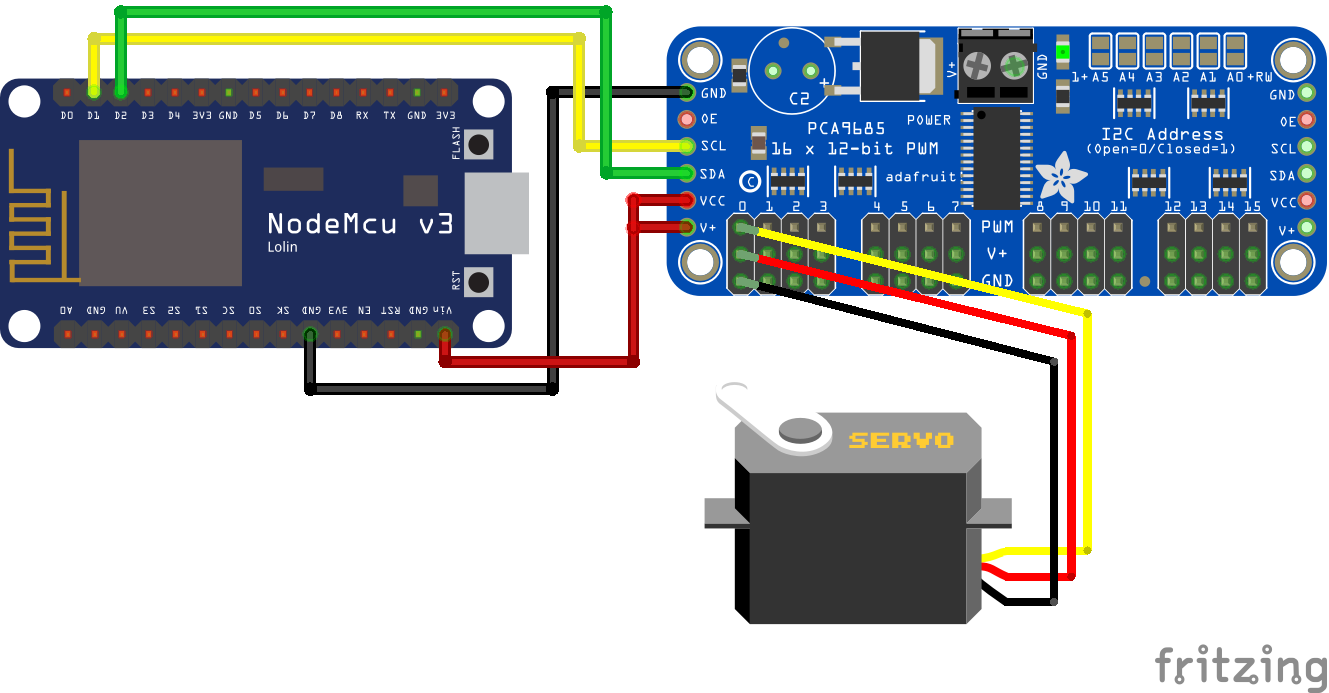
Servo PCA9685 ESP8266 NodeMCU
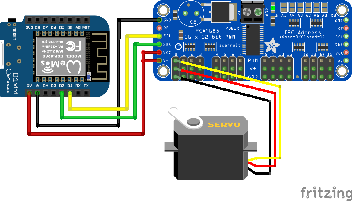
Servo PCA9685 ESP8266 WeMos D1 Mini

Servo PCA9685 External Power Supply Arduino Nano
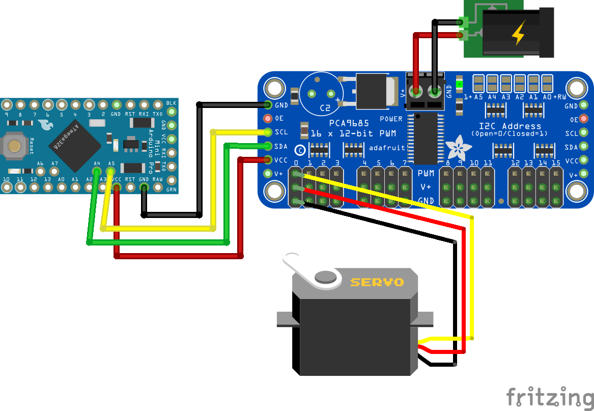
Servo PCA9685 External Power Supply Arduino Pro Mini
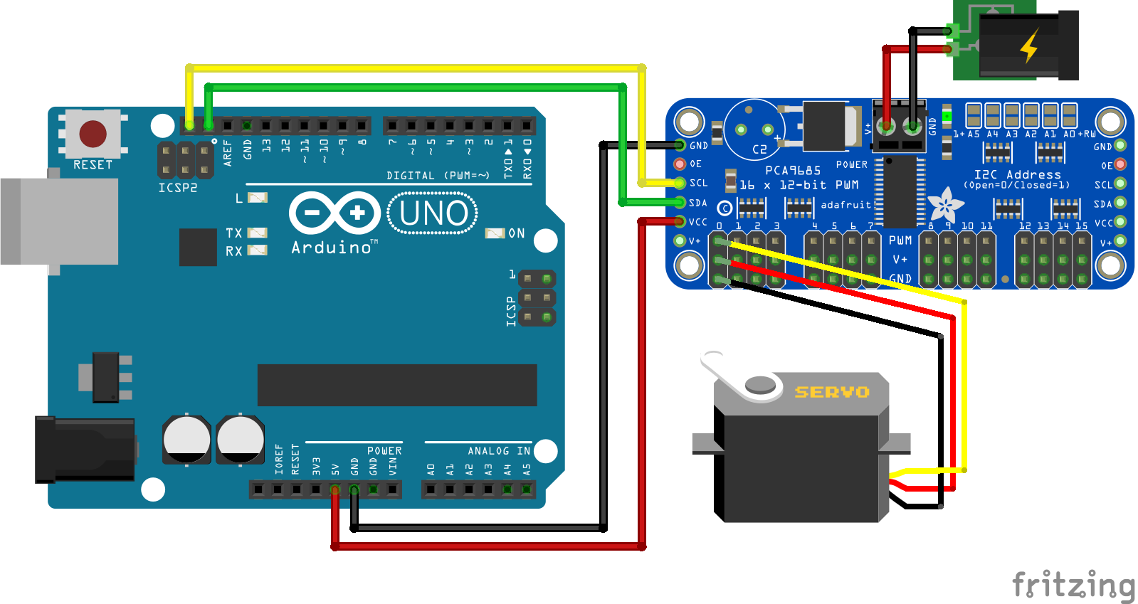
Servo PCA9685 External Power Supply Arduino Uno
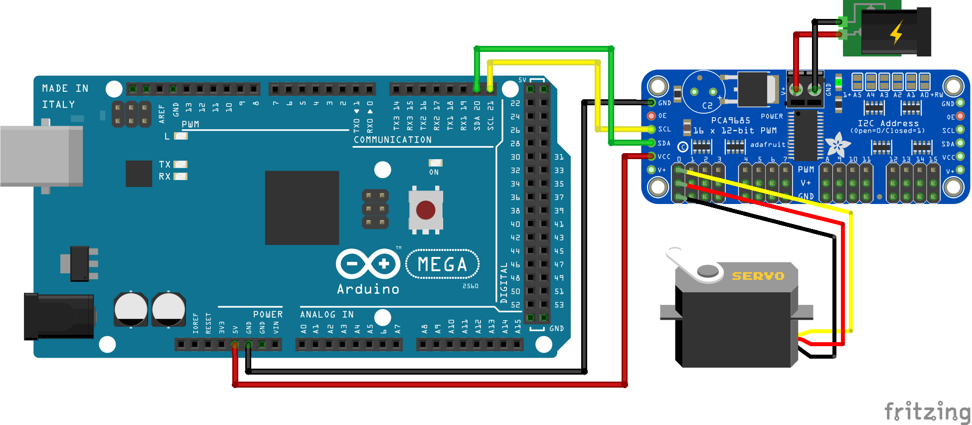
Servo PCA9685 External Power Supply Arduino Mega
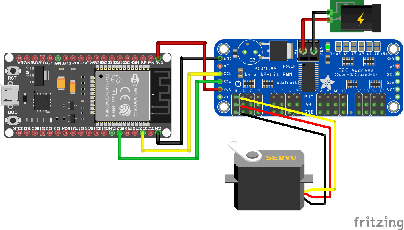
Servo PCA9685 External Power Supply ESP32 NodeMCU
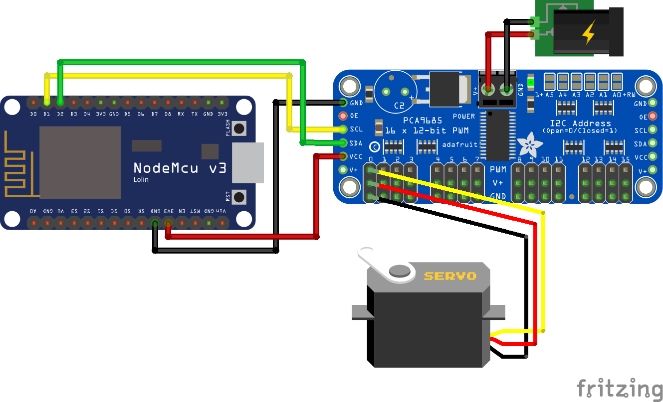
Servo PCA9685 External Power Supply ESP8266 NodeMCU
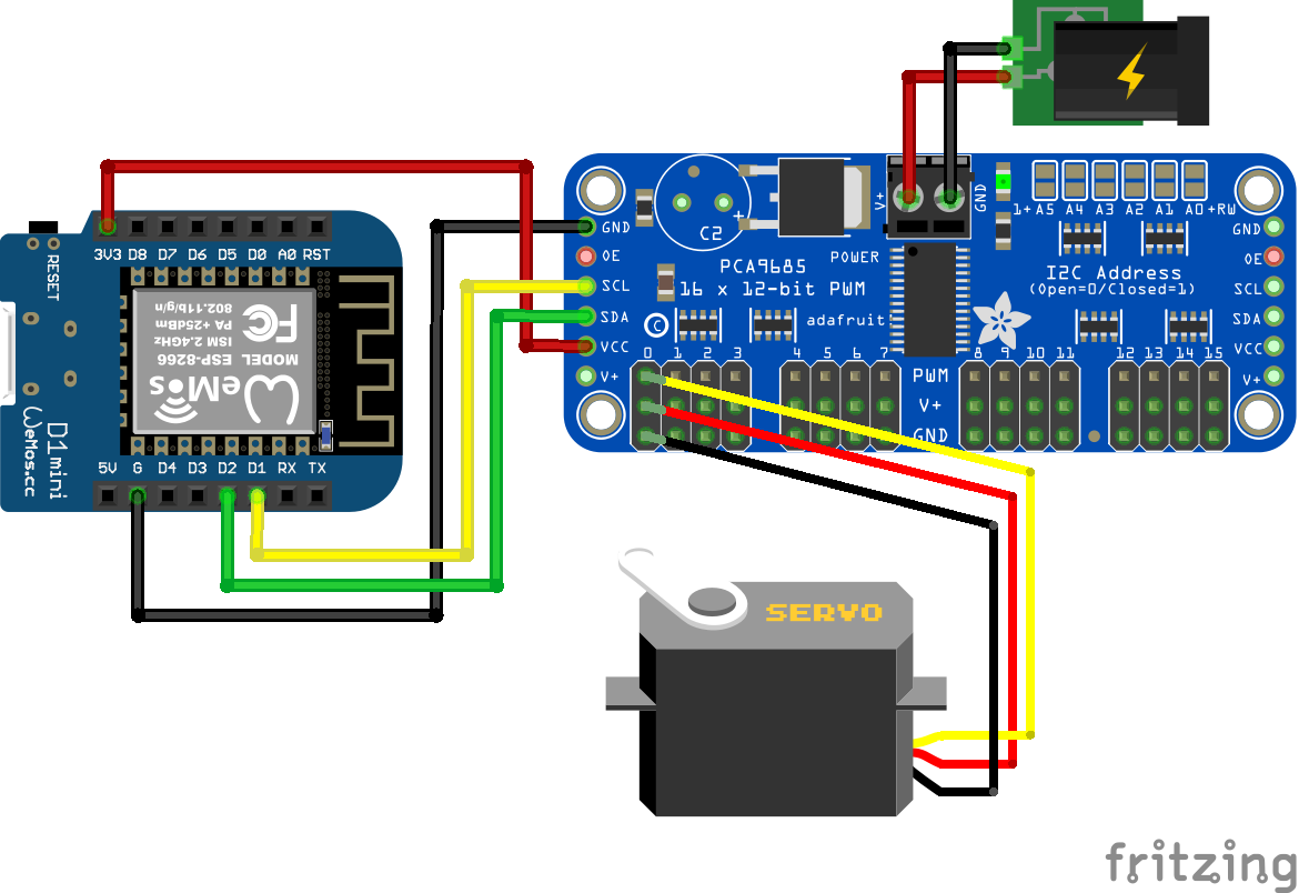
Servo PCA9685 External Power Supply ESP8266 WeMos D1 Mini
Hi
I need help
I’m trying to build a pop-up target with ESP32/esp8266 boards And servo motor and button/switch. This is what I’m trying to build. When the target is hit it will fall and hit the switch and it will restart servo motor to go up 180 degrees Back to 0 Degrees
I’m new at this and I have been working on this for About year. Do you have any idea where I can find a code or diagram For something like this.
Sincerely Buck
Hi Buck,
I hope that I understand your project right: For example you have a metal plate that is connected to the servo motor. If the plate gets hit, the servo motor should turn for 180 degrees and then go back to the original position.
My first question would be how do you sensor that the target was hit?
What does
>#include // include Servo library
do?
Hi Ted, or #include “Servo.h”. For your Arduino code there is no difference but for my WordPress site the first include syntax is recognized as function and not as text. Therefore on my website the library is not shown in the code box.
thanks for your comment because this line of code does nothing, and was a mistake on my side. You can include libraries either with #include
I changed the include code for the whole article and now you see what libraries I include in the examples.
Think you for reply to my question.
This is What I’m trying to make from (YouTube) homemade air soft gun electric target +tinyplan 97.
But use esp32 and esp8266 .
I want to program servos for fingers to move in different positions in a robotic hand. I am using the PCA9685 to run six servos. One servo for the wrist and five for the fingers. Can you do that with the PCA9685? If so, how do you isolate the servos for different movement in the coding. Example: I want the index finger to move just a little and the thumb all the way closed. Can you run servos independently in degrees with the PCA9685?