ESP8266 Tutorial: What do you have to know about the ESP8266 microcontroller?
The following ESP8266 tutorial give you a kick-start in the fundamental knowledge of the ESP8266 microcontroller.
First I show you that the ESP8266 is in my opinion the best microcontroller on the market regarding price-performance ratio. After we compare the pros and cons of the ESP8266, this tutorial will close with a first project as a step by step introduction.
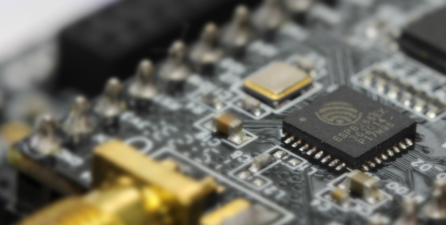
Table of Contents
What is the ESP8266?
The ESP8266 is a powerful 32 bit microcontroller with integrated Wi-Fi and full TCP/IP stack for internet connection. The chip is produced by Espressif Systems in Shanghai, China and is famous for its low price compared to original Arduino boards. You can buy a full ESP9266 board for under $5 which makes it popular for low cost DIY projects. There are different modules using the ESP8266. These modules have a different number of GPIOs to connect the microcontroller with other devices like sensors or actors.
Technical specifications of the ESP8266
- Tensilica’s L106 Diamond series 32-bit processor and on-chip SRAM
- Power supply: 2.5V – 3.6V
- Current consumption: 15µA – 400mA (average: 80 mA). In DeepSleep-Mode only 0.5µA
- Operating temperature range: -40°C – 125°C
- External flash memory: up to 16 MB is supported (512 kB to 4 MB typically included)
- Interfaces
- UART/SDIO/SPI/I2C/I2S/IR Remote Control
- 11 or 13 programmable I/O pins with max current of 12 mA
- 1 analog input 0V to 1V with 10 bit resolution
- all inputs tolerate maximum 3.6V
- Network
- WiFi 802.11 b/g/n 2.4 GHz with WPA/WPA2 PSK
- ipv4 and ipv6 from Arduino Core 2.5.0
- UDP and TCP with 5 simultaneous connections as maximum
- Bandwidth: 150 kByte/s to 300 kByte/s
- Latency: < 10ms
Modules using the ESP8266
There are different modules using the ESP8266. The modules are not really different in programming. If you can program one module, you can basically program all. The main differences are the number and type of ports provided (GPIOs) as well as the available memory. For example, the small ESP-01 module has 512 KB of flash memory and the popular ESP-12E already has 4 MB of flash memory. In this article you find a comparison between all ESP8266 modules because this details are not part of the ESP8266 tutorial.
ESP8266 comparison to Arduino and Raspberry Pi
Advantages
- No special operating system is needed so that the program does not depend on operating system.
- Software is flashed to microcontroller. Therefore the board start executing the script when powered.
- Compared to Arduino boards the ESP8266 are very fast and costs are very cheap.
You find the full comparison between ESP8266 boards and Arduino boards in this article.
Disadvantages
- A special operating system would be more flexible and also use cases like a security camera could be realized faster. See motioneye for Raspberry Pi.
Your first project of the ESP8266
In the following chapter, we will only consider the NodeMCU board which is basically a ESP-12 microcontroller with a voltage regulator and USB-UART interface to flash program code via the Arduino IDE and micro USB cable. Also the NodeMCU fits on breadboards which makes it easier and faster to build a prototype without soldering.
The following table gives you an overview of all components and parts that I used for this tutorial. I get commissions for purchases made through links in this article.
- NodeMCU (Amazon) (Banggood)
- Pin Jumper Wires (Male to Male) (Amazon) (Banggood)
- Breadboard (Amazon) (Banggood)
- LED (Amazon) (Banggood)
Now lets go into the practical part of this ESP8266 tutorial. We will make our first project. Follow the following 5 steps:
1) First you have to buy your ESP8266 board
To start the practical part of this ESP8266 tutorial you have to own an ESP8266 board. You can find a link to Amazon and Banggood in the box above. The NodeMCU is quite cheap and if you want to make more projects in the future you can directly buy a bundle of 4 boards to save some money. Also if you don’t have any of the needed components you can buy a Starter Kit. Trust me, you will need almost every part of such a kit in the future.
2) Second install and configure the Arduino IDE
We want to use the Arduino IDE as development platform to write and upload programs to compatible boards. You can download the Arduino IDE from the official website.
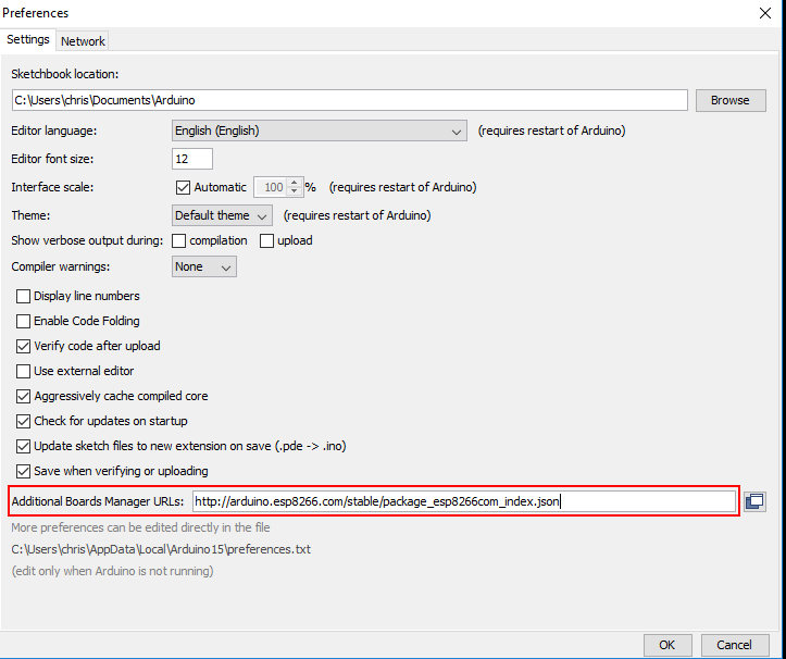
I suggest to use the latest version of the Arduino IDE. You can download and extract the zip file. There is no need for an installation, just open the Arduino IDE by clicking on arduino.exe. The Arduino IDE supports a whole range of different Arduino boards. Since we do not want to use an Arduino board but the NodeMCU board, we have to introduce the NodeMCU board to the IDE. This is quite easy. Just click on File → Preferences. Insert the following URL for the Additional Board Manager URLs.
http://arduino.esp8266.com/stable/package_esp8266com_index.json
3) Program the first script
Our first script will be a flashing LED and easy to program with only a few lines of code. The programming language is based on C. It is also possible for the ESP8266 to use LUA as programming language, but I prefer scripting in C. Every Arduino script is basically divided up into 3 parts:
- In the first part, variables and constants are defined. In this first part we define the GPIO pin connecting to the anode of the LED.
- The second part is the setup function. This function will run only one time if the ESP8266 is connected with a power supply. In our ESP8266 tutorial script we will define the selected GPIO pin as output.
- The last part of the script is the loop function, which will run as an open ended loop for the microcontroller. In the last part of the script we turn on the LED with the function digitalWrite(ledPin, HIGH) and wait a defined period of time. After this we, turn off the LED with the same function only that we change the command from HIGH to LOW and wait again for a while.
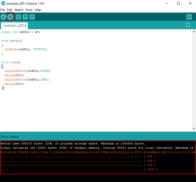
The following part is the finished script. Feel free to copy the script to your Arduino IDE.
const int ledPin = D8;

void setup()
{
  pinMode(ledPin, OUTPUT);
}

void loop()
{
  digitalWrite(ledPin,HIGH);
  delay(200);
  digitalWrite(ledPin,LOW);
  delay(200);
}
4) Connect all parts on a breadboard
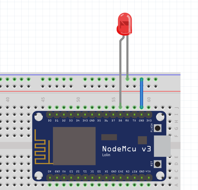
Connecting all parts is easy because we only have one LED component. We define, that the LED will be powered from GPIO Pin D8 because we have to select a digital output for the LED. If you want to change the GPIO Pin, feel free but you have to use one of the digital outputs D1 to D8. If you change the GPIO Pin, make sure to change the script. Now connect all the parts:
- Put the NodeMCU on the breadboard and make sure there is one line of space to connect the LED.
- Connect the positive pole of the LED (long leg) with D8 of the ESP8266. In the breadboard, the vertical rows of the upper and lower side are interconnected internally.
- Connect the negative pole of the LED (short leg) with ground (GND) of the ESP8266.
Note: Typically the forward voltage of an LED is between 1.8 and 3.3 volts and the operating voltage of the ESP8266 is 3.3V. Therefor we do not need to use a resistor in series to the LED. If you are using a Arduino board, the operating voltage is 5V and you will need a 220 Ohm resistor.
5) Upload and run the script to the ESP8266 board
Now it is time to upload the script to the ESP8266. But first we have to make sure that all settings for the upload fit to the ESP8266.
You check the settings by connecting your NodeMCU via Micro USB to your PC or Laptop.
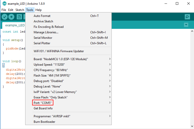
Click in the Arduino IDE on Tools and make sure your settings are the following. To select the Node MCU Board the Ardiuno IDE has to download the board information from the Board Manager: Click on Tools → Board → Board Manager.
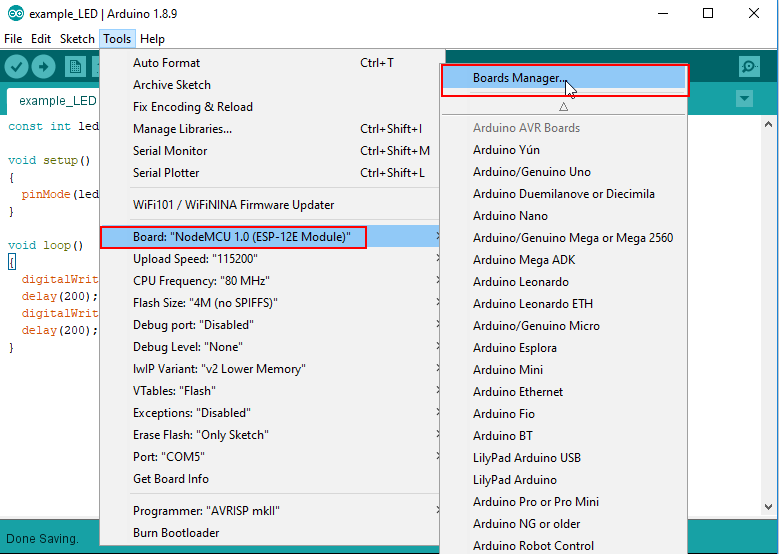
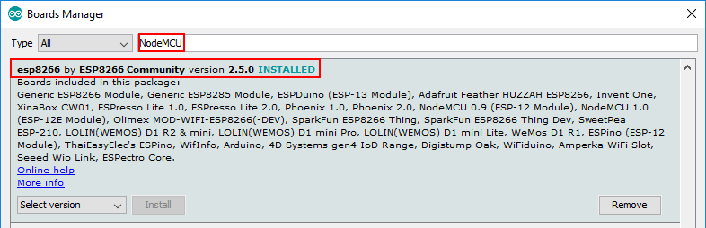
After the Arduino knows the ESP8266 boards make sure your settings for the board are the same as the following table
| Board | NodeMCU 1.0 (ESP-12E Module) |
| Upload Speed | 115200 |
| CPU Frequency | 80 MHz |
| Flash Size | 4M (1M SPIFFS) |
| Debug port | Disabled |
| Debug Level | None |
| IwIP Variant | V2 Lower Memory |
| Erase Flash | Only Sketch |
| Port | Your port number depend on you USB ports. There have to be one COM port able to select. |
I hope you enjoyed this ESP8266 tutorial. You learned the fundamental knowledge of the ESP8266 microcontroller with the technical specifications. Also you know that there are different boards using the ESP8266 and created you first project with my favorite boards, the NodeMCU.
Now it is your part to make some changes to the script. Practices is the best method to get you familiar with the whole topic of microcontrollers. For example you can change the pause time up and down or use an other digital output as power source for the LED.
If you have questions, feel free to leave a comment.
Conclusion
In this article you learned the basics about the ESP8266 microcontroller. You know the technical specifications and the differences between ESP8266 boards, Arduino boards and the Raspberry Pi. Also I hope that you enjoyed creating your first project.
What do you think about the ESP8266? Do you like this microcontroller or do your prefer the Arduino or the Raspberry Pi? Also I would like to know what are projects you will implement.
Leave A Comment