Resistor Tutorial for Arduino, ESP8266 and ESP32
In this article we cover different kinds of resistors like:
- Photoresistors
- Potentiometer
- Thermistors
Also we will look deeper in the functionality of the voltage divider which gives us a basic understanding how these different kinds of resistors work.
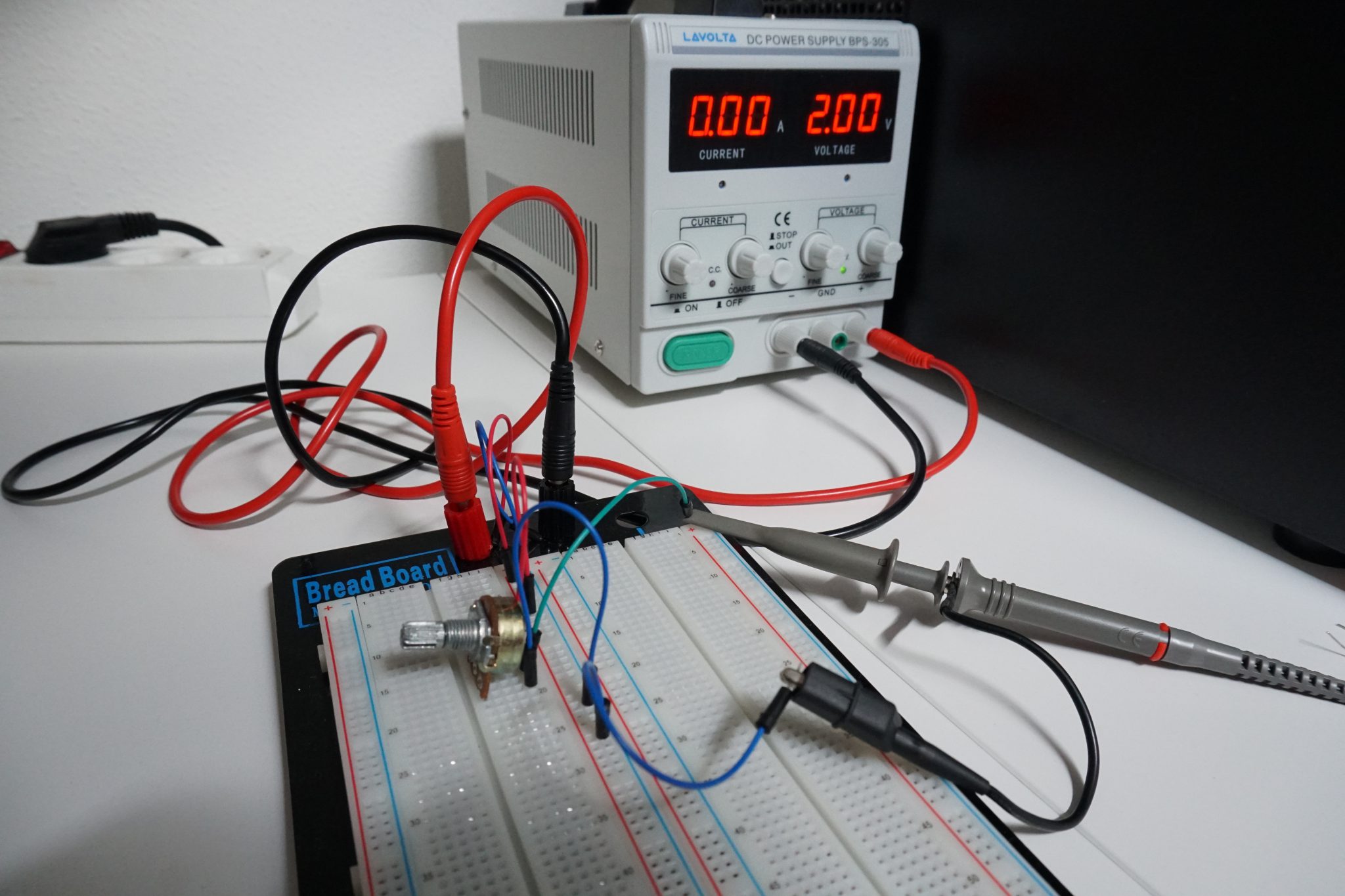
Table of Contents
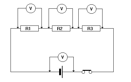
Voltage Divider
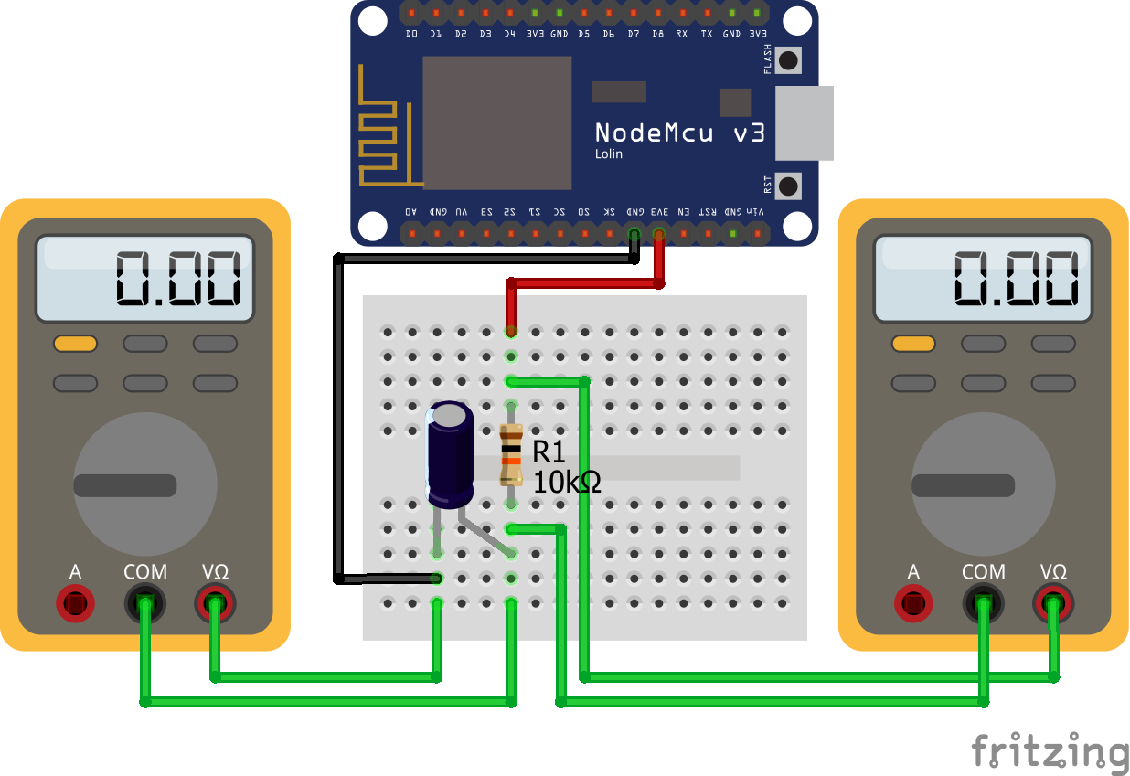
The objective of a voltage divider is to change the output voltage with the combination of 2 resistors.
One example of the use of a voltage divider is the light dependent resistor, see the second chapter in this article. Another example is a potentiometer to control the speed of a motor for example. The following example reduces the input voltage of 5V to an output voltage of 3.3V and uses a voltage divider for this task.
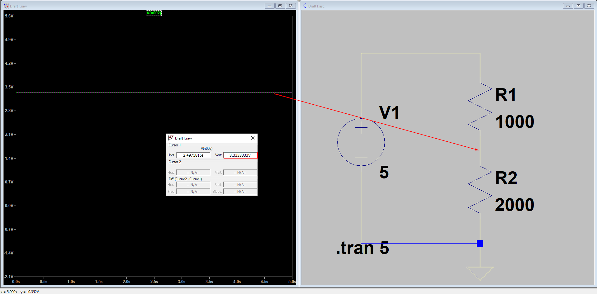
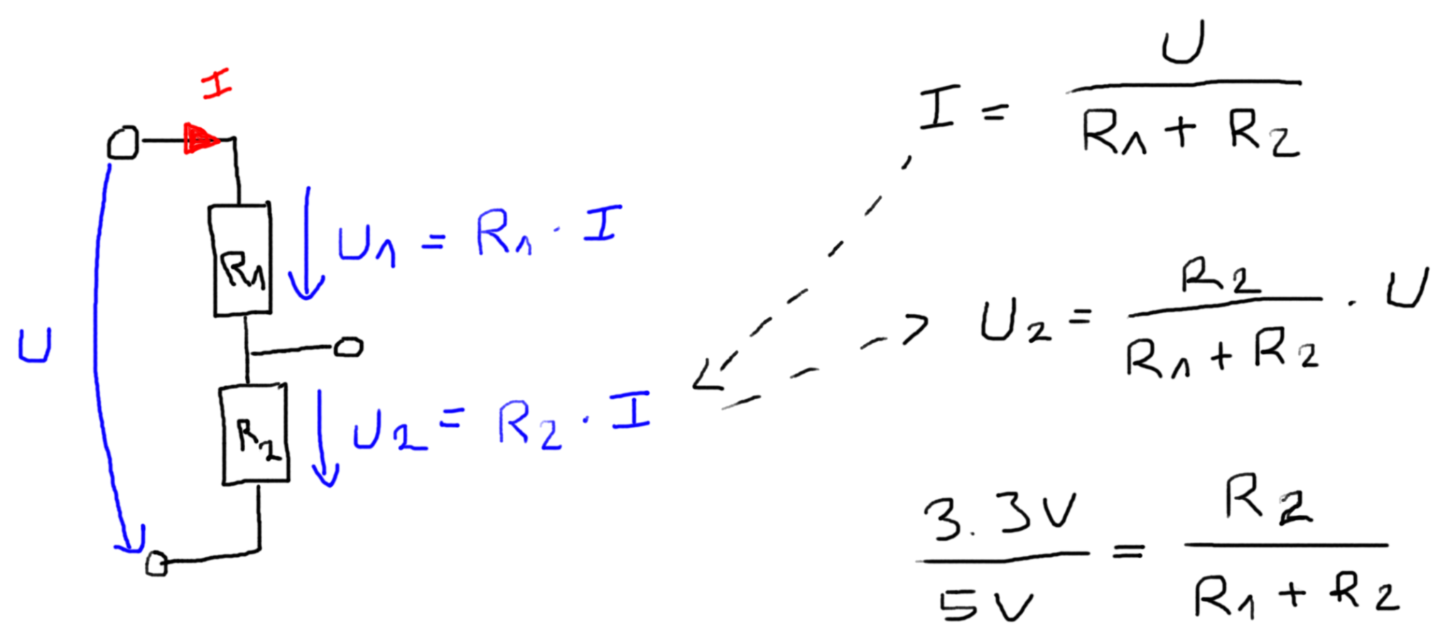
The equation to calculate the output voltage from a voltage divider is given by: U2 = U* (R2/(R1+R2)). If the objective is to reduce the voltage from U=5V to U2=3.3V than multiple solutions are possible:
- R1=1kΩ and R2=2kΩ
- R1=5kΩ and R2=10kΩ.
So how do we choose the right combination? The solution is that the power to reduce the voltage and therefore the corresponding heat is not the same. The power is defined as P = U^2/(R1+R2). That’s why the combination of 5kΩ and 10kΩ resistors are producing less heat and are the preferable choice.
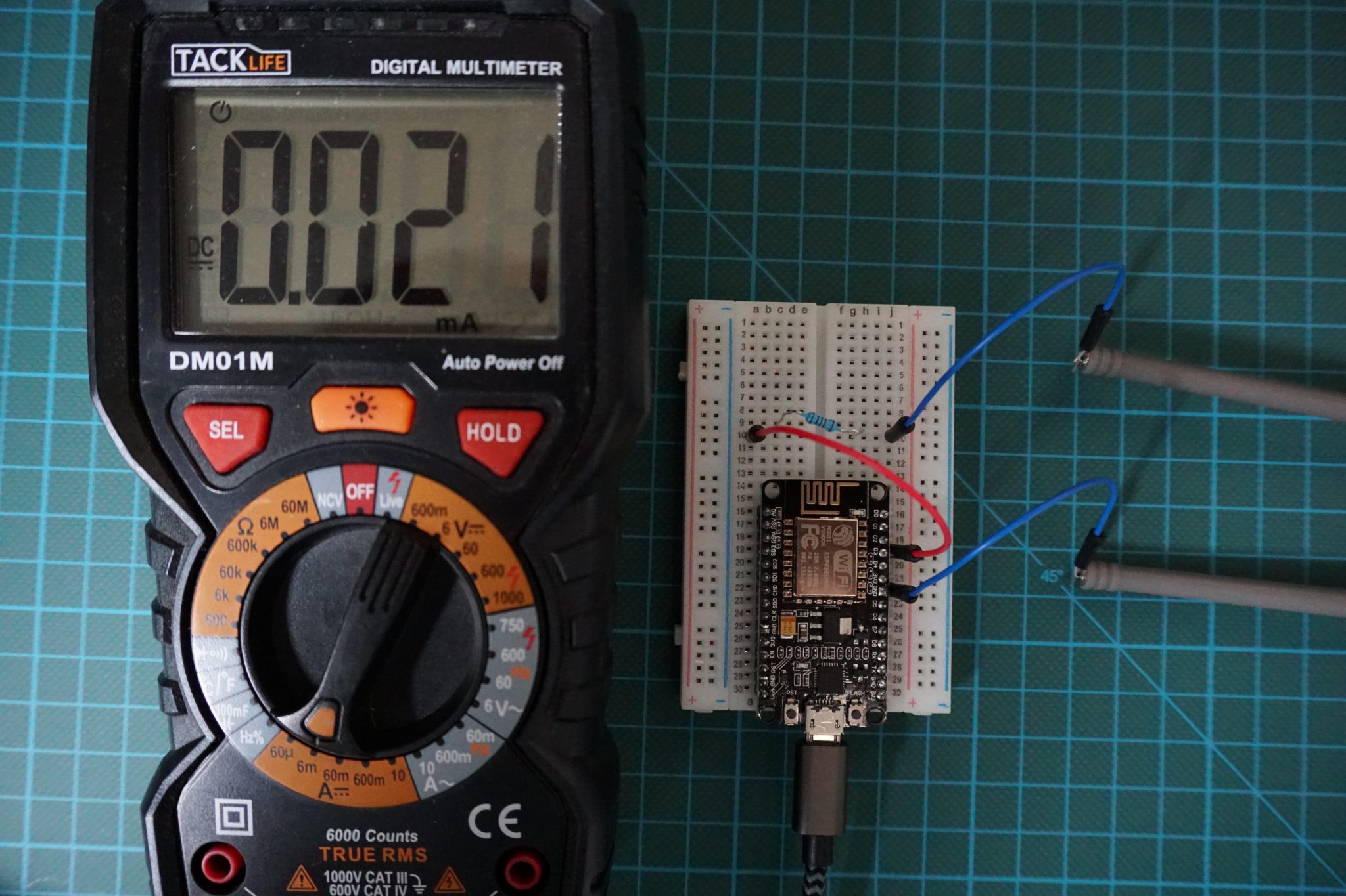
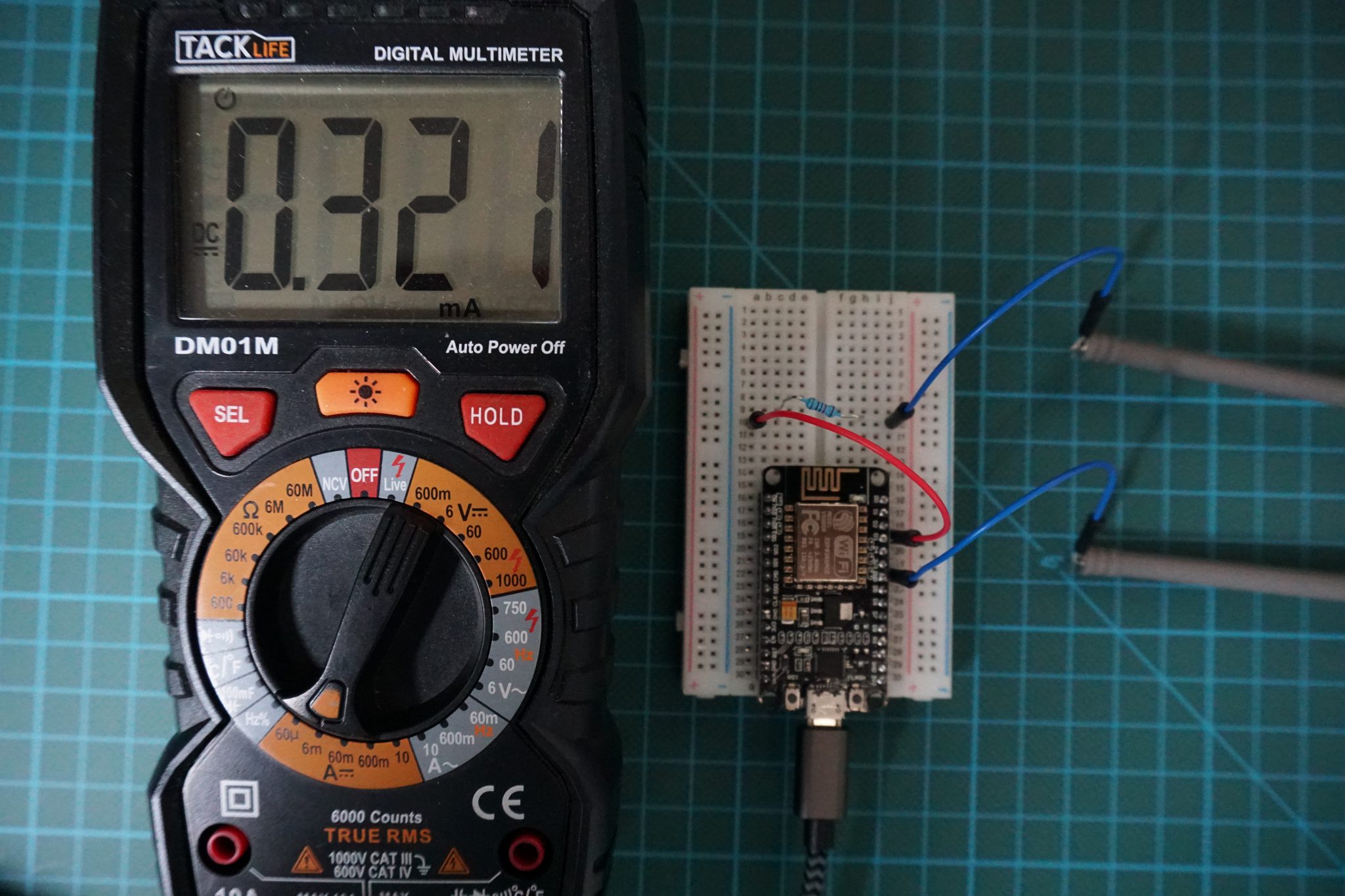
Keep in mind not to use a voltage divider to reduce the voltage to supply a device or load because you have to remember that an external device will result in a parallel circuit with R2. The following example show the differences in the decision to choose the resistors for the voltage divider.
| R1 | 5000Ω | 50Ω | |
| R2 | 10000Ω | 100Ω | |
| Resistance external device | 66Ω | 66Ω | |
| U | 5V | 5V | |
| R2 || Resistance external device | R2*External device / (R2 + External device) | 65.57Ω | 39.76Ω |
| U2 | U2 = U * (R2||External device/(R1+R2||External device)) | 0.07V | 2.22V |
| P | U^2/(R1+R2||External device) | 4.94 mW | 278.52 mW |
In the example you could reduce the voltage from 5V to 2.22V with the combination of R1=50Ω and R2=100Ω but your output power with 278.52 mW will likely burn the resistors.
The following table gives you an overview of all components and parts that I used for this tutorial. I get commissions for purchases made through links in this table.
| Arduino Uno | Amazon | Banggood | AliExpress | |
| OR | ESP8266 NodeMCU | Amazon | Banggood | AliExpress |
| OR | ESP32 NodeMCU | Amazon | Banggood | AliExpress |
| AND | Photoresistor | Amazon | Banggood | AliExpress |
| AND | Potentiometer | Amazon | Banggood | AliExpress |
| AND | Thermistor | Amazon | Banggood | AliExpress |
Photoresistor
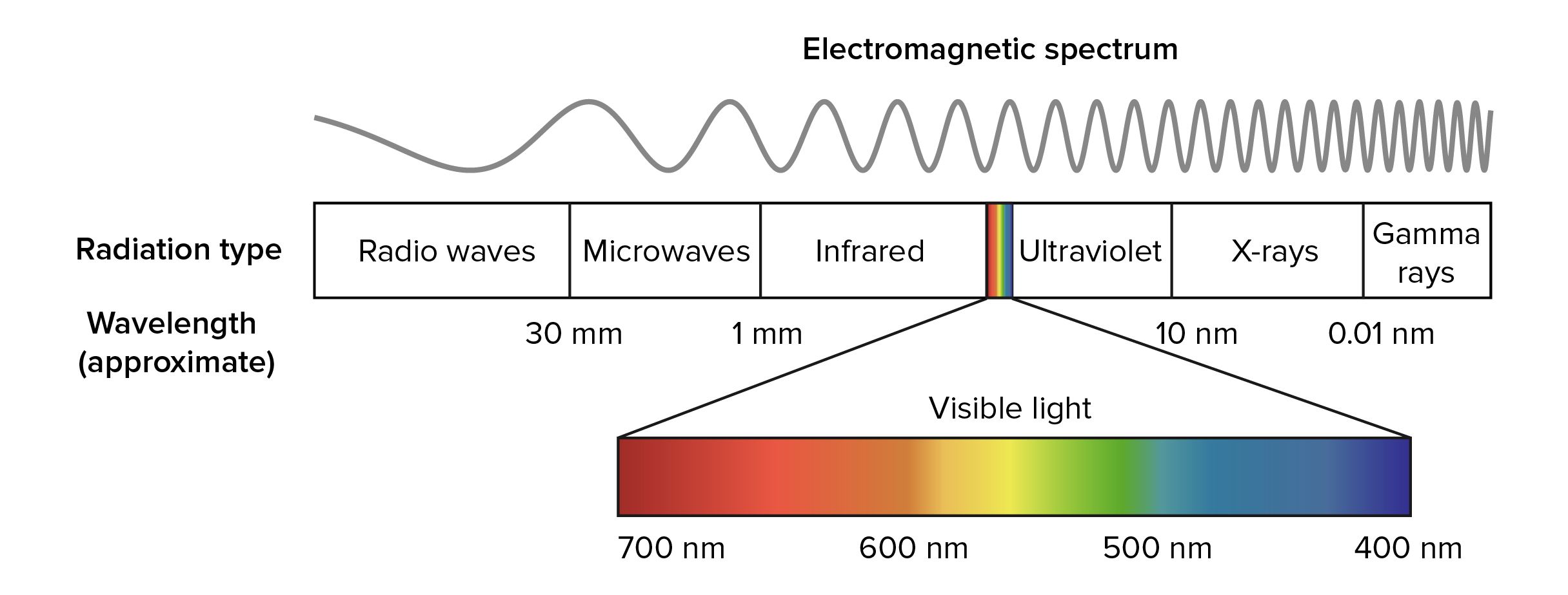
The photoresistor, often called light dependent resistor (LDR) or light sensor, is a resistor which
changes his resistance based on the incident light.
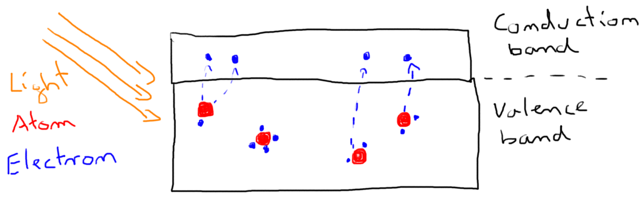
The photoresistor contains electrons which are bonded to atoms in the valence band. If light falls on the photoresistor the electrons in the valence band, called valence electrons, absorb energy from the light and break the bond with the electrons. The electrons which break the bond are called free electrons and will jump into the conduction band. In the conduction band the electrons, not bonded to any atom are able to freely move from one place to another.
On the other side the atoms which previously had more electrons are now called holes. Therefore free electrons and holes are created as pairs and are carry electric current. These electric current decreases the resistance from the photoresistor.
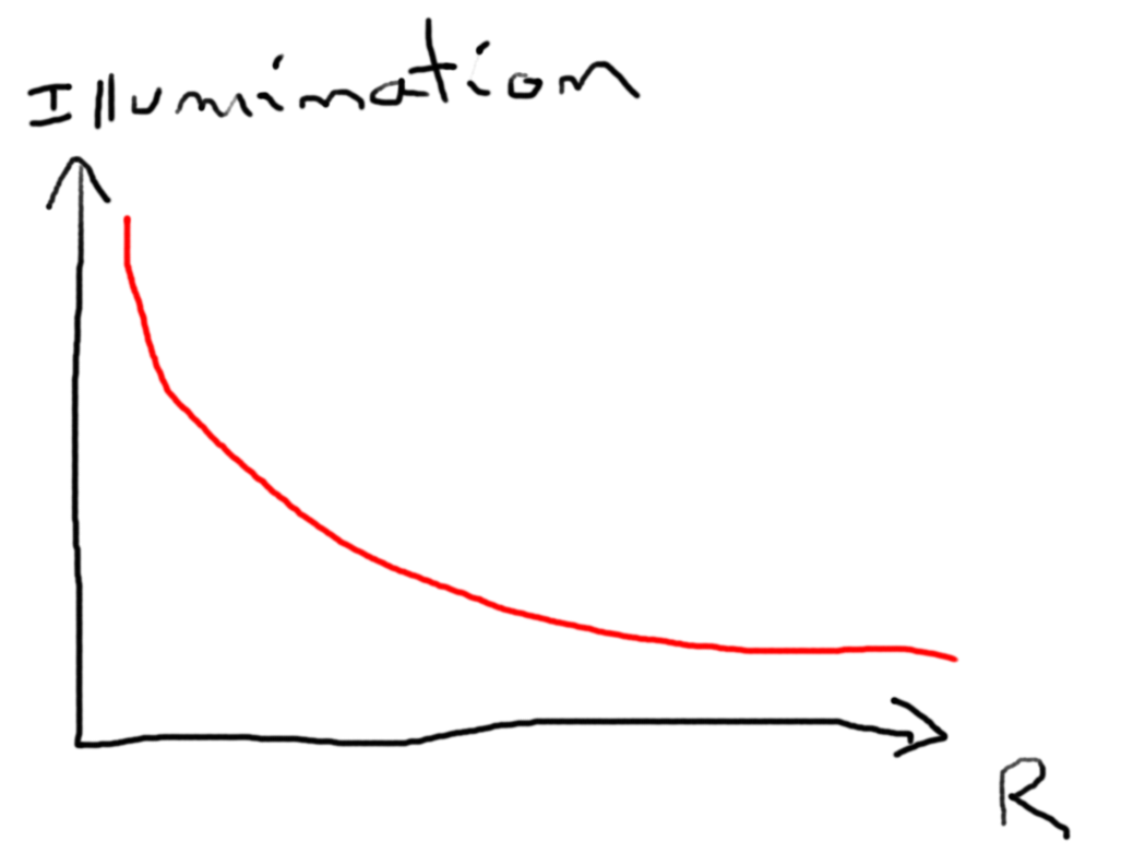
When the energy from the light increases, more free electrons and holes are created and therefore the resistance decreases further. In summary: The resistance of the LDR decreases with increasing incident light.
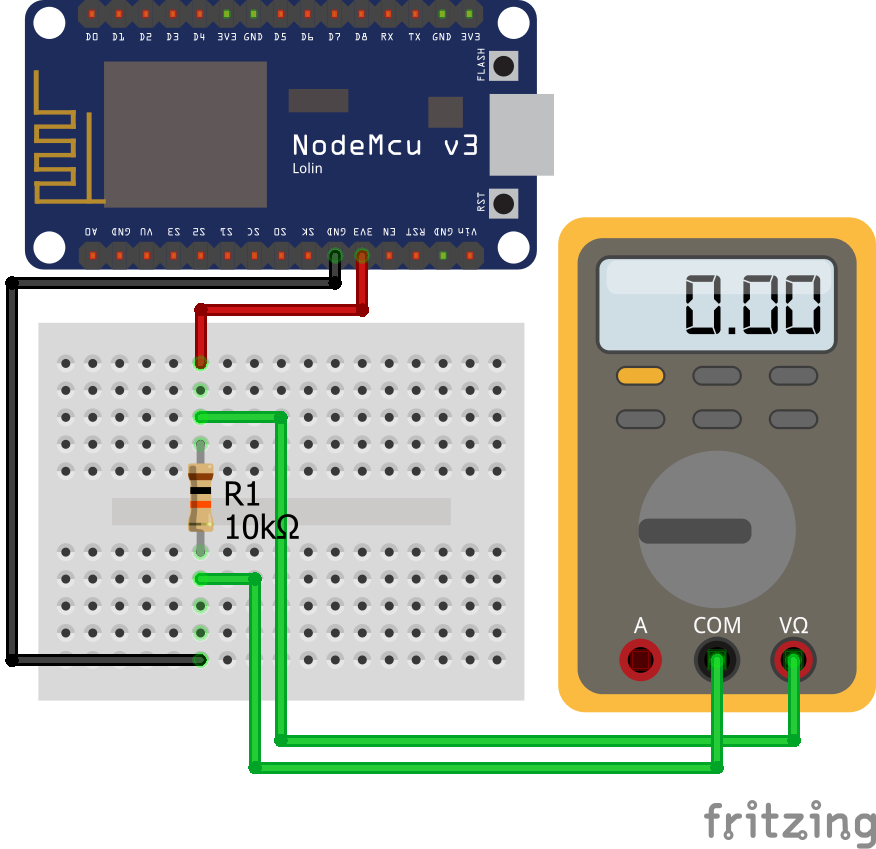
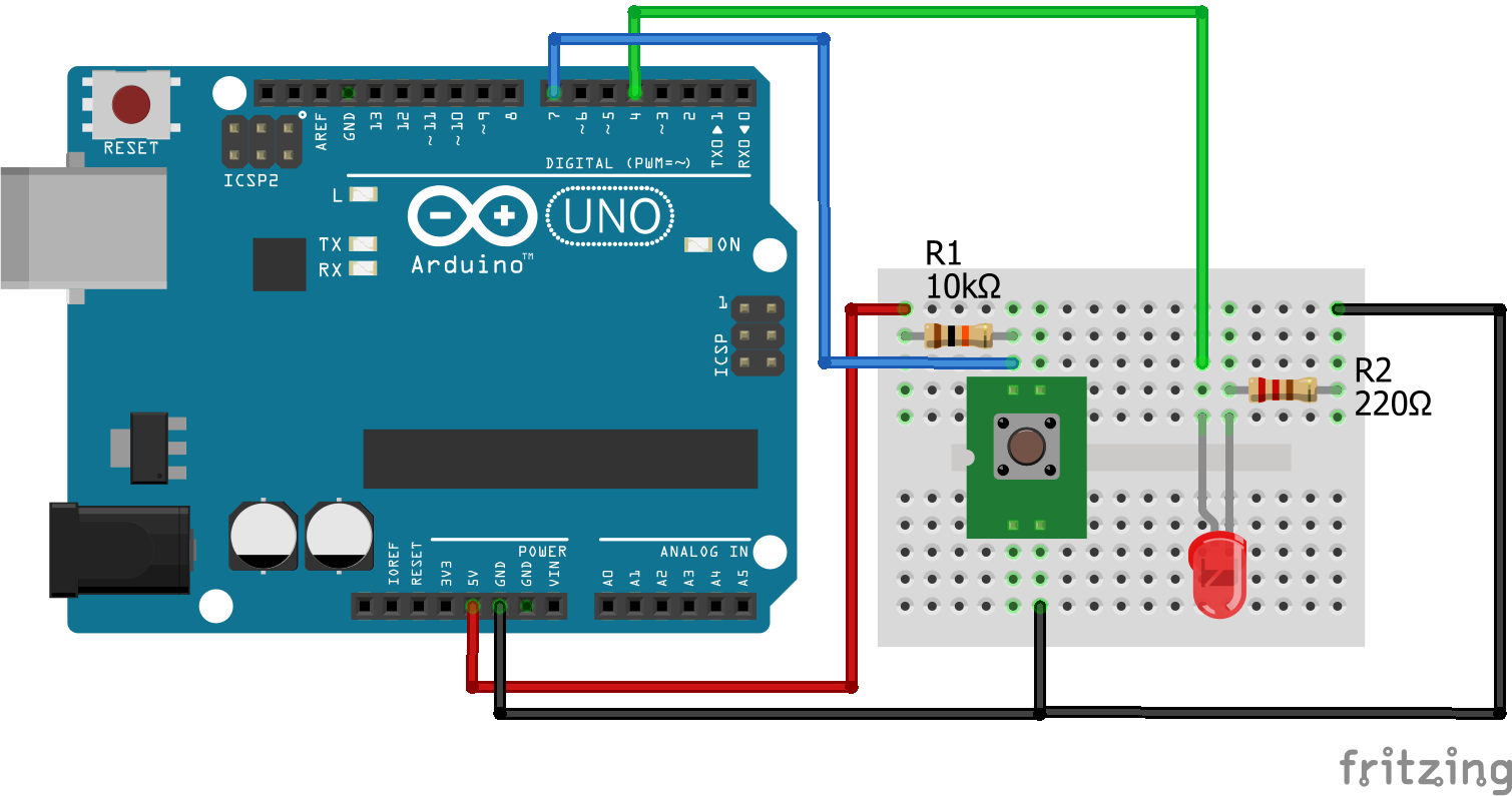
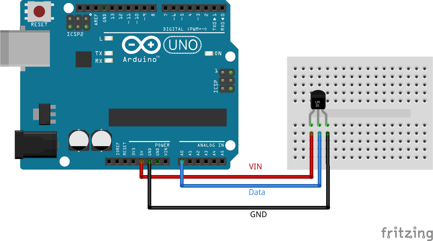
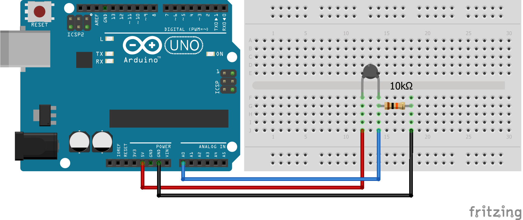
To measure the incident light a voltage divider with a 4.7kΩ resistor is used.
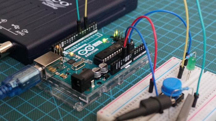
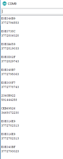
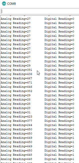
With the analog to digital converter (ADC) the Arduino converts the reference voltage of the voltage divider to a digital value. In the following example we want to read the incident light from a light sensor and print the analog and digital values.
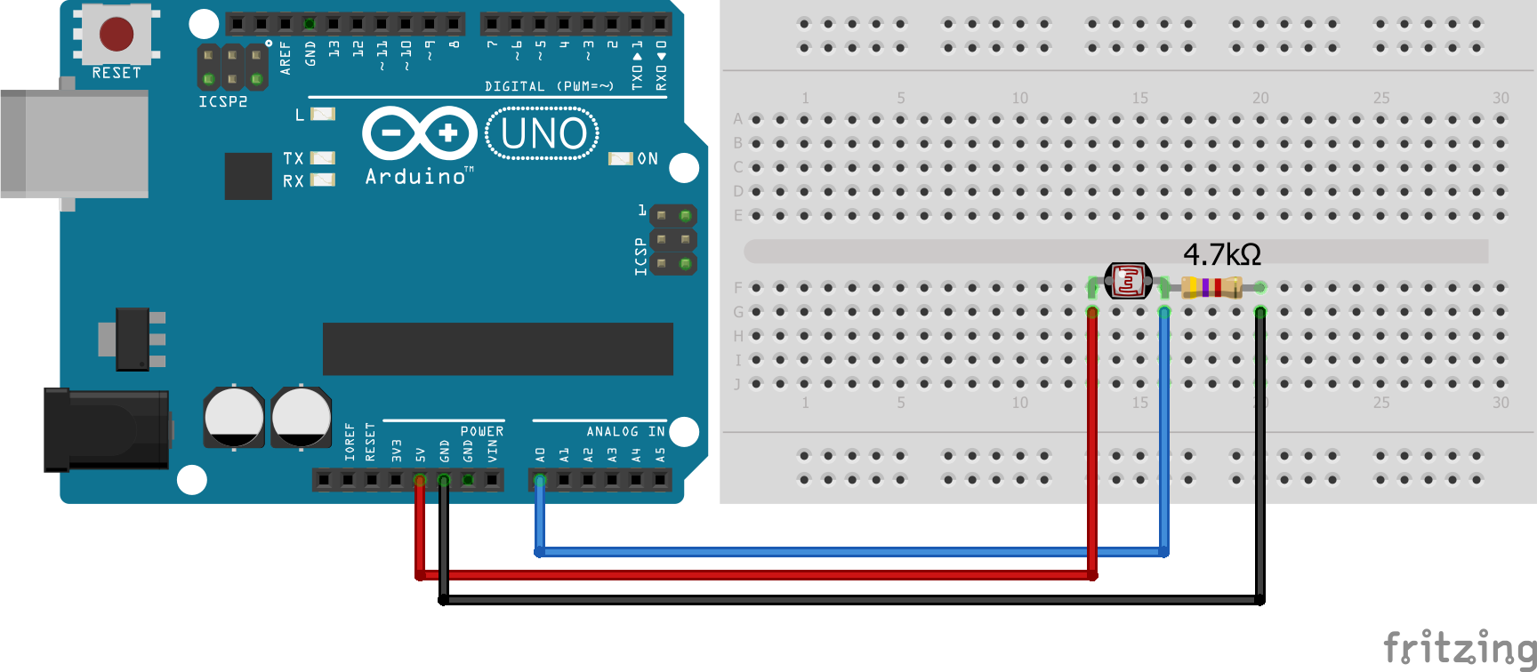
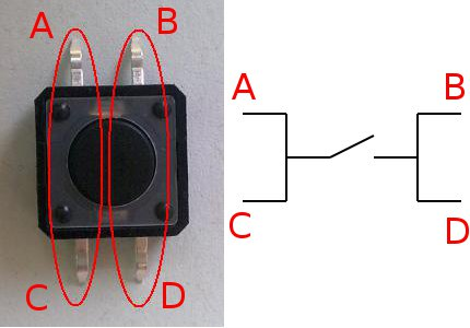
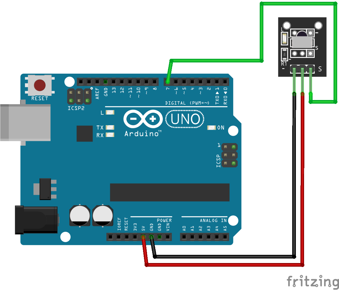
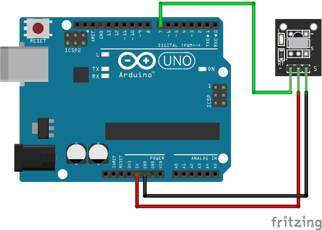
You see that the light sensor is nothing else than a resistor. Therefore you don’t have to worry about the connection sites. There is no false way to connect the light sensor.
#define Photoresistor A0
int reading;
int bright;

void setup() {
  Serial.begin(9600);  // set baud rate to 9600
}

void loop() {
  reading = analogRead(Photoresistor);
  bright = map(reading, 0, 1000, 0, 100);
  Serial.println(bright);
  delay(10);
}
Potentiometer
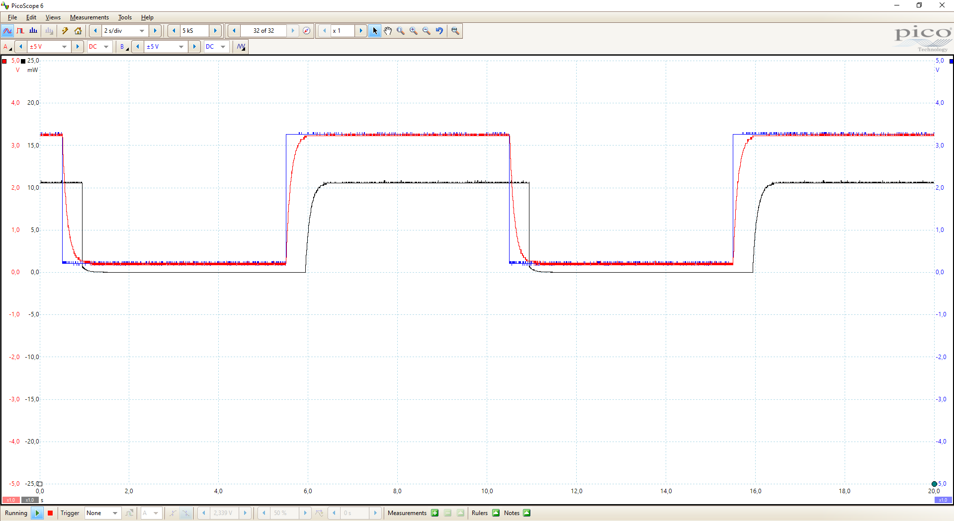
A potentiometer is an adjustable voltage divider and has therefore 3 connection pins. A potentiometer consists of an electrically non-conductive support on which a resistance material is applied, two terminals at the two ends of the resistive element and a movable sliding contact (also referred to as a grinder), which can divide the electrically fixed total resistance mechanically into two partial resistances corresponding to this total resistance.
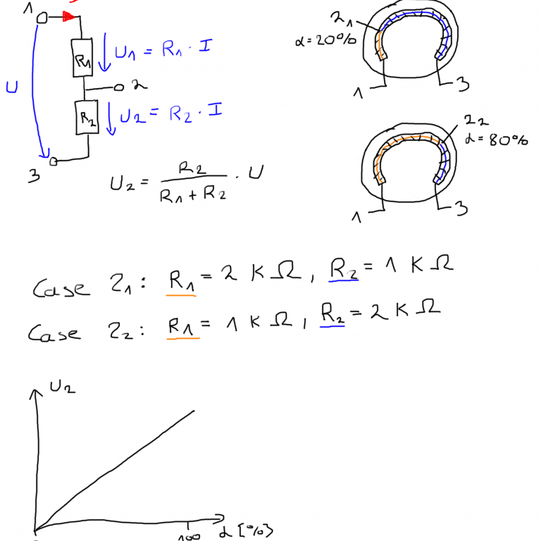
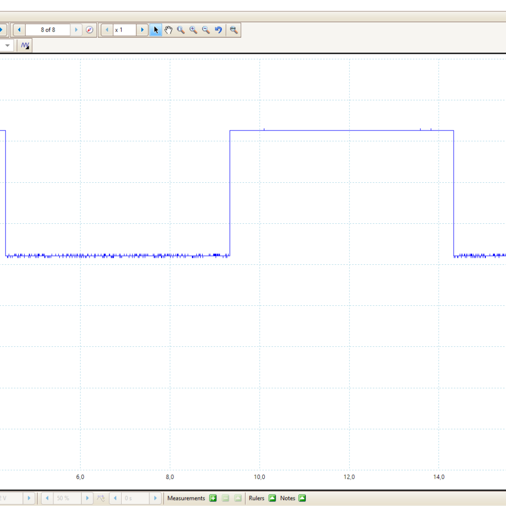
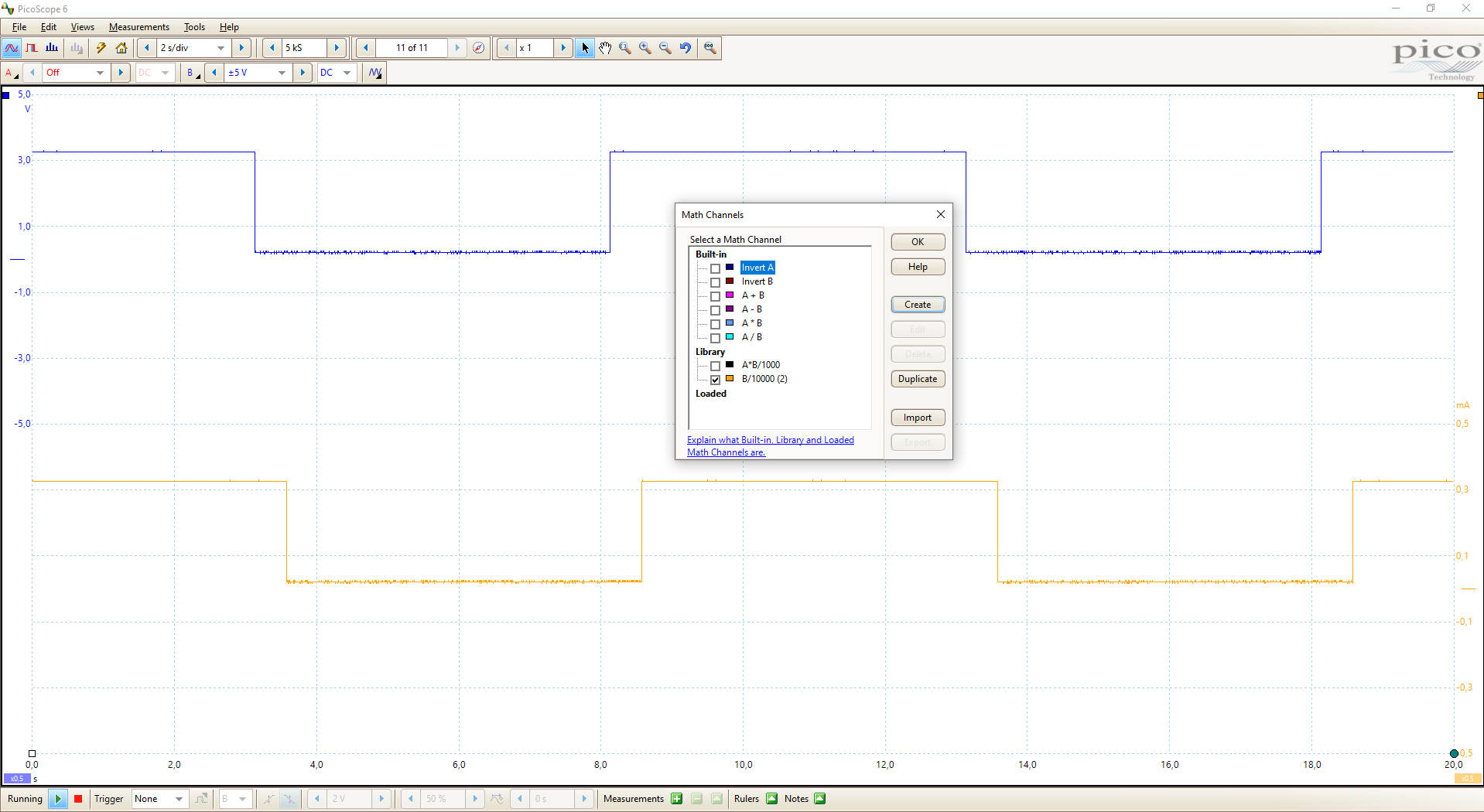
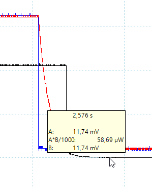
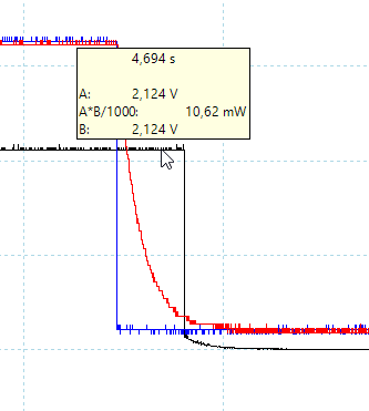
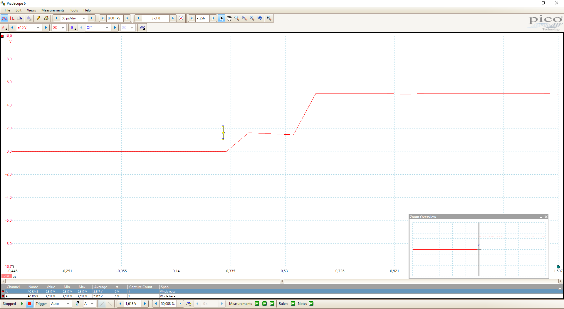
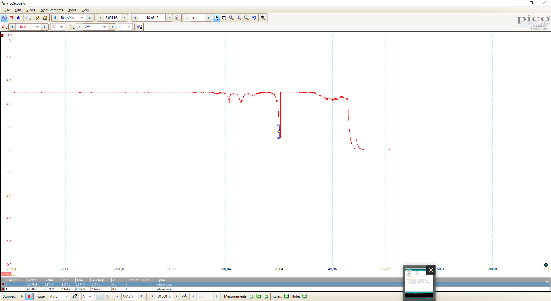
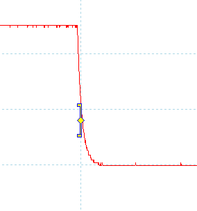
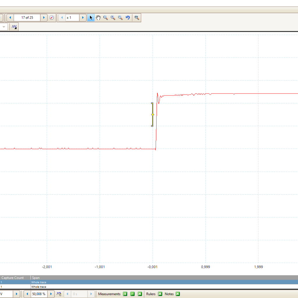
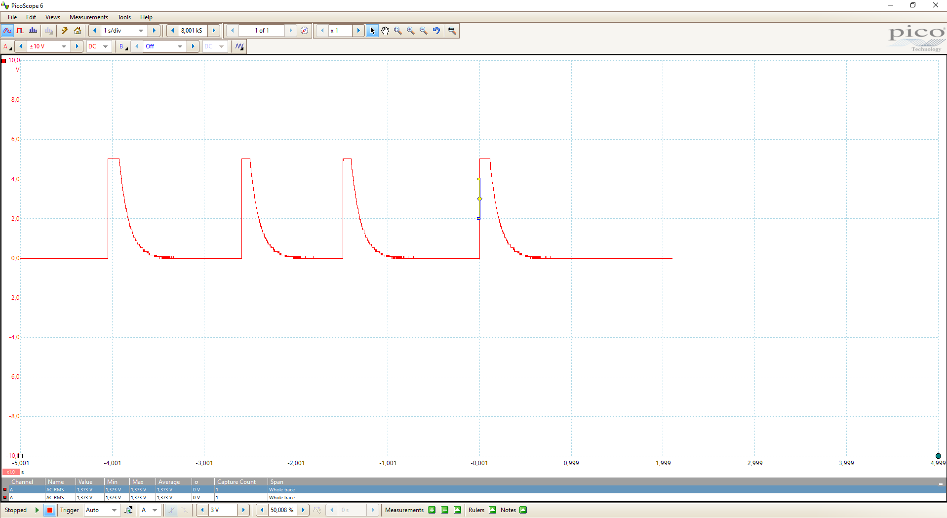
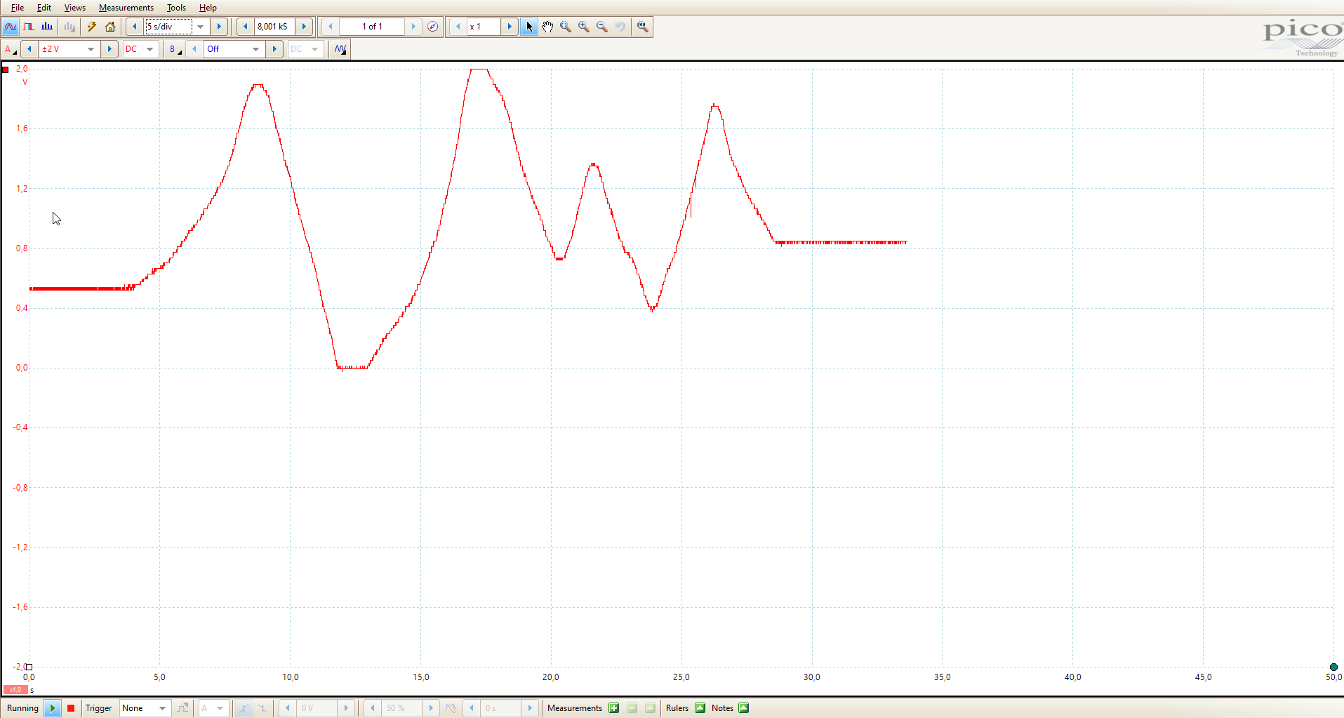
The picture below shows how the output voltage of the voltage divider is calculated. Depending on the position of the sliding contact, the output voltage U2 is changing. I measured the output voltage in an example with my oscilloscope using R1=5kΩ and R2=10kΩ. The picture of the oscilloscope shows clearly how I changed the position of the grinder.
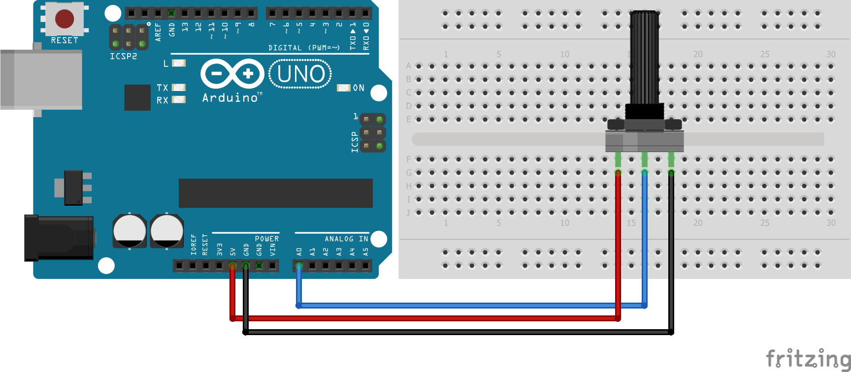
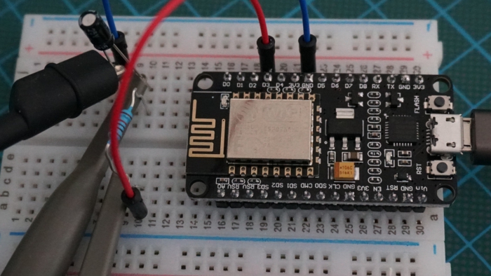
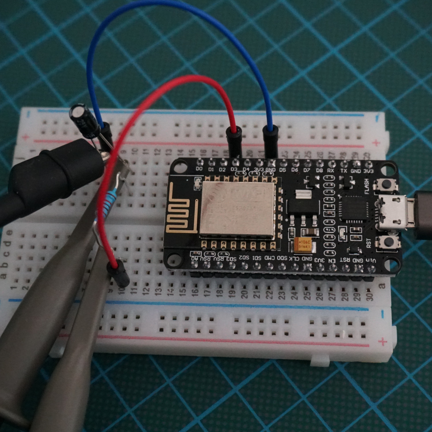
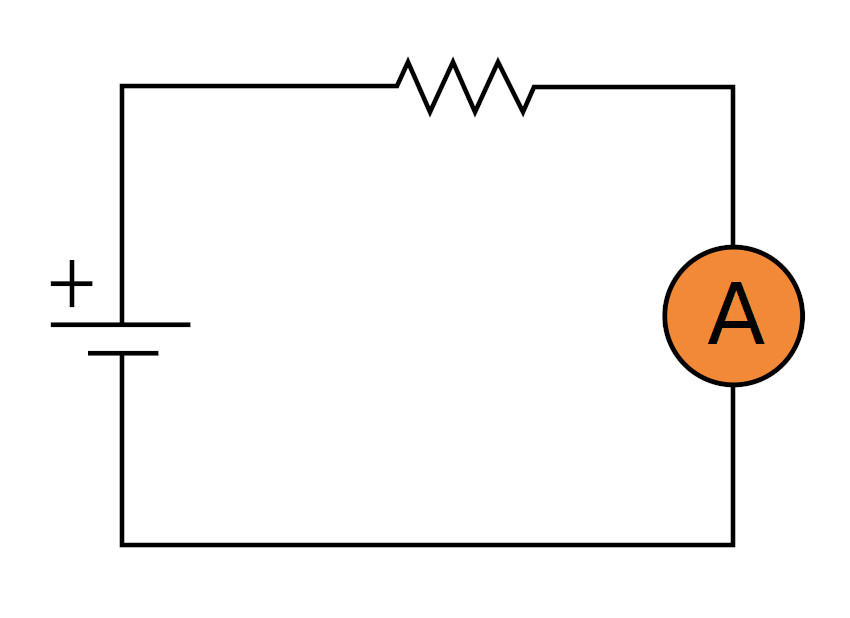
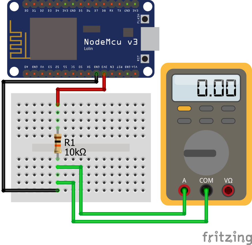
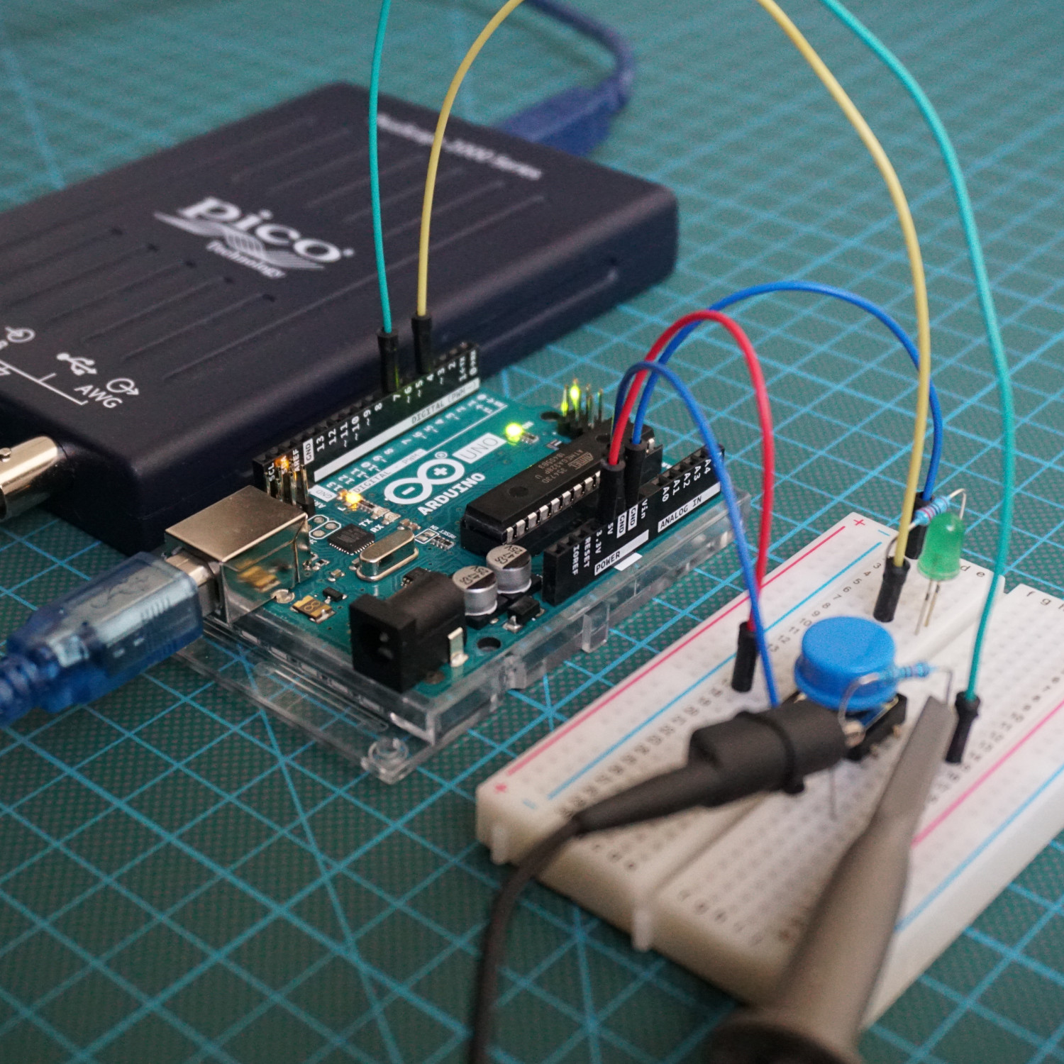
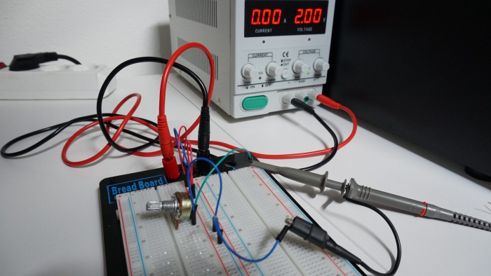
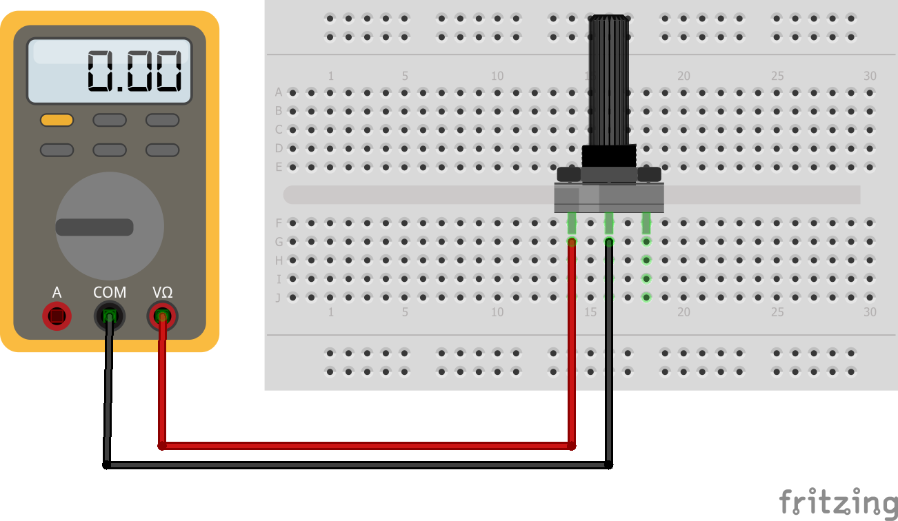
If instead of three pins only two pins are used the potentiometer acts as a variable resistor. In the following picture you see the connection between the potentiomenter and the multimeter. The following video shows the resistances measured by the multimeter in different positions of the sliding contact.
Thermistor
A thermistor is a resistor which changes the resistance based on the temperature. Thermistors are classified in two groups based on the behavior due to temperature changes:
- Negative Temperature Coefficient (NTC) thermistors: The resistance decreases with an increase in temperature.
- Positive Temperature Coefficient (PTC) thermistors: The resistance increases with an increase in temperature.
NTC thermistors are the most common and used in this article.
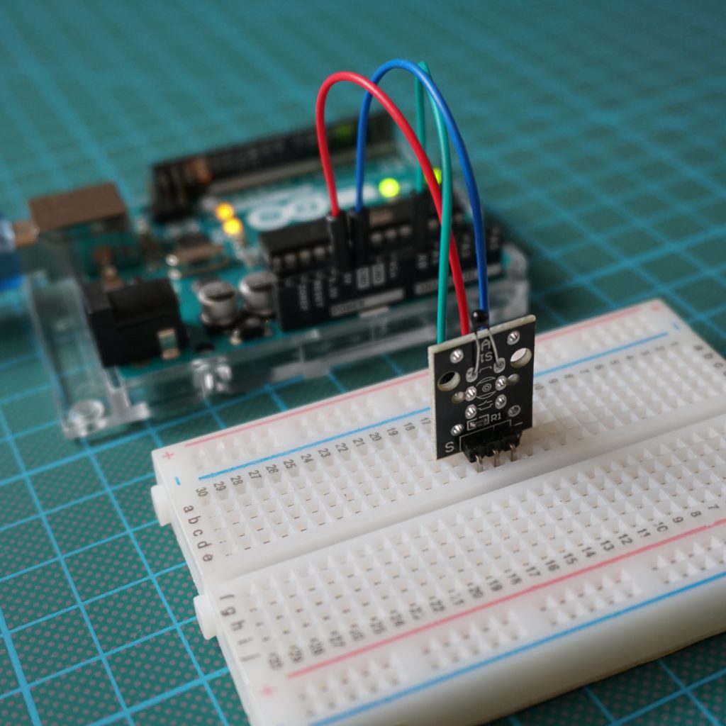
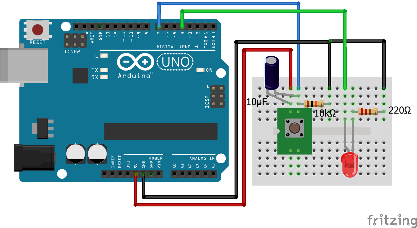
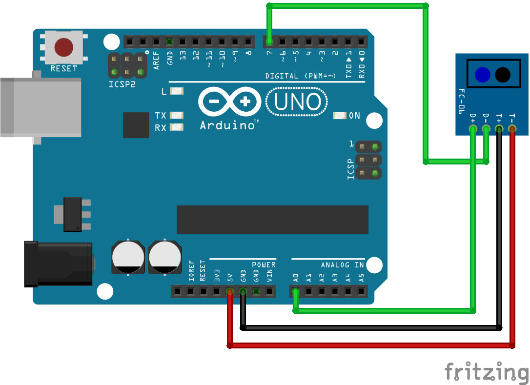
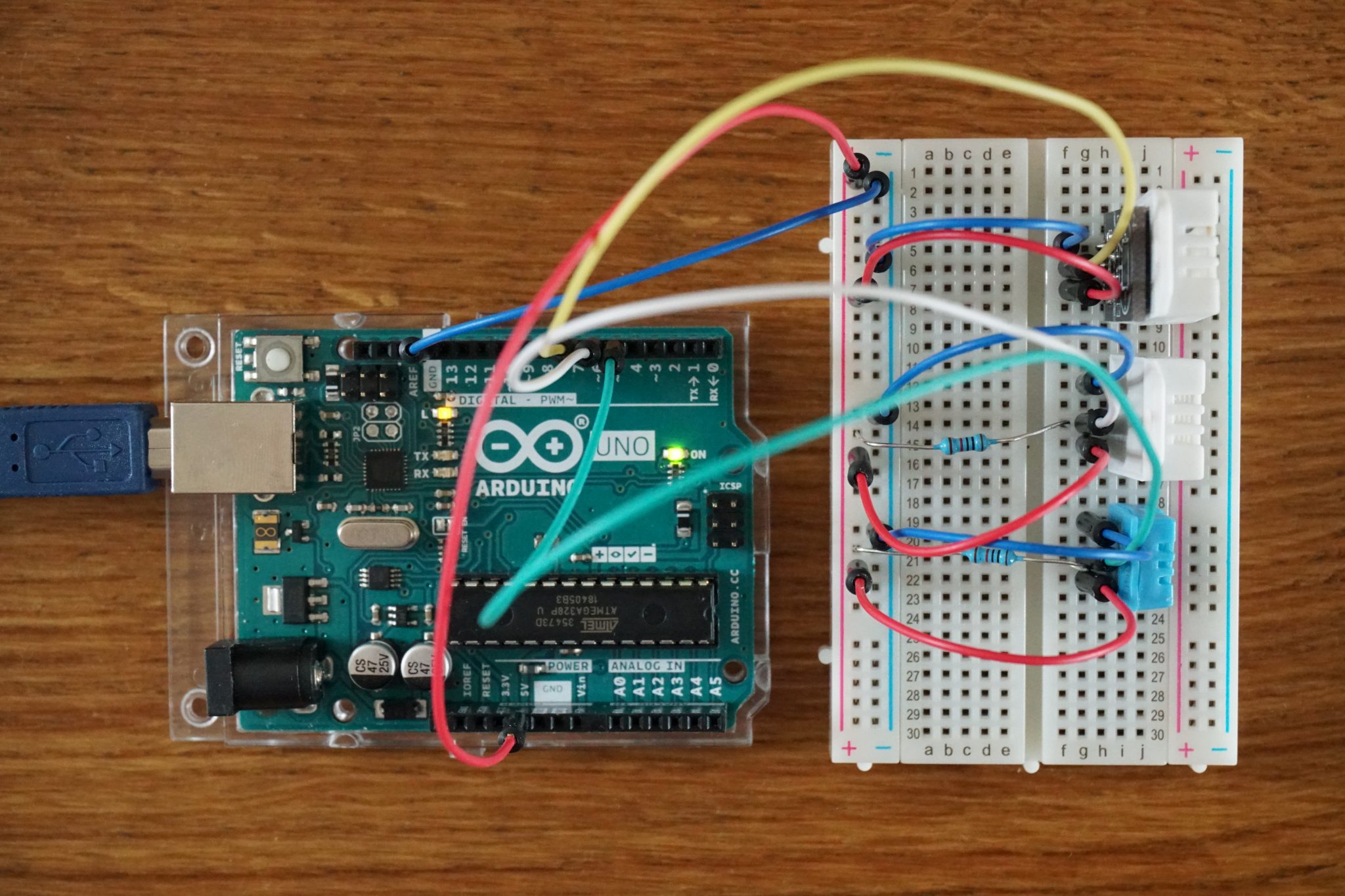
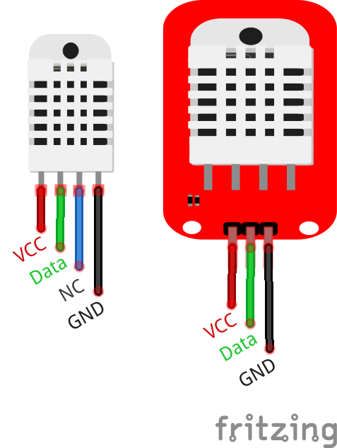
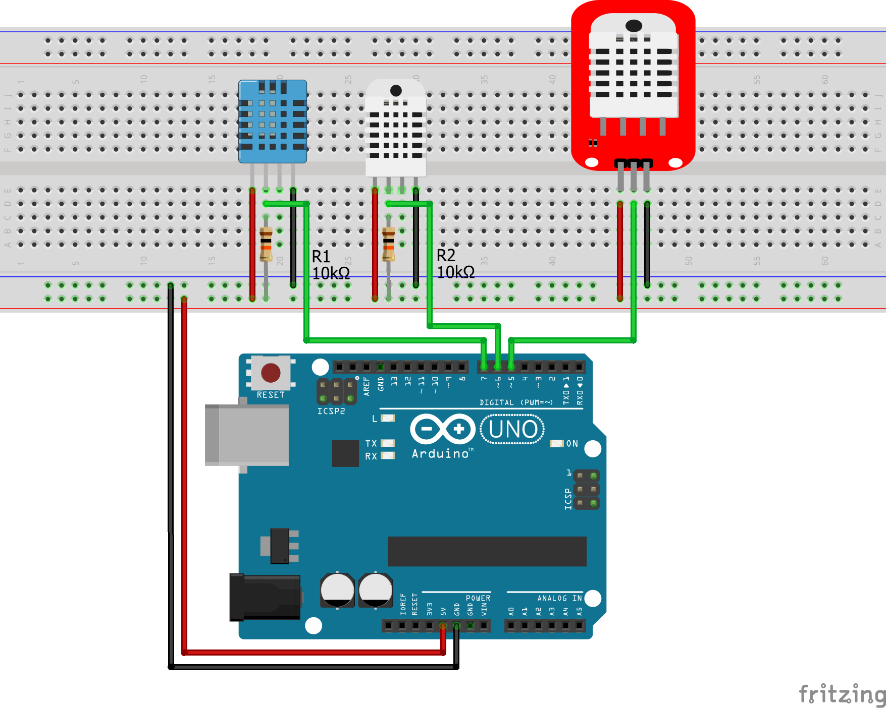
On the picture you see I use a thernistor module, which has the resistor in series already included. In my case the resistor is 10kΩ, which I measured with my multimeter. Therefore the separate resistor is missing in the picture. The circuit is already again a voltage divider which allows us to measure the voltage drop on the thermistor. Because the resistor is directly connected to ground we have a pull-up resistor. This is important for the calculation of the resistance of the thermistor. If you do not know the difference between a pull-down and pull-up resistor, you find here an article explaining the differences in detail.
Also It is possible to calculate the temperature based on the measurements of the thermistor voltage divider. Therefor we use the Steinhart equation. The following sketch shows you how to measure the voltage and the temperature with a thermistor.
int ThermistorPin = A0;
int Vo;
float R1 = 10000; // value of R1 on board
float logR2, R2, T;

//steinhart-hart coeficients for thermistor
float c1 = 0.001129148, c2 = 0.000234125, c3 = 0.0000000876741;

void setup() {
  Serial.begin(9600);
}

void loop() {
  Vo = analogRead(ThermistorPin);
  R2 = R1 * (1023.0 / (float)Vo - 1.0); //calculate resistance on thermistor
  logR2 = log(R2);
  T = (1.0 / (c1 + c2*logR2 + c3*logR2*logR2*logR2)); // temperature in Kelvin
  T = T - 273.15; //convert Kelvin to Celcius
 // T = (T * 9.0)/ 5.0 + 32.0; //convert Celcius to Farenheit

  Serial.print("Temperature: ");
  Serial.print(T);
  Serial.println(" C");

  delay(500);
}
Conclusion
Do you have any further questions about resistors, the voltage divider, photoresistors, rotary encoder or thermistors? Use the comment section below to ask your questions.