Oscilloscope voltage, current, power measurements

In this tutorial you learn how to measure different electrical metrics:

  • Voltage across a resistor
  • Current through with Ohms Law
  • Power consumption of a capacitor

Before we dive deeper into the measurements let’s start with basic information about oscilloscopes to get a better foundation.

Oscilloscope Thumbnail

Table of Contents

General Information about Oscilloscopes

An oscilloscope is a typical laboratory instrument. The purpose of this instrument is to display and analyze waveform of electronic signals with frequencies from 1 hertz (Hz) up to several megahertz (MHz). Typically you use the oscilloscope to measure the voltage as a function of time. The oscilloscope display the voltage not as a plain number like a multimeter, but rather over time from the left to the right side. Like a multimeter also an oscilloscope is able to process and display alternating current (AC) or pulsating direct current (DC). The horizontal sweep is measured in time per seconds and the vertical deflection is measured in volts per division.

I personally use an USB oscilloscope from Pico Technology the Picoscope 2204 A. Because it is an USB oscilloscope it does not have any display. I can directly connect the oscilloscope with my computer and there is a software that gives me the interface of a standard oscilloscope. The main advantage of an USB oscilloscope is that there are cheap devices on the market because there is no need for a display or buttons. That is saving a lot of costs in comparison to non USB oscilloscopes.

The following table give you an overview about my Picoscope 2204 A.

CriteriaSpecification
Bandwidth10 MHz
Number of channels2
Input ranges+- 50 mV to +- 20 V
Input sensitivity10 mV/div to 4V/div
Minimum detectable pulse width5 ns
Maximum sampling rate100 MS/s
Shortest timebase10 ns/div
Maximum waveforms per second2000
Advanced triggersEdge, window, pulse width, window pulse width, dropout, window dropout, interval, logic
Trigger typesRising or falling edge
Standard output signals of function generatorSine, square, triangle, DC voltage, ramp, sinc, Gaussian, half-sine
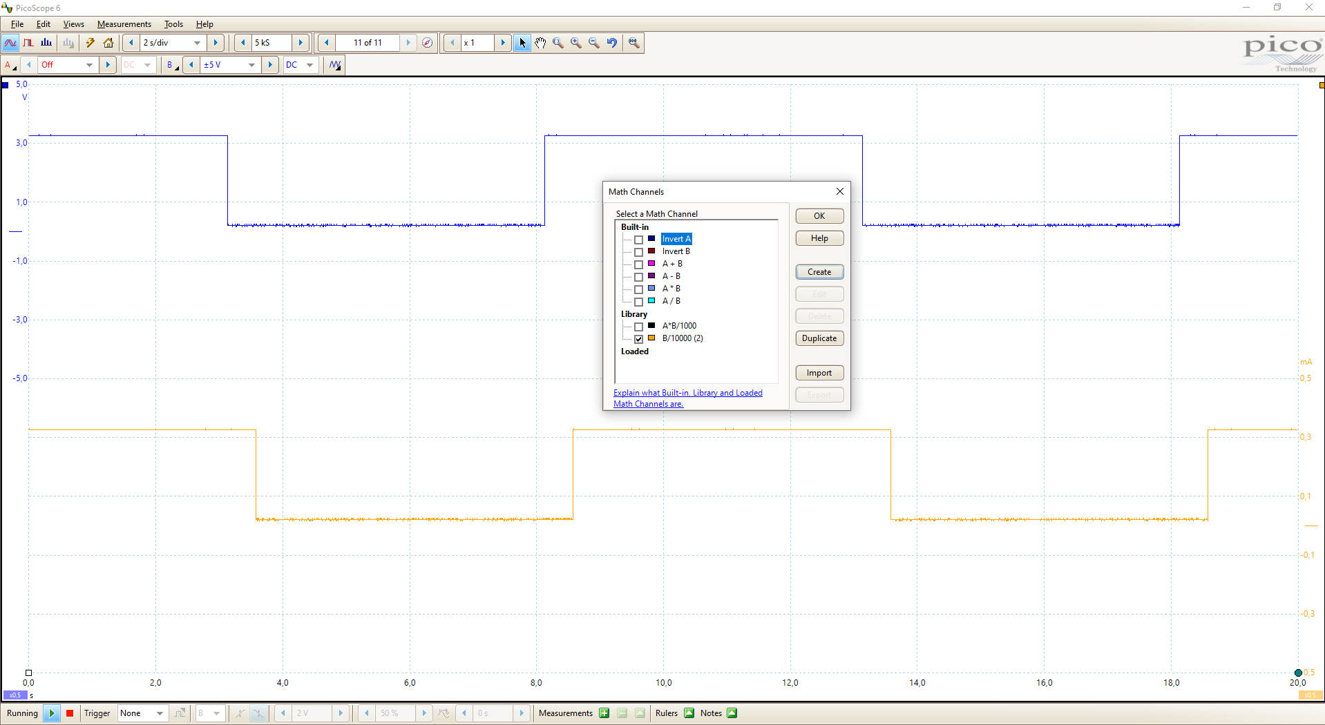
Math channels and Software filters−x, x+y, x−y, x*y, x/y, x^y, sqrt, exp, ln, log, abs, norm, sign, sin, cos, tan, arcsin, arccos, arctan, sinh, cosh, tanh, freq, derivative, integral, min, max, average, peak, delay, duty Highpass, lowpass, bandpass, bandstop

The following table gives you an overview of all components and parts that I used for this tutorial. I get commissions for purchases made through links in this table.

ComponentAmazon LinkAliExpress Link
Arduino Nano AmazonAliExpress
Arduino Pro Mini AmazonAliExpress
Arduino Uno AmazonAliExpress
Arduino Mega AmazonAliExpress
ESP32 ESP-WROOM-32AmazonAliExpress
ESP8266 NodeMCU AmazonAliExpress
ESP8266 WeMos D1 Mini AmazonAliExpress
Capacitor Kit AmazonAliExpress
Resistor Kit AmazonAliExpress
USB Oscilloscope AmazonAliExpress

Microcontroller Voltage Measurement with an Oscilloscope

To measure a voltage with an oscilloscope is the easiest part in working with this device. You only have to connect one probe with both ends before and after the electrical component you want to measure the voltage. The picture on the right shows you that the oscilloscope is therefore in parallel to the electrical component.

In my example I want to measure the voltage across a 10kΩ resistor. As a power source I use the NodeMCU V2 because I want to power on and power off the circuit for a given time. The following sketch shows the circuit and the sketch I used.

void setup() {
  pinMode(D3, OUTPUT);  // LED pin as output
}

void loop() {
  digitalWrite(D3, HIGH);
  delay(5000);
  digitalWrite(D3, LOW);
  delay(5000);
}
Measure Voltage Steckplatine

Then next pictures shows the output of the oscilloscope. On the x-aches you see that the circuit is powered on for 5 seconds and than powered off of another 5 seconds and so on. What is really interesting this, that even if I set the output pin to low, there is still a little voltage of around 0.2V on the resistance which has a lot of ripple. If the output is set to HIGH the output voltage of the GPIO is 3.3V which is shown in the picture.

Oscilloscope Voltage Measurement

Microcontroller Datasheet eBook

The 35 pages Microcontroller Datasheet Playbook contains the most useful information of 14 Arduino, ESP8266 and ESP32 microcontroller boards.

Microcontroller Current Measurement with an Oscilloscope

It is possible to measure the current in a circuit directly with a current probe. But these are very expensive and I do not have one. An other possibility to measure the current is to use a known resistor and Ohms law: U=R*I

Therefore if we can measure the voltage over a known resistor, we also know the current in the circuit. We use the same setup and the same sketch of the voltage measurement with an oscilloscope. The only thing we add is a math channel in the oscilloscope. With a math channel I can add virtual channels based on mathematical operations of the real input channels. The following picture shows that I added the mathematical channel: U/10000 because I used a 10 kΩ resistor.

Circuit Current Measurement
Measure Current Steckplatine
Oscilloscope Current Measurement

The time on the x-axis is not the same for the mathematical channel, because the values for the mathematical channel are calculated with the real values one period before.

Within the software of the oscilloscope I can measure the min and max current. The minimal current is 22 μA and the maximal current is 323 μA. Also I proved the min and max value from the oscilloscope against a measurement done with a standard multimeter.

Multimeter Min Current Validation
Multimeter Max Current Validation

Microcontroller Power Measurement with an Oscilloscope

Now we want to measure the power consumption of a capacitor. How can we do this? No problem, because we will combine what we learned so fare. The power is calculated by: P=U*I

  1. We measure the voltage over the capacitor directly with the first channel of the oscilloscope.
  2. We can measure the current by connecting a resistor in series with the capacitor, measuring the voltage over the resistor and calculating the current in the circuit.

The following picture shows how the electrical parts are connected.

Measure Power Steckplatine

Now we want to measure the power. The power is calculated by P_C=U_C*I = U_C*U_R/R where

  • U_C is the voltage over the capacitor
  • U_R is the voltage over the resistor
  • R is the resistor and 10 kΩ

You see the power consumption in the following picture as black line.

Oscilloscope Power Measurement

The minimal power consumption of the capacitor is 58.69 μW and the maximal power consumption is 10.62 mW. Also here the note that the time on the x-axis is not the same for the mathematical channel.

Power Consumption Min
Power Consumption Max

Conclusion

Now you know how to measure the voltage, current and power with an oscilloscope. Do you have any questions about the measurements? Do you use an oscilloscope or are you planning to buy one? I am happy when you leave a comment below.

Leave a Comment