Reduce the ESP32 Power Consumption in 3 Simple Steps
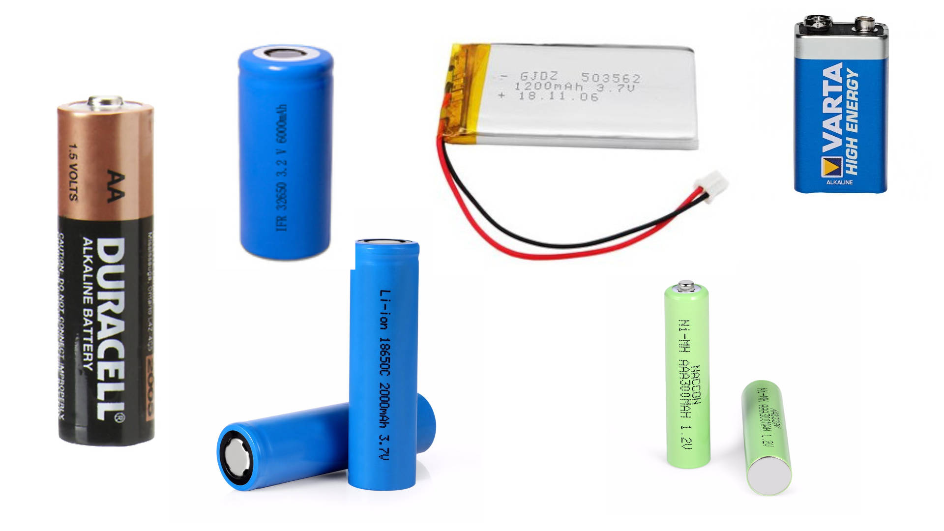
If you want to create a project that runs on battery, you have to make sure that the power consumption of your ESP32 board is as low as possible to increase the lifespan of the battery.
In this tutorial I show you how to reduce the power consumption for a whole ESP32 based board up to -99.98%.
The steps to reduce the power consumption are shown in the following table of content.

Table of Contents
If you are only interested in the results of the whole guide, the following table shows the final measurements for 6 different ESP32 based boards.
I get commissions for purchases made through links in the following table.
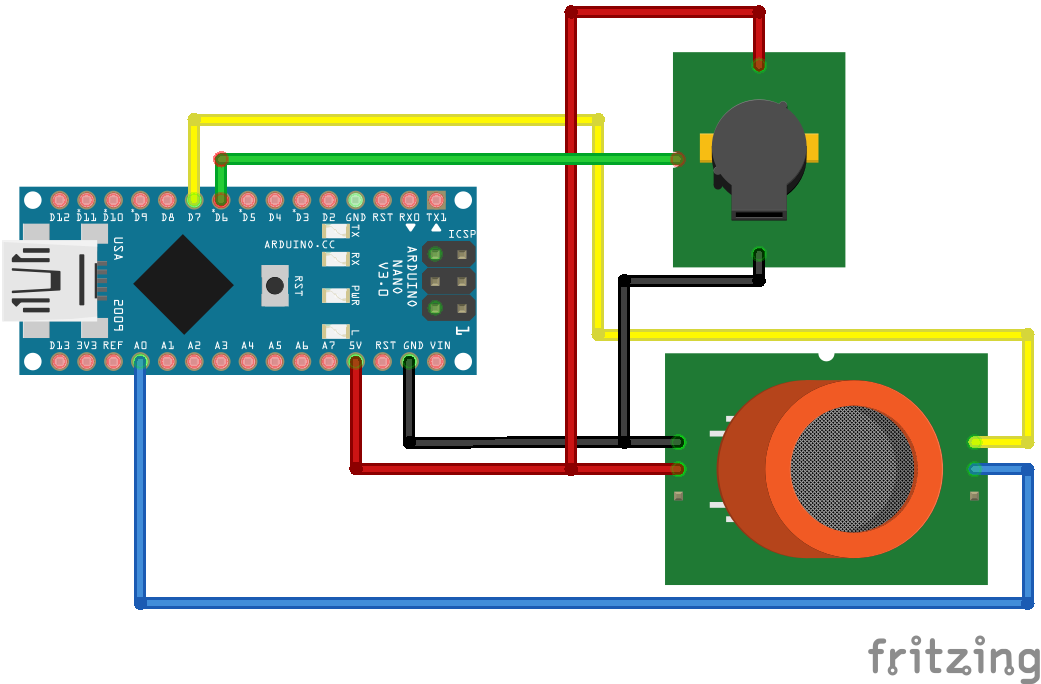
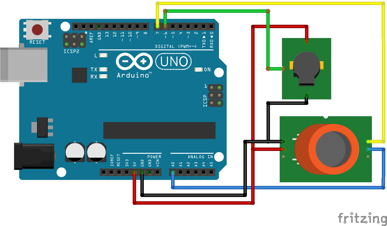
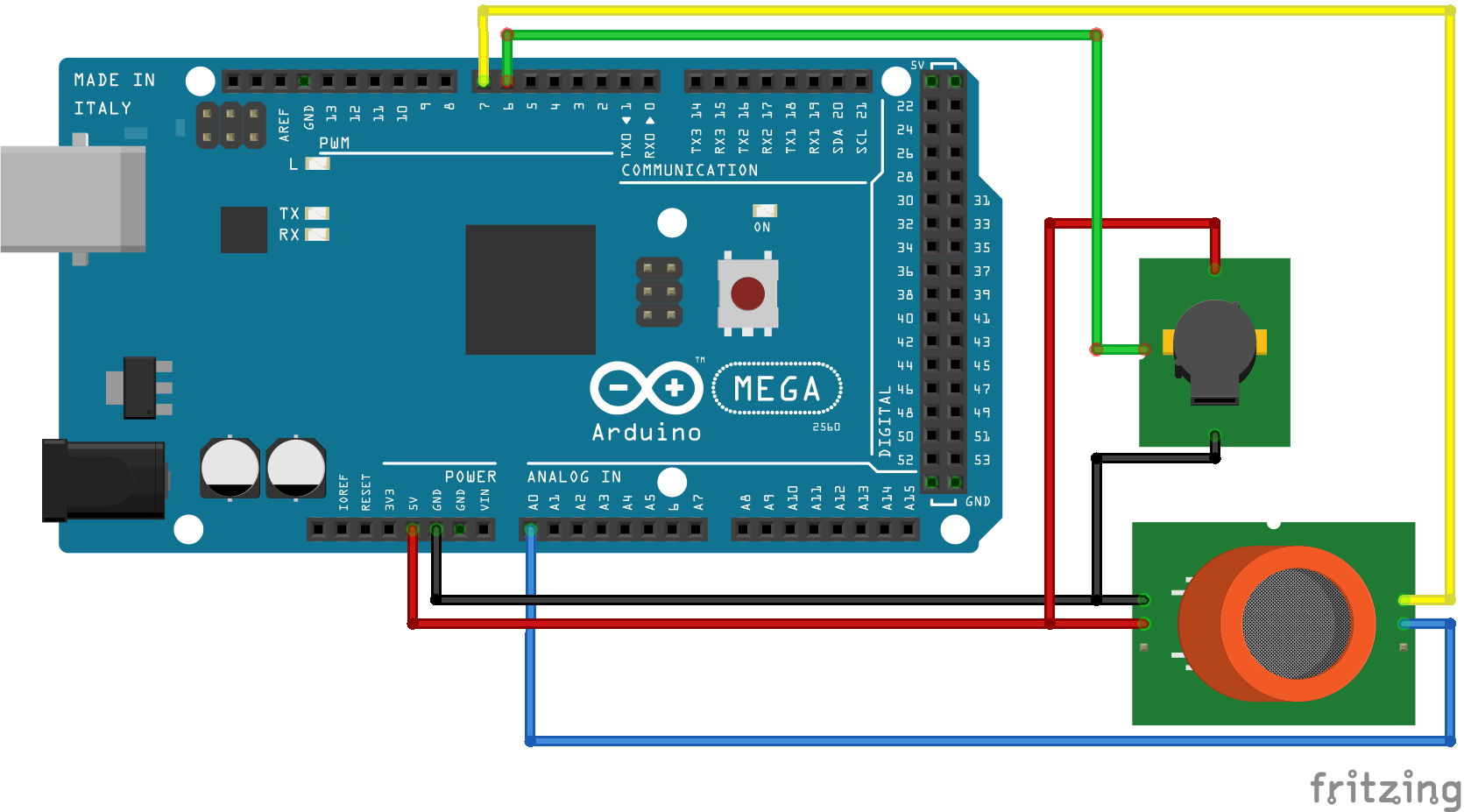
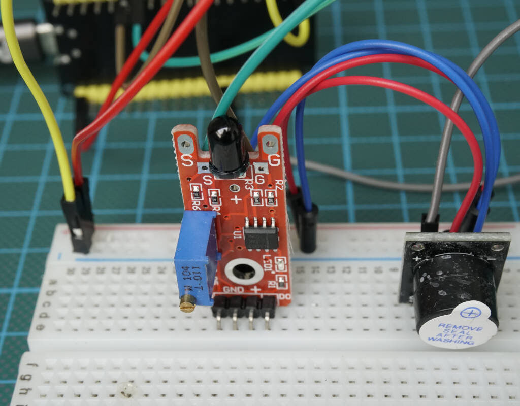
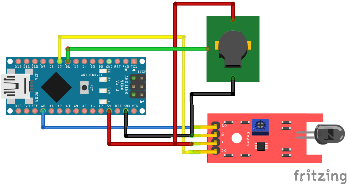
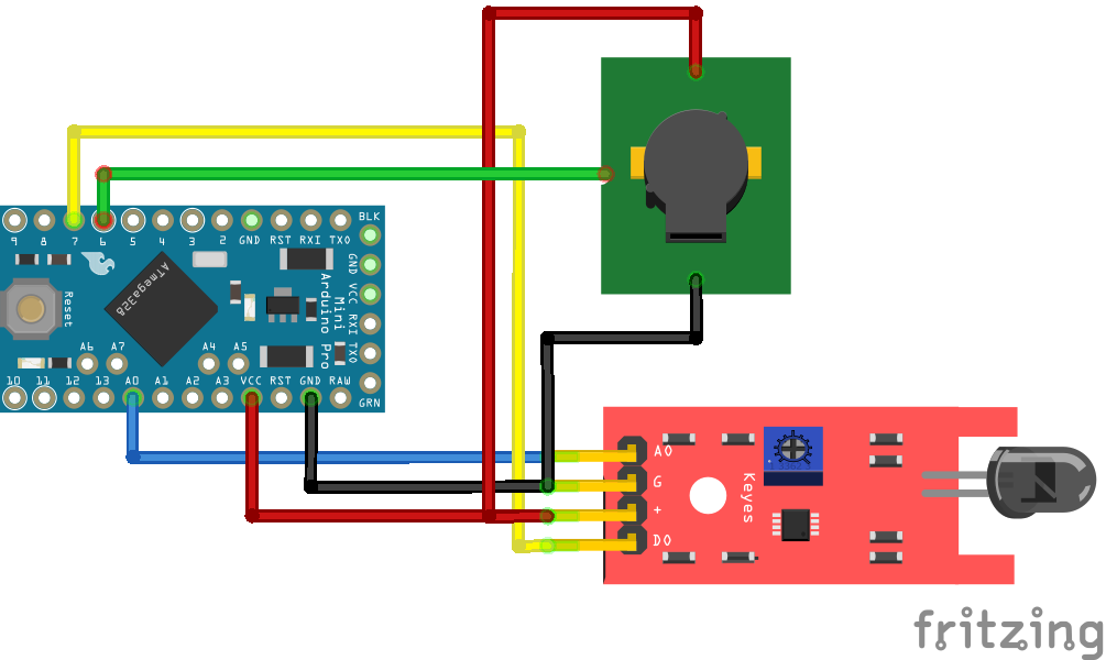
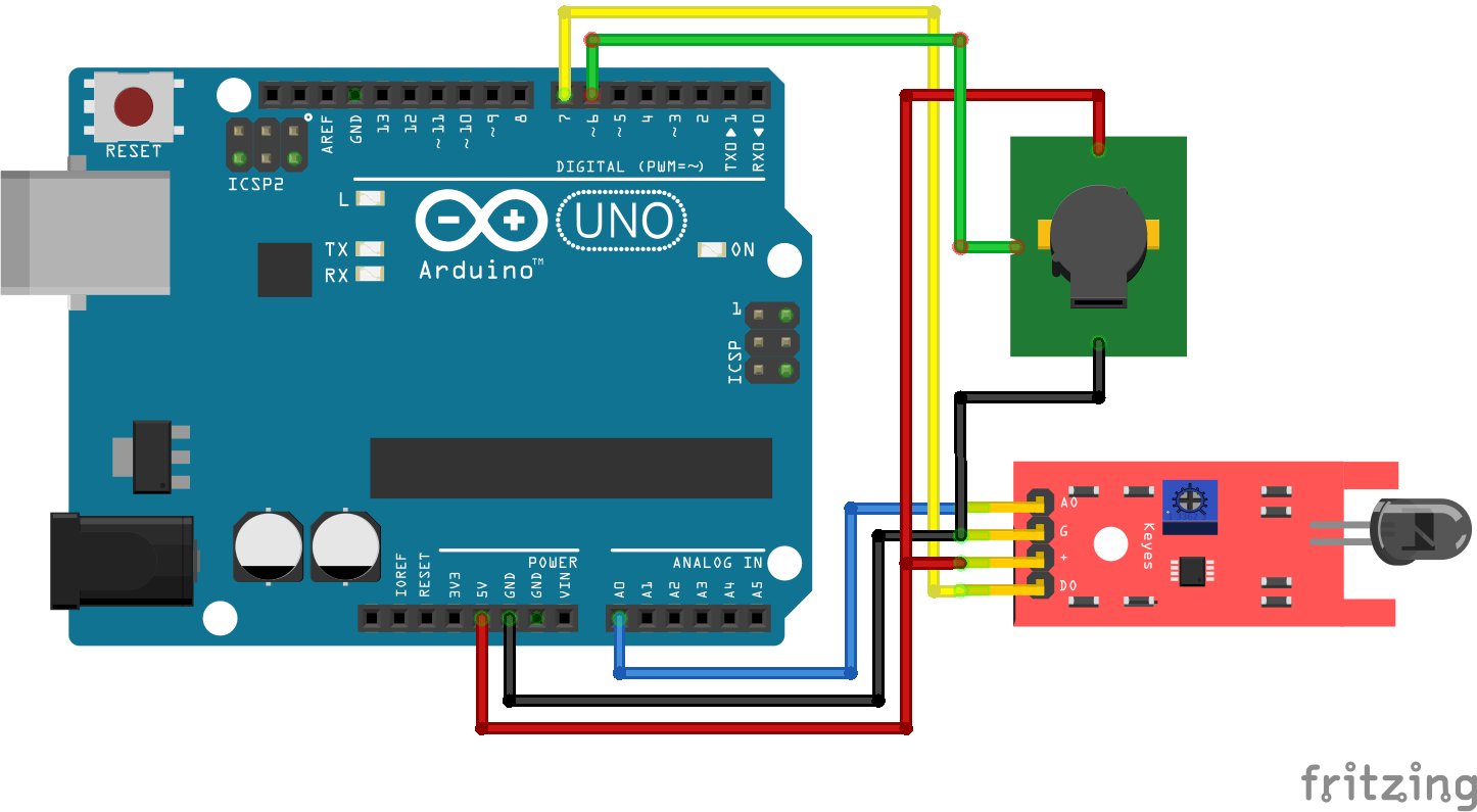
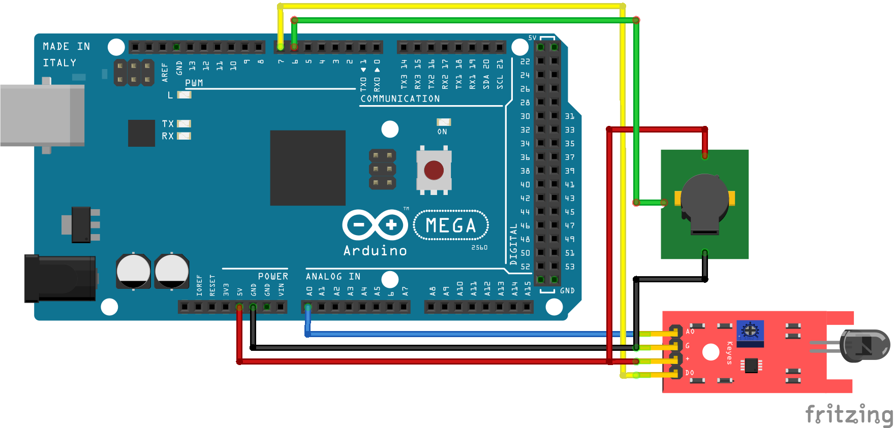
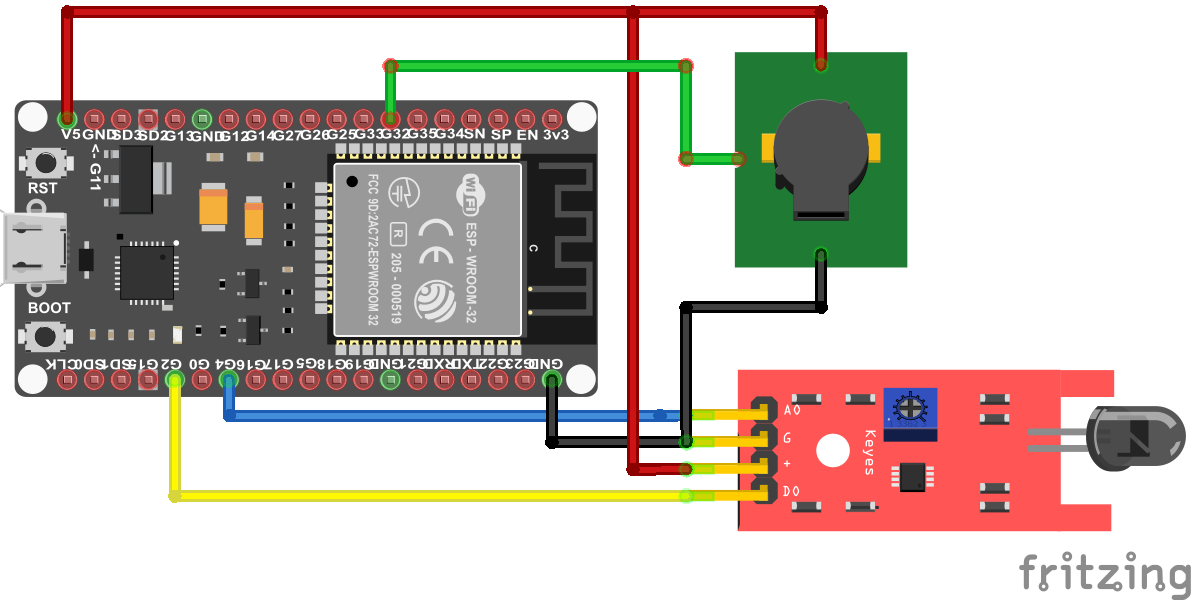
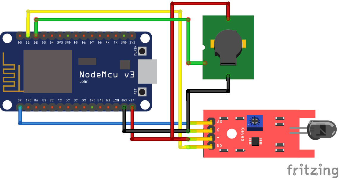
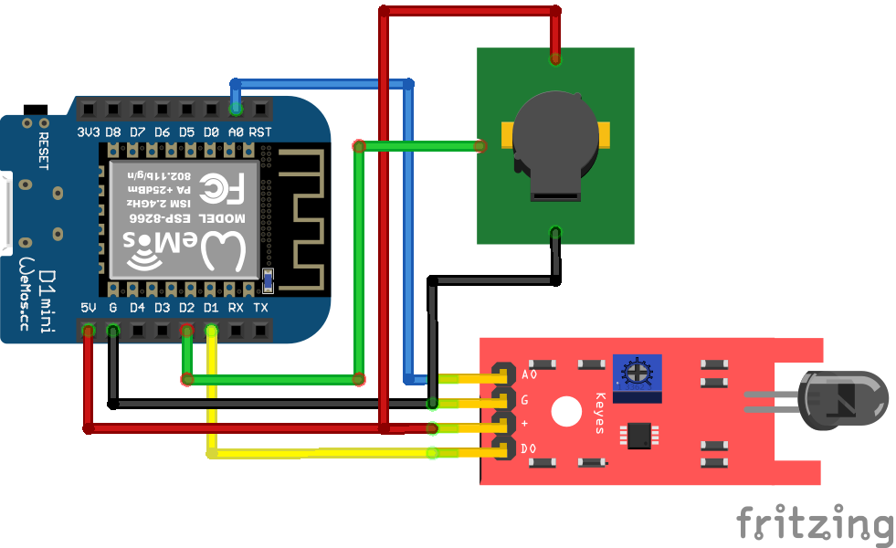
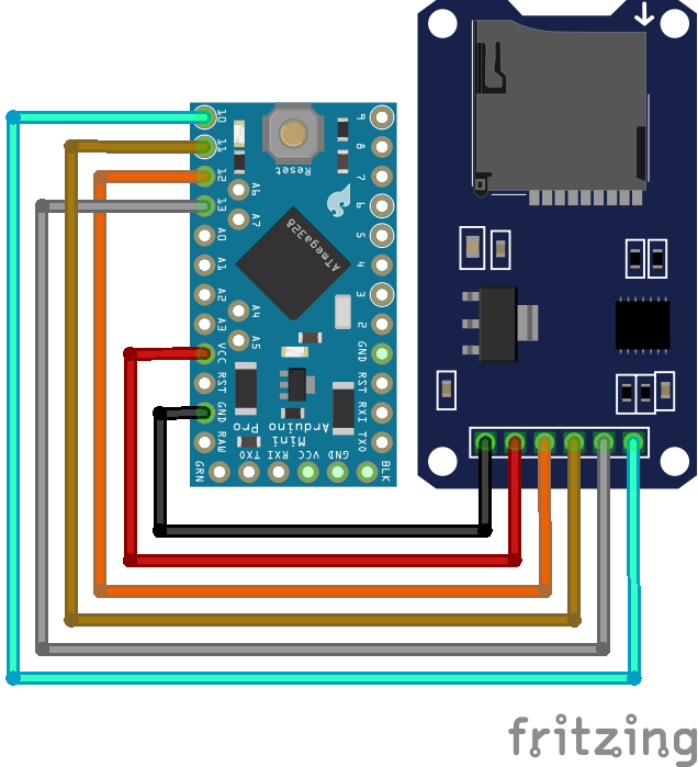
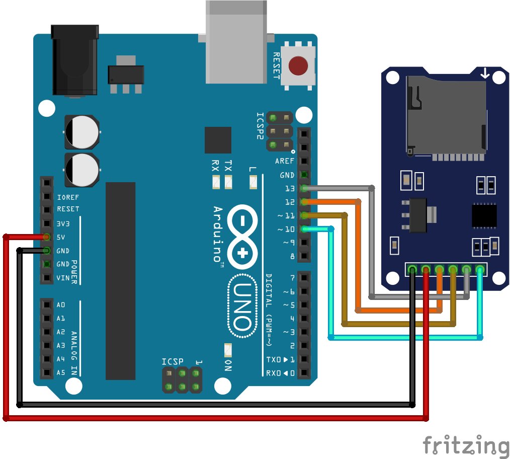
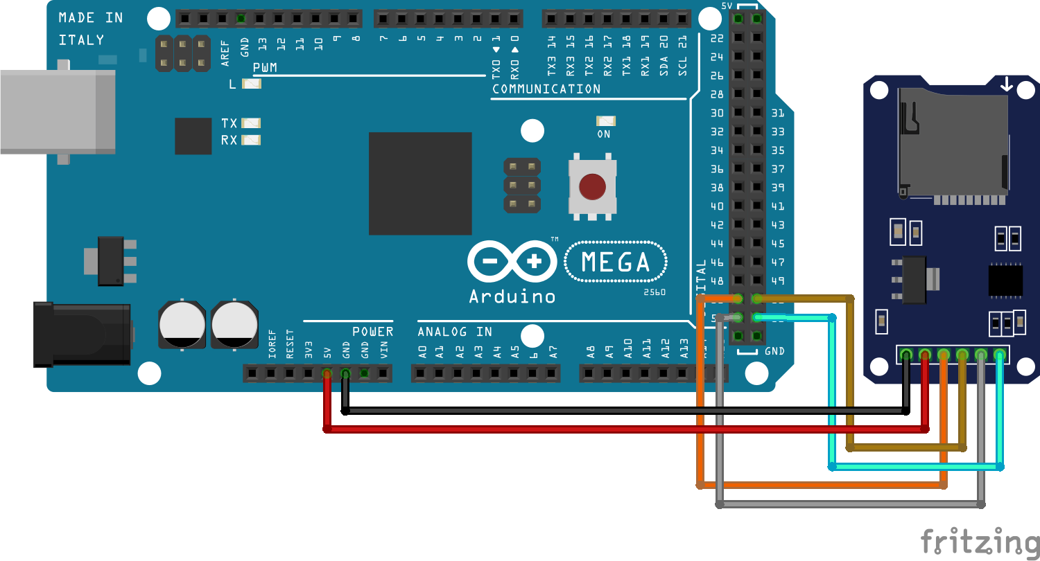
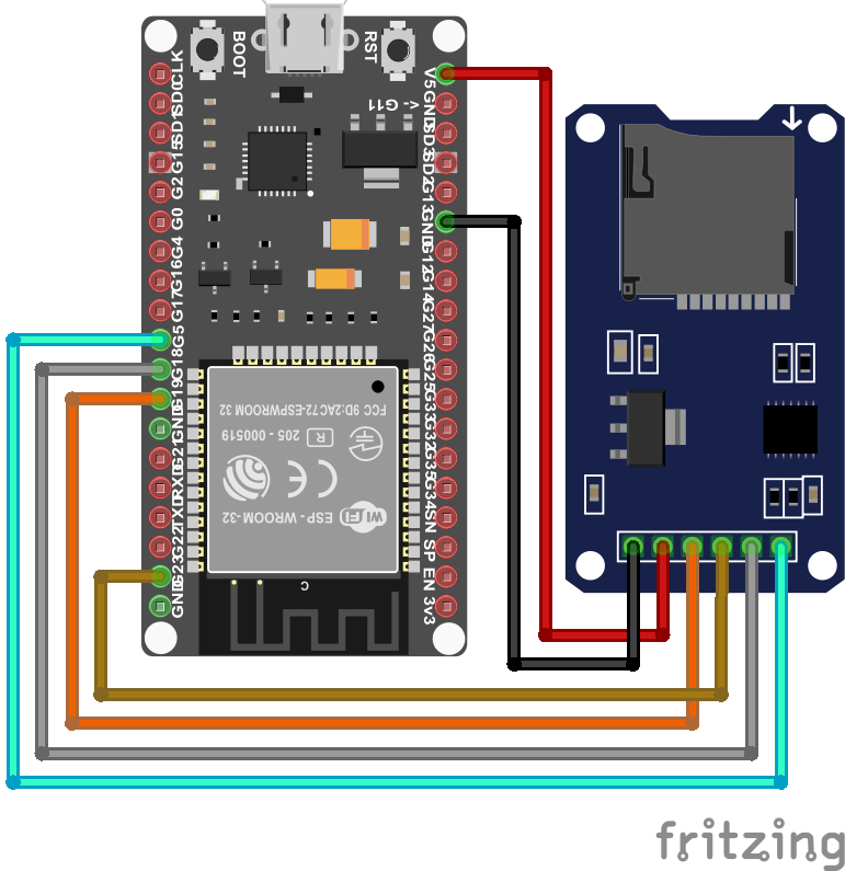
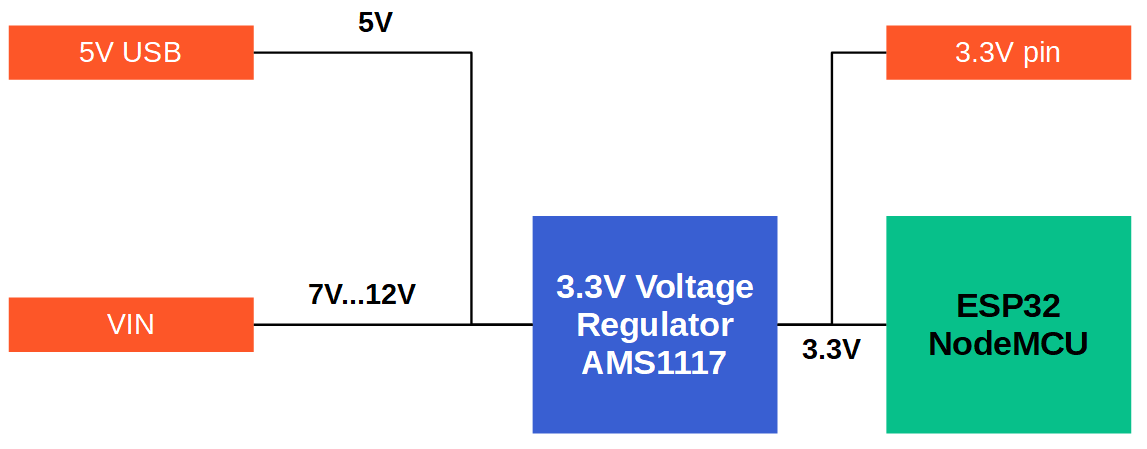
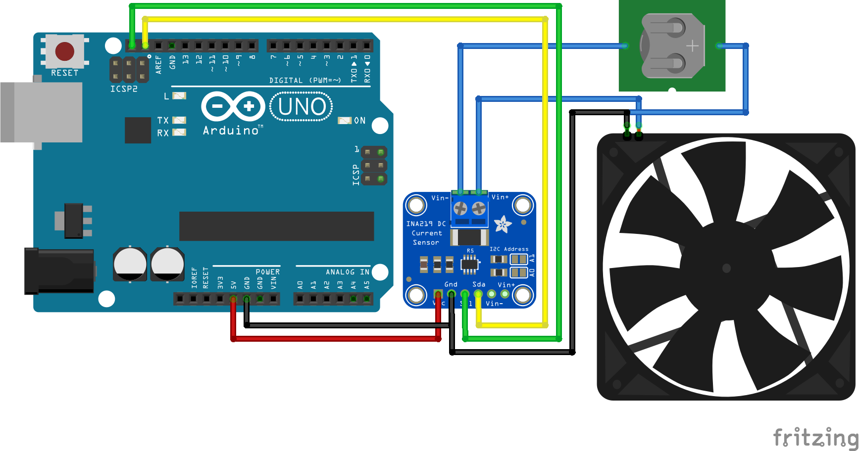
Wiring for all measurements
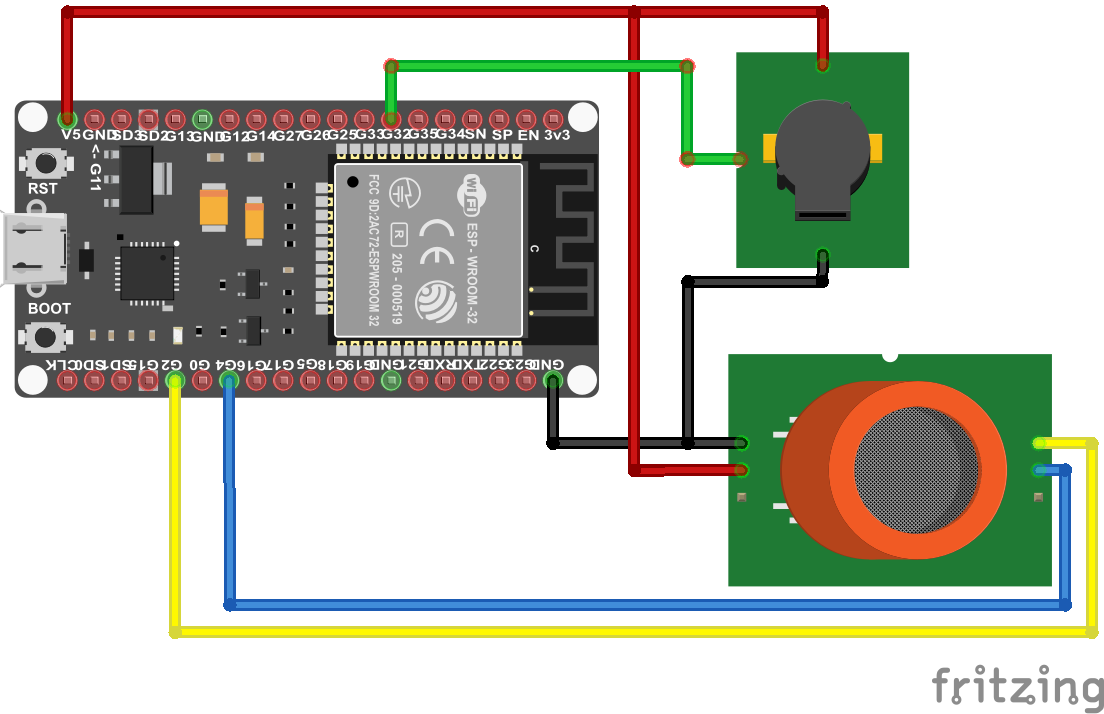
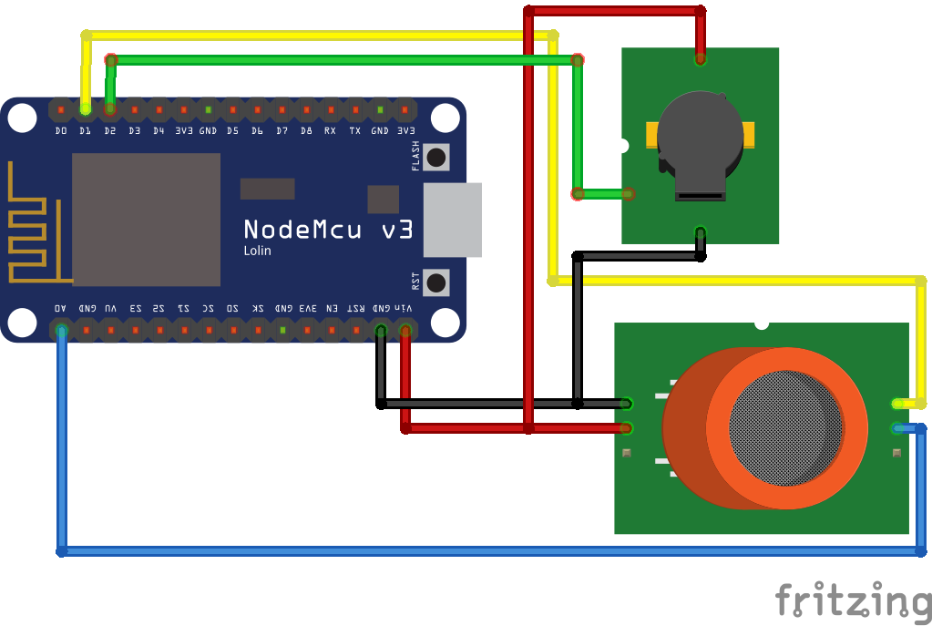
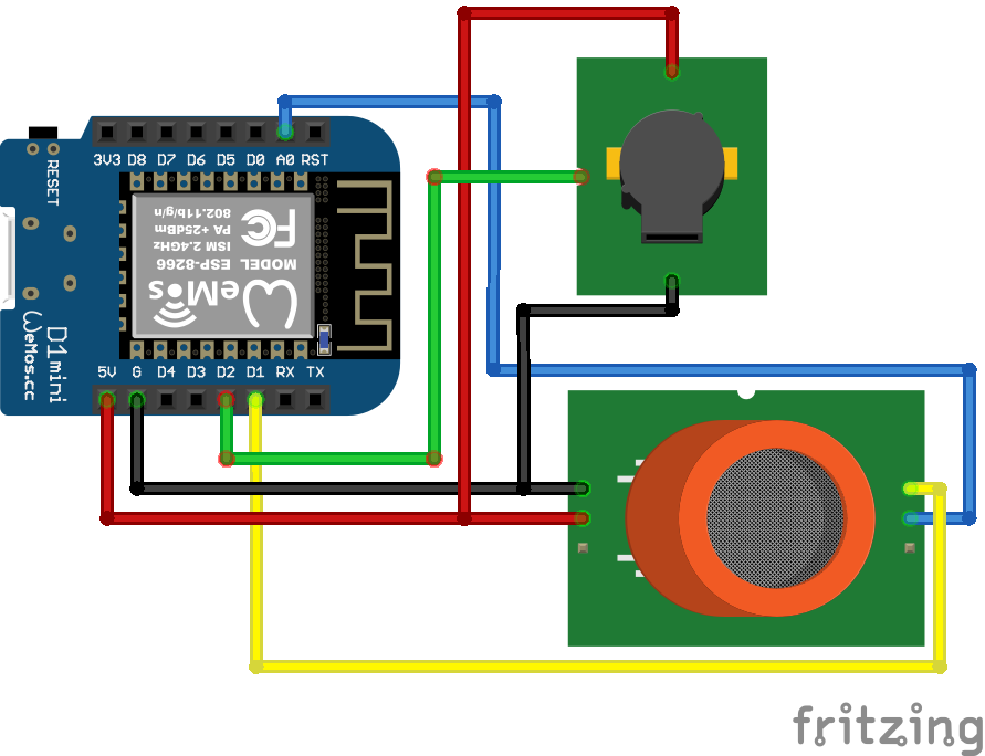
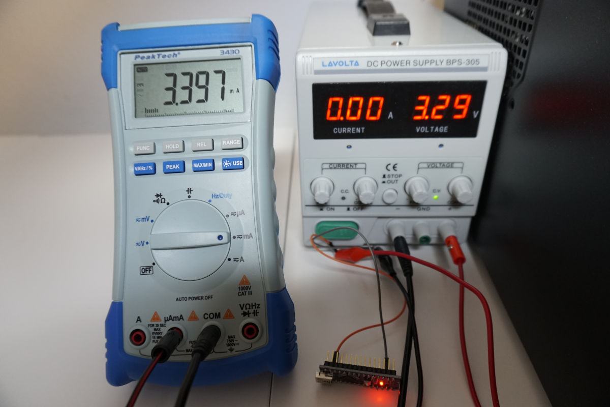
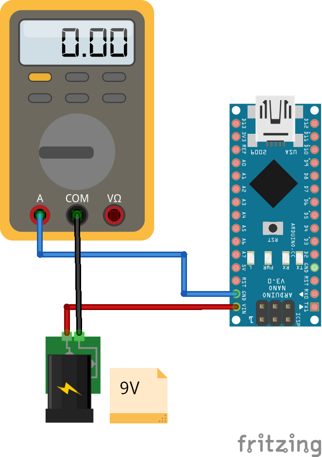
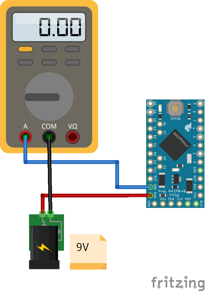
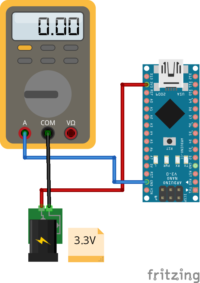
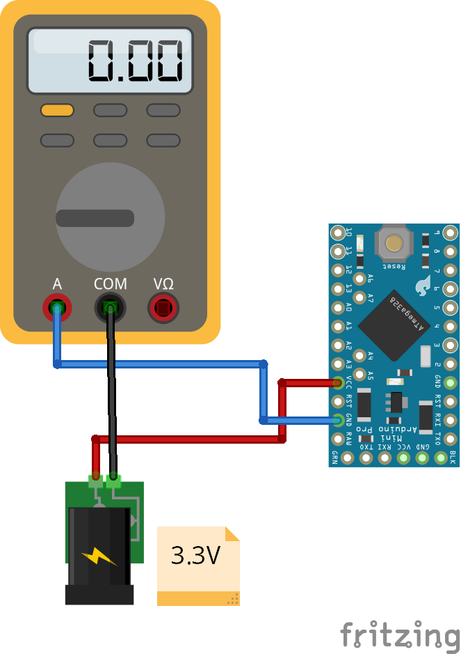
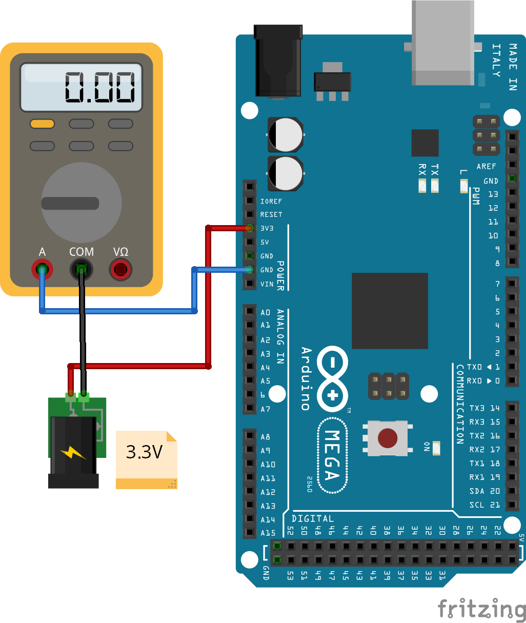
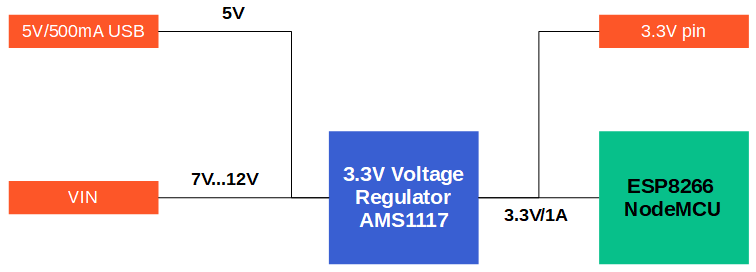
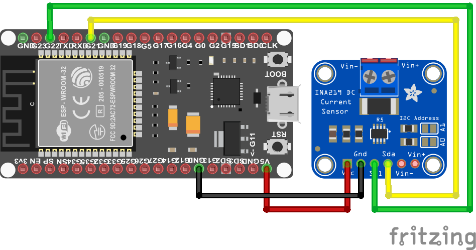
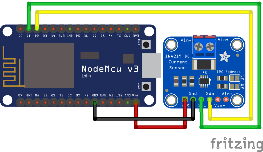
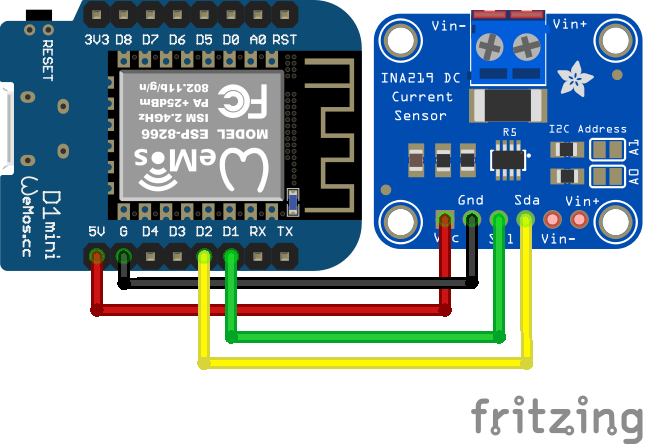
First of all it is important to know to measure the current consumption of each microcontroller. The following picture shows the wiring between all components.
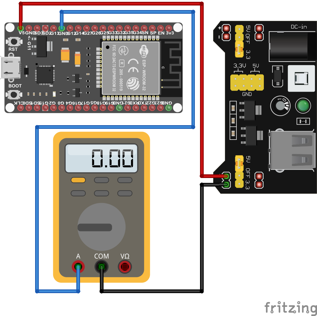
In my experiment I use my laboratory power supply that powers the ESP32 board with a constant voltage of 5V. The ESP32 boards have an input pin, that allows you to power the board with different voltage ranges that all support 5V. This input pin is connected to the voltage outlet of the power bench.
Next the ground (GND) pin of the ESP32 board is connected to the input of my multimeter that measures the current flow of the circuit. You can use your multimeter of choice, but I use my PeakTech 3430 that has an USB port to connect the multimeter the PC to record the measurements. To close the circuit, the output of the multimeter is wired with the ground pole of the laboratory power supply.
For the ESP32 – DevKitC and the Sparkfun ESP32 Thing, I had to push the reset button on the microcontroller board to get the boards running for the sleep modes. You only have to power the boards from the power bench and reset the board once.
For the ESP32 – DevKitC only measurements in the amp-mode not the milliamp-mode were possible.
Step 1) Use an ESP32 board with an optimized power consumption
There are many different ESP32 boards on the market and some of them are already optimized for low power consumption. Therefore the first step is to make sure that you buy an ESP32 board that has a lower power consumption than the average board.
The following table shows the six different ESP32 boards that I used for this tutorial with the build in microcontroller and the pins that are used for the current measurement.
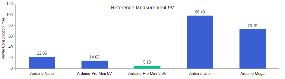
The ESP32 boards have a different power consumption that we want to measure as reference. For the reference power measurements I uploaded an empty program on the microcontroller as well as the ESP32 example script that uses the board as WiFi scanner.
The following picture shows the power consumption of the empty script.
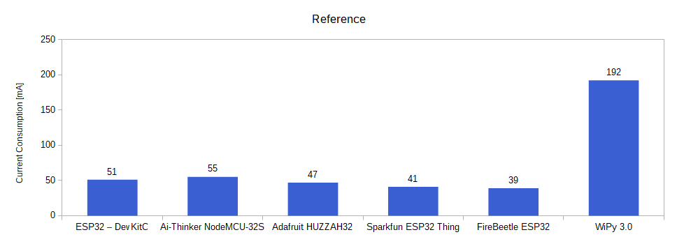
The current consumption of the WiPy 3.0 is 192mA that is much higher than the current consumption of the other ESP32 boards that are between 39mA and 55mA. The reason for this is, the WiPy 3.0 creates a local WiFi when it starts that consumes a lot of power.
It is important to know that the WiPy 3.0 is not a standard ESP32 microcontroller, because the board does not support the Arduino IDE and has to be programmed with MicroPython. If you are not familiar with MicroPython, you will need a lot of time to get the WiPy 3.0 running for you project.
The FireBeetle ESP32 has the lowest power consumption with 39mA for the empty script.
Next we want to see how high is the current consumption when the microcontroller runs the WiFi scanner example script. Because the example script is from the Arduino IDE, and the WiPy 3.0 does not support to Arduino IDE, the following measurement was not done for the WiPy 3.0.
The following picture shows the mean current consumption for the WiFi scanner example script.
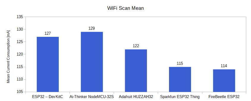
Like in the previous measurement, the Ai-Thinker NodeMCU-32S has the highest consumption with 129mA and the FireBeetle ESP32 has the lowest power consumption with 114mA.
But how is it possible that the power consumption differs between the ESP32 boards that are all based on the same microcontroller?
There are two main differences in the ESP32 boards. The first one is, the used voltage regulator and its efficiency. The second difference is if the boards using the ESP32 microcontroller or the ESP32-S2 microcontroller. Lets dive deeper into the different voltage regulators and the difference between the ESP32 and the ESP32-S2 microcontroller.
Voltage Regulator
The objective of the voltage regulator on the ESP32 board is to provide a stable 3.3V operation voltage for the ESP32 chip. Therefore the input voltage of the board is transformed and the energy resulting from the difference between the input voltage and the 3.3V operation voltage is transformed into heat.
Also if the voltage regulator does not perform any work, the regulator consumes a quiescent current, also called standby current. The lower the quiescent current of the voltage regulator, the more efficient the ESP32 board is and the less power the board consumes.
The dropout voltage is the difference between the output voltage and the input voltage at which the voltage regulator stops working. In the case of the ESP32 boards, the input voltage has to be higher than 3.3V + dropout voltage of the voltage regulator. The lower the voltage dropout, the longer your ESP32 board operates while powered by a battery, because during the discharging of the battery, the battery voltage drops.
The following table shows the different ESP32 boards with the used voltage regulator, the maximum voltage dropout and the quiescent current.
The ESP32 – DevKitC and the Ai-Thinker NodeMCU-32S both use the AMS1117 voltage regulator that has the highest voltage dropout of 1.1V at 800mA and also the highest quiescent current of 5mA.
The Adafruit HUZZAH32 and the Sparkfun ESP32 Thing have the AP2112-3.3 build in, that has a lower maximum voltage dropout of 0.4V at 600mA and also a lower quiescent current of 80µA and therefore should have an advantage for a lower power consumption.
The best voltage regulator for low power consumption has the FireBeetle ESP32, that uses the RT9080-33GJ5 voltage regulator with only 0.31V dropout voltage at 600mA and an ultra low quiescent current of only 4µA.
For the WiPy 3.0 I found no information which voltage regulator is used on this ESP32 board. Therefor I have no information about the maximum voltage dropout and quiescent current.
ESP32 vs ESP32-S2
Also the build in ESP32 microcontroller has an influence of the power consumption in general. There is the first generation of the ESP32 microcontroller and the second generation, called ESP-S2. The following table shows the important differences regarding to the power consumption.
You find detailed information about the microcontroller in the ESP32 datasheet and the ESP32-S2 datasheet.
The first generation of ESP32 microcontroller was released in 2016 by Espressif that use the Xtensa single/dual-core 32-bit LX6 microcontroller. If the single core is active, the clock frequency is 160 MHz and if the ESP32 runs in dual-code mode, the clock frequency is 240 MHz.
The second generation, called ESP32-S2 was released in 2019 and has a fast single core microcontroller build in, the Xtensa single-core 32-bit LX7 and also a much more powerful co-processor.
Because the ESP32-S2 co-processor is based on the RISC-V architecture, the power consumption is much lower. The ULP co-processor is active when the CPU is disabled in sleep-modes and consumes a lot less power then the CPU.
Moreover the ESP32-S2 is able to turn off the WiFi transceiver when not in use to save more power but the WiFi is still enabled. This function is very useful when your project does not allow to enter the deep-sleep mode because the ESP32-S2 can hold the WiFi connection to the router.
The following table shows the current consumption of the ESP32 and ESP32-S2 in the different power modes.
It is important to understand that this current consumption is measured under perfect conditions and only for the blank microcontroller and not the whole board with the ESP32 build in. Therefor the comparison gives us a good indication if an ESP32 board with an ESP32 or an ESP32-S2 has an advantage regarding a low power consumption.
Because we also see a strong dependency between the power consumption and the power modes, we take a deep dive into the different power modes of the ESP32 microcontroller.
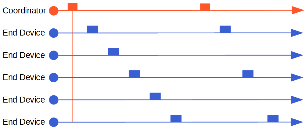
Step 2) Use the ESP32 Power Modes
The ESP32 and the EPS-S2 have the same power modes that use advanced power management technologies. In the following section of this guide we describe each power mode, see what parts of the microcontroller are active or inactive and also how to enter each power mode with Arduino code or for the WiPy 3.0 with the code in MicroPython.
There are different wake up sources for the ESP32 to come back from the power saving mode. Because we want to focus on the power consumption, we do not dive deep into the different wake up sources. Therefore, in the following section, I only use the timer to define a specific time when the ESP32 wakes up again. You find detailed information of the sleep modes as well as all wake up sources in the Espressif docs.
Because the ESP32 is a 32-bit microcontroller, the maximum time for every sleep mode is the maximum value for a 32-bit unsigned integer that is 0xFFFF FFFF or 4294967295 microseconds that equals around 71 minutes.
Modem-Sleep
Inactive
WiFi
Bluetooth
Radio
Peripherals
Active
ESP32 Code
ULP Co-Processor
RTC
In the modem-sleep power mode, the CPU is powered and the ESP32 is switching between active mode and modem-sleep depending on the usage of the WiFi communication. The switching is done automatically and also the CPU frequency is changed automatically, depending on the CPU load and the use of the peripherals.
Because the ESP32 is entering the modem-sleep power mode automatically, there is no Arduino function to enter this power mode.
Light-Sleep
Inactive
WiFi
Bluetooth
Radio
Peripherals
Paused
ESP32 Code
Active
ULP Co-Processor
RTC
The light-sleep mode only differs from the modem-sleep mode in the fact, that the ESP32 is not active but paused. That means that most of the RAM and the CPU are following a sleep pattern. In that pattern internal flip-flops do not switch states because this switching consumes power.
During the light-sleep mode, the WiFi baseband is disabled but the WiFi connection itself remains active.
We can enter the light-sleep mode with the following function: esp_light_sleep_start(void)
The following Arduino code shows how to enter the light-sleep mode
#define uS_TO_S_FACTOR 1000000ULL  /* Conversion factor for micro seconds to seconds */
#define TIME_TO_SLEEP  5        /* Time ESP32 will go to sleep (in seconds) */

void print_wakeup_reason(){
  esp_sleep_wakeup_cause_t wakeup_reason;
  wakeup_reason = esp_sleep_get_wakeup_cause();

  switch(wakeup_reason)
  {
    case ESP_SLEEP_WAKEUP_EXT0 : Serial.println("Wakeup caused by external signal using RTC_IO"); break;
    case ESP_SLEEP_WAKEUP_EXT1 : Serial.println("Wakeup caused by external signal using RTC_CNTL"); break;
    case ESP_SLEEP_WAKEUP_TIMER : Serial.println("Wakeup caused by timer"); break;
    case ESP_SLEEP_WAKEUP_TOUCHPAD : Serial.println("Wakeup caused by touchpad"); break;
    case ESP_SLEEP_WAKEUP_ULP : Serial.println("Wakeup caused by ULP program"); break;
    default : Serial.printf("Wakeup was not caused by deep sleep: %d\n",wakeup_reason); break;
  }
}

void setup(){
  Serial.begin(9600);
  while (!Serial) {
    ; // wait for serial port to connect. Needed for native USB
  }
}

void loop(){
  print_wakeup_reason(); //Print the wakeup reason for ESP32

  delay(5000);

  esp_sleep_enable_timer_wakeup(TIME_TO_SLEEP * uS_TO_S_FACTOR); // ESP32 wakes up every 5 seconds

  Serial.println("Going to light-sleep now");
  Serial.flush();
  esp_light_sleep_start();
}
In the first part of the Arduino script we define two variables to store
- a factor to convert the time from micro seconds to seconds
- the time in seconds the ESP32 should go into the light-sleep mode
The second step is to define a function, called print_wakeup_reason, that tells us the wake up reason for the ESP32. This function is optional and is not needed to get the ESP32 into any power mode. In the function we get the wake-up source which caused wake up from sleep and store the source in the variable wakeup_reason. In the following switch case section, we test all possible wake up sources and print the source for the EPS32 to wake up in the serial monitor.
In the setup function, we define a baud rate of 9600 that has to be the same as in the serial monitor in your Arduino IDE. Because it takes a short time to establish the serial connection between the ESP32 board and your PC via the USB connection, we use the while loop to make sure that your program only continues when the serial connection is ready.
When the serial connection is established, we start the loop function and print the wake-up reason to the serial monitor by calling the print_wakeup_reason function that we defined.
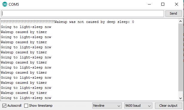
Now we want to go into the light-sleep power mode. Therefor we first have to define how we want to wake up. In my case I choose the timer for the wake-up and set the timer to 5 seconds.
Now we send the message that we are going to sleep and with the flush function, we wait until the data on the serial communication is sent and go to sleep by calling the esp_light_sleep_start function.
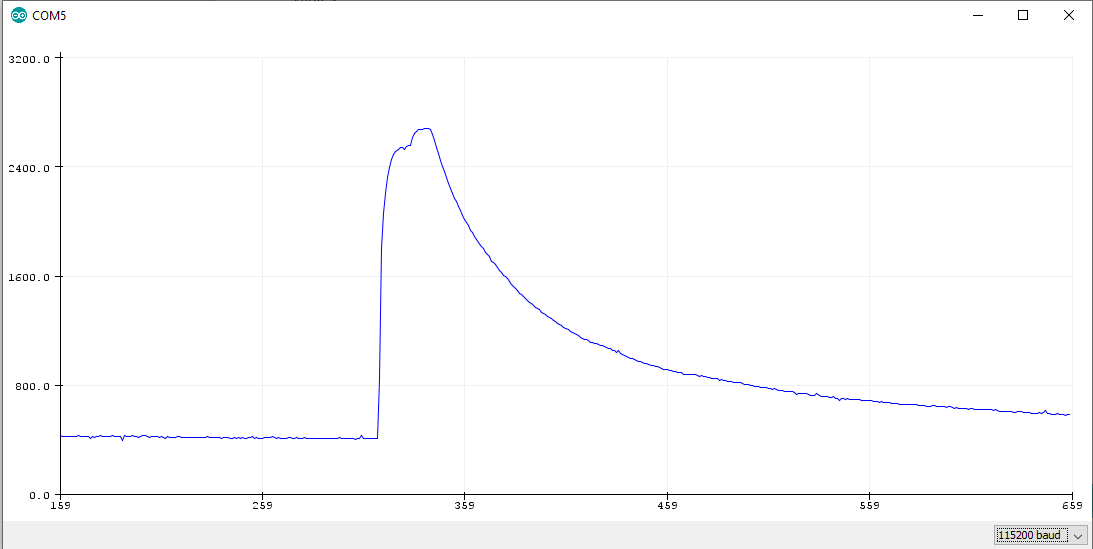
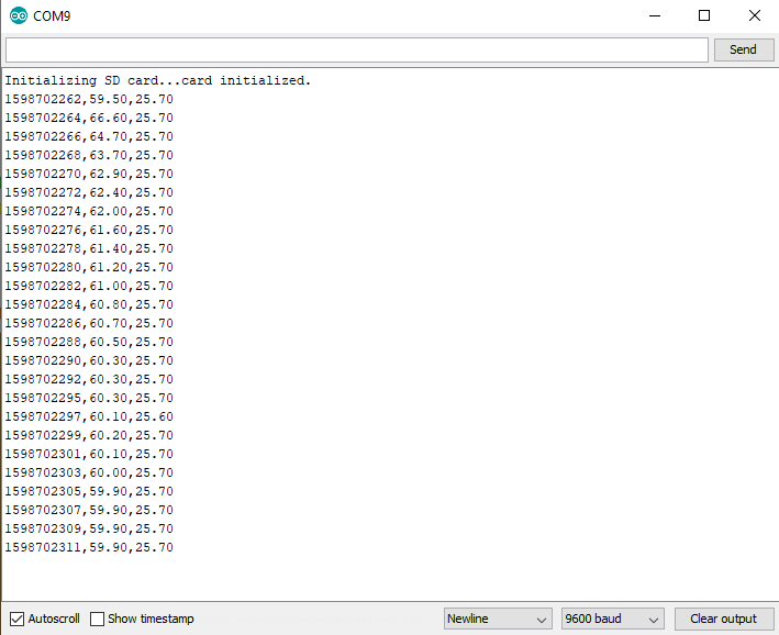
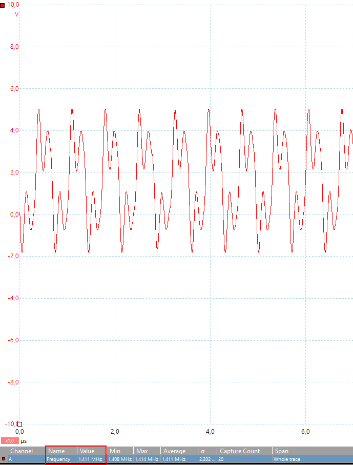
The serial monitor shows the following picture.
The WiPy 3.0 has a light-sleep mode, but in my case the power consumption was not reduced. Therefore the following bar-chart and the table show the power consumption in the light-sleep mode for the other ESP32 boards as well as the comparison to the reference measurement with an empty Arduino script.

Light-Sleep Multimeter Measurements
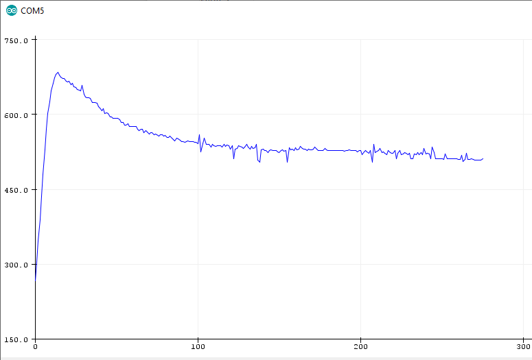
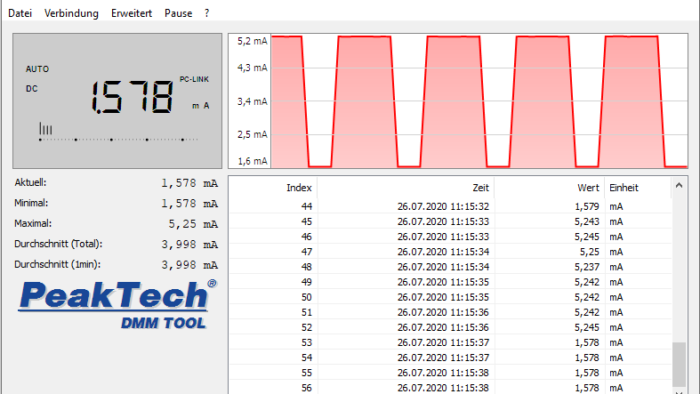
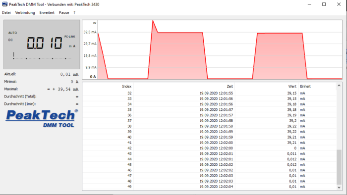
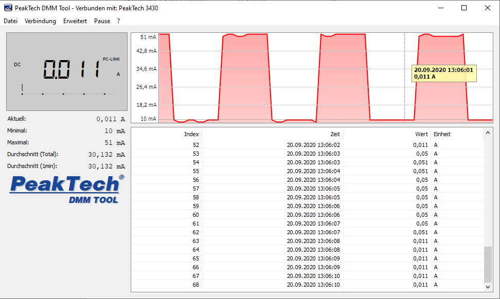
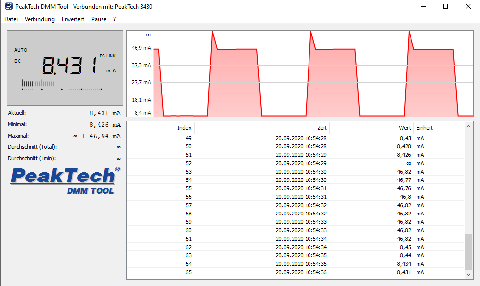
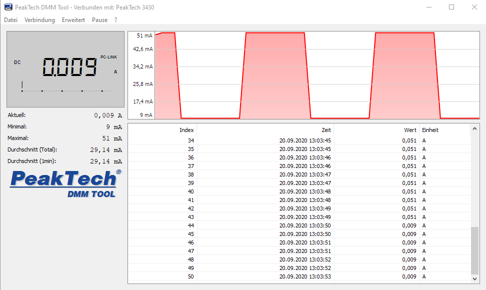
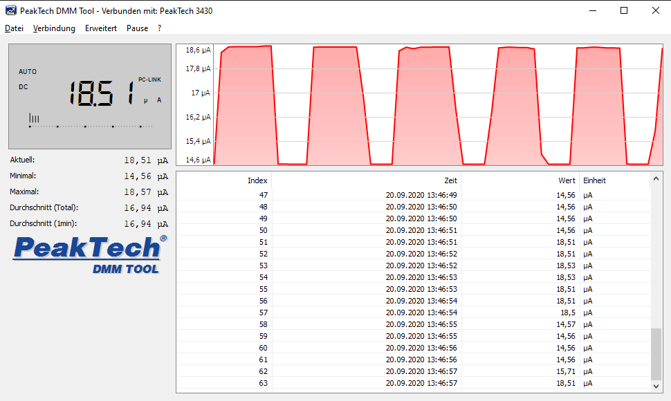
If you are interested in the measurements of the multimeter, the following pictures are direct screenshots of the current flow over time for each microcontroller board.
ESP32 – DevKitC LightSleep

Ai-Thinker NodeMCU-32S LightSleep
Adafruit HUZZAH32 LightSleep
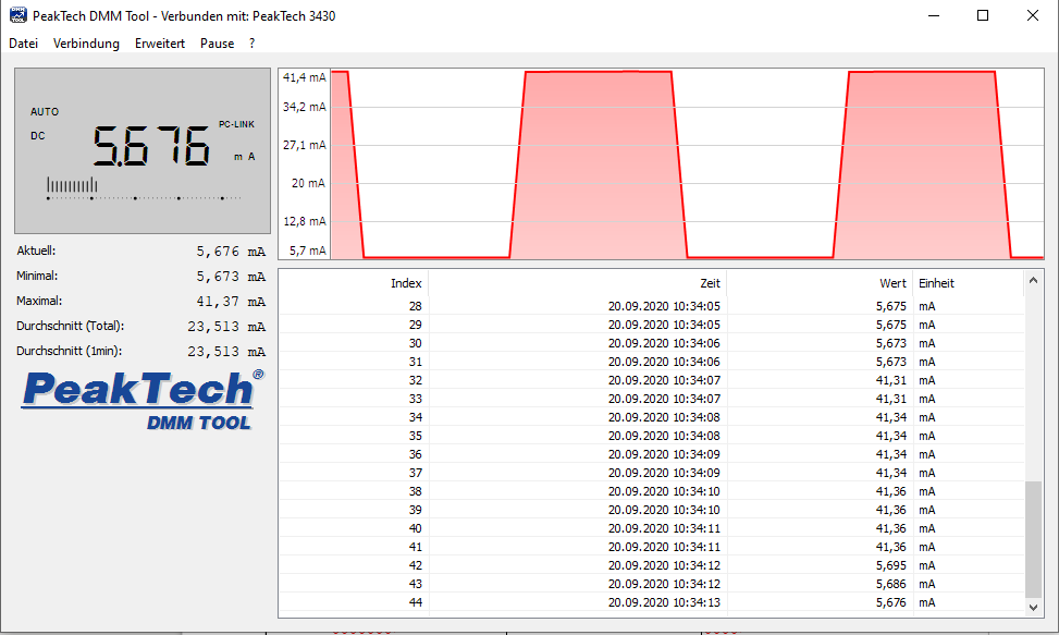
Sparkfun ESP32 Thing LightSleep
FireBeetle ESP32 LightSleep
The ESP32 board that consumes the most current in the light sleep mode is the Ai-Thinker NodeMCU-32S with 15.05mA, but compared to the reference measurement with the empty Arduino script the current reduction is -72,64%.
The highest overall percentage reduction and also the lowest power consumption absolute in the light-sleep mode has the FireBeetle ESP32 with 1.94mA (-95.03%).
All other ESP32 microcontroller based boards are able to lower their current consumption between 80% and 87%. Therefore if you can use the light-sleep mode in your project with a battery power supply, the lifespan of the battery is increased a lot.
Deep-Sleep
Inactive
ESP32 Core
WiFi
Bluetooth
Radio
Peripherals
Active
ULP Co-Processor
RTC
While in the light-sleep mode, the ESP32 Core is paused and following a sleep pattern, the ESP32 Core is completely inactive during the deep-sleep power mode. Only the ULP Co-processor and the RTC remains active.
During the deep-sleep mode, the WiFi connection is not active, but the WiFi configuration data is stored in the memory of the real time clock. Therefore the reestablishing of the WiFi connection after the ESP32 wakes up from deep-sleep mode is very quickly.
The following Arduino code shows you how to enter the deep-sleep mode. For the WiPy 3.0 you find the MicroPython code in the Pycom tutorials.
#define uS_TO_S_FACTOR 1000000  /* Conversion factor for micro seconds to seconds */
#define TIME_TO_SLEEP  5        /* Time ESP32 will go to sleep (in seconds) */

void print_wakeup_reason(){
  esp_sleep_wakeup_cause_t wakeup_reason;
  wakeup_reason = esp_sleep_get_wakeup_cause();

  switch(wakeup_reason)
  {
    case ESP_SLEEP_WAKEUP_EXT0 : Serial.println("Wakeup caused by external signal using RTC_IO"); break;
    case ESP_SLEEP_WAKEUP_EXT1 : Serial.println("Wakeup caused by external signal using RTC_CNTL"); break;
    case ESP_SLEEP_WAKEUP_TIMER : Serial.println("Wakeup caused by timer"); break;
    case ESP_SLEEP_WAKEUP_TOUCHPAD : Serial.println("Wakeup caused by touchpad"); break;
    case ESP_SLEEP_WAKEUP_ULP : Serial.println("Wakeup caused by ULP program"); break;
    default : Serial.printf("Wakeup was not caused by deep sleep: %d\n",wakeup_reason); break;
  }
}

void setup(){
  Serial.begin(9600);
  while (!Serial) {
    ; // wait for serial port to connect. Needed for native USB
  }

  print_wakeup_reason(); //Print the wakeup reason for ESP32

  delay(5000);

  esp_sleep_enable_timer_wakeup(TIME_TO_SLEEP * uS_TO_S_FACTOR); // ESP32 wakes up every 5 seconds

  esp_sleep_pd_config(ESP_PD_DOMAIN_RTC_PERIPH, ESP_PD_OPTION_ON); // all RTC Peripherals are powered

  Serial.println("Going to deep-sleep now");
  Serial.flush();
  esp_deep_sleep_start();
}

void loop(){
}
Most of the Arduino code is the same compared to the light-sleep code. We define the same variables and the function to print the wake-up reason.
Because the ESP32 starts the setup function every time the microcontroller wakes up from deep-sleep mode, we define all of our code in the setup function and do not use the loop function.
After setting the baud rate and wait for the serial communication, the function for the wake up reason is called. Like the light-sleep mode, we define that the EPS32 should wake-up when the timer has expired.
For the deep-sleep mode, we can define if all RTC peripherals are active or powered down. In the sleep configuration file we define that the RTC modules like RTC IO, sensors and the ULP co-processor remains active.
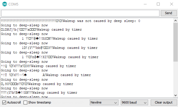
The deep-sleep power mode starts with the function esp_deep_sleep_start. The following picture shows the serial monitor for the deep-sleep Arduino script.
Like for the light-sleep mode, we want to know how much current each ESP32 board consumes during the deep-sleep phase and also if we could further reduce the power consumption. The following bar-charts shows the current consumption for all ESP32 boards during the deep-sleep phase.
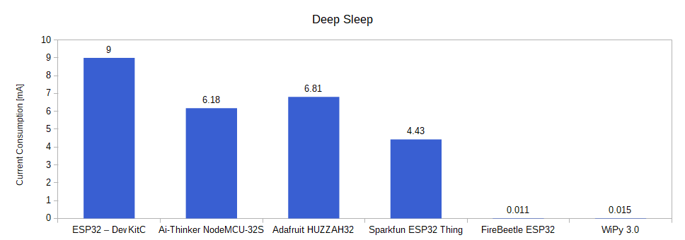
The following table shows the comparison of the deep-sleep current consumption compared to the reference measurement.
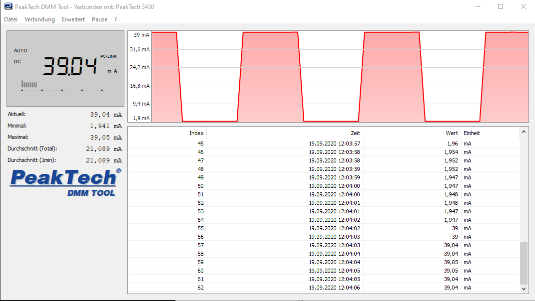
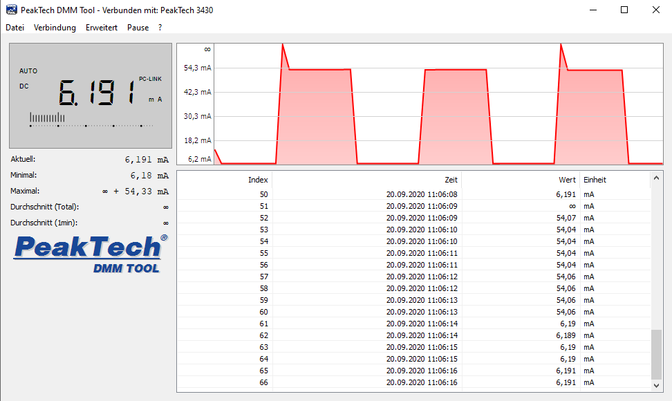
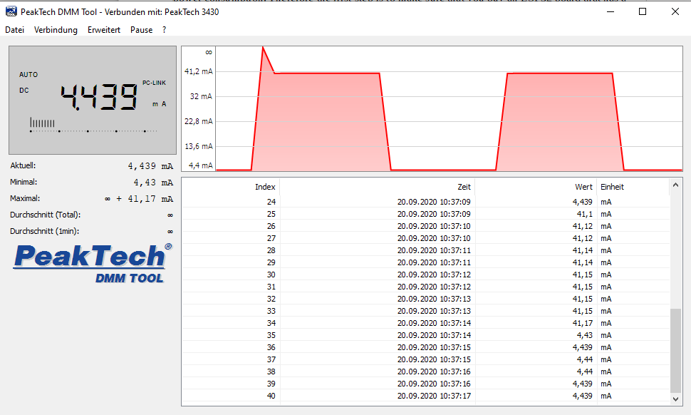
Deep-Sleep Multimeter Measurements
The following pictures of the multimeter shows the verification for each microcontroller board.
ESP32 – DevKitC DeepSleep
Ai-Thinker NodeMCU-32S DeepSleep

Adafruit HUZZAH32 DeepSleep
Sparkfun ESP32 Thing DeepSleep
FireBeetle ESP32 DeepSleep
WiPy 3.0 DeepSleep
Now we can see which ESP32 boards take the minimal power consumption serious. The FireBeetle ESP32 and the WiPy 3.0 consumes less than 0.015mA in the deep-sleep mode. All other boards have a more than 400 times higher current consumption.
One reason for the lower current consumption are the build in voltage regulators that have a lower quiescent current.
Hibernation
Inactive
ESP32 Core
ULP Co-Processor
WiFi
Bluetooth
Radio
Peripherals
Active
RTC
The Hibernation power mode is the power mode with the lowest current consumption. A blank ESP32 microcontroller consumes only 5µA. The internal 8-MHz oscillator and ULP co-processor are disabled and the RTC recovery memory is powered down. Only one RTC timer on the slow clock and certain RTC GPIOs are active. The RTC timer or the RTC GPIOs can wake up the chip from the Hibernation mode
To enter the Hibernation power mode we use the same Arduino script like the deep-sleep mode, but we select that all RTC peripherals are deactivated. Therefore we only change the sleep configuration file to:
esp_sleep_pd_config(ESP_PD_DOMAIN_RTC_PERIPH, ESP_PD_OPTION_OFF);
The WiPy 3.0 does not have the option to enter the hibernation power mode and is therefore not considered in this power mode.
The following bar-chart and table shows the power consumption of the ESP32 boards during the hibernation mode.
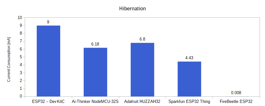
From the data, you see that there are only minor changes compared to the deep-sleep mode. However for the Adafruit HUZZAH32 and the FireBeetle ESP32, the current consumption can be further reduced via the hibernation mode. For the ESP32 – DevKitC, Ai-Thinker NodeMCU-32S and Sparkfun ESP32 Thing, the measurement shows no difference.
Step 3) Increase the Sleep Time
We have gained two important insights from the last chapter, which help us to further reduce the power consumption of our entire ESP32 project.
- Establishing a WiFi connection and sending data via WiFi have a very high power consumption
- In Dee-Sleep or hibernation mode, the power consumption of the ESP32 is significantly lower.
Therefore the power consumption can be reduced if the individual phases (awake, send data via WiFi, sleep) are planned precisely.
The individual phases can be clearly described using the example of a weather station:
The ESP32 is connected to a DHT22 temperature and humidity sensor. If we transmit the temperature and humidity every 10 seconds, the power consumption will be unnecessarily high, because mostly the same measured values are transmitted.
The power consumption can be reduced by transmitting readings only every 10 minutes instead of every 10 seconds. With this we have extended the sheep time. To reduce the number of WiFi connections, each time you wake up from sleep mode, the current sensor values can be compared with the last values sent, to send new data via WiFi only if the temperature or humidity has changed.
To store variables across sleep mode, they must be loaded into the RTC memory, which is only 8kB on ESP32. You only have to add RTC_DATA_ATT in front of the variable.
RTC_DATA_ATT int temperature;
RTC_DATA_ATT int humidity;
Summary: Reduce the ESP32 Power Consumption
The following table shows the overview of all measurements that I made for the 6 different ESP32 boards. The empty Arduino script is the reference measurement for all boards. It should be noted that WiPy 3.0 sets up a local WiFi by default and that this is why the power consumption in the reference measurement is much higher compared to the other ESP32 boards.
If we compare the ESP32 – DevKitC and the Ai-Thinker NodeMCU-32S that only have the mayor difference in the version of the ESP32 chip, we see that the ESP32-S2 helps to reduce the power consumption in the deep-sleep mode and hibernation mode from 9mA to 6.18mA.
The Adafruit HUZZAH32 has a build in voltage regulator with a higher efficiency but not the ESP32-S2. Therefore the current consumption is lower than the ESP32 – DevKitC but higher compared to the Ai-Thinker NodeMCU-32S.
Interesting is, that the Sparkfun ESP32 Thing uses the same voltage regulator and the same ESP32 microcontroller than the Adafruit HUZZAH32 but has a significant lower power consumption:
- Reference: -12.77%
- Light sleep: -32.74%
- Deep-sleep: -34.95%
- Hibernation: -34.85%
Therefore we know, that the voltage regulator and the ESP32 microcontroller are not the only factors influencing the power consumption of the ESP32 board.
If you are looking for a ESP32 board that consumes really little current, I recommend to use the FireBeetle ESP32 if you are familiar with the Arduino IDE and their libraries. But if you want to try something new and you are familiar with MicroPython, you can also use the WiPy 3.0 for a low power project.
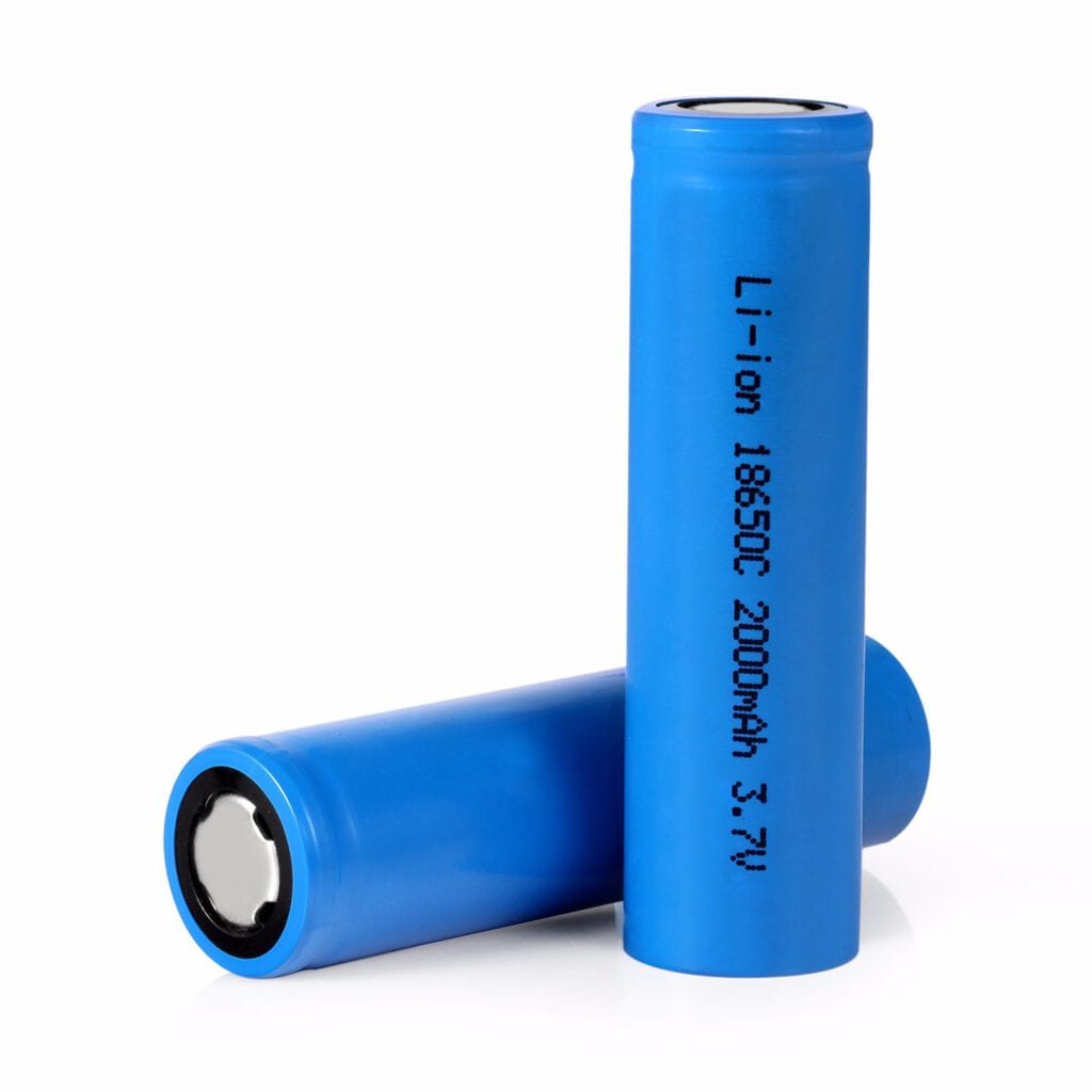
If you want to use a battery for the power supply of the microcontroller board, the FireBeetle ESP32 has a standard 2-pin JST connector. If you want to connect a Lithium Ion Battery with JST connector to the WiPy 3.0, you have to use the an extension board like the Expansion Board 3.0.
If you have any questions regarding the ESP32 power consumption in general or the different low-power modes, use the comment section below to ask your question. I will answer them as soon as possible.
I have also a tutorial to reduce the ESP8266 or Arduino power consumption.