INA219 Tutorial for Arduino, ESP8266 and ESP32
The INA219 is a current and voltage sensor that you use with any Arduino, ESP8266 or ESP32 microcontroller.
You can measure up to 26 volts and use the I2C communication to transfer data to the microcontroller.
In this tutorial I use the INA219 to measure the discharging curve of a battery that is connected to a fan.
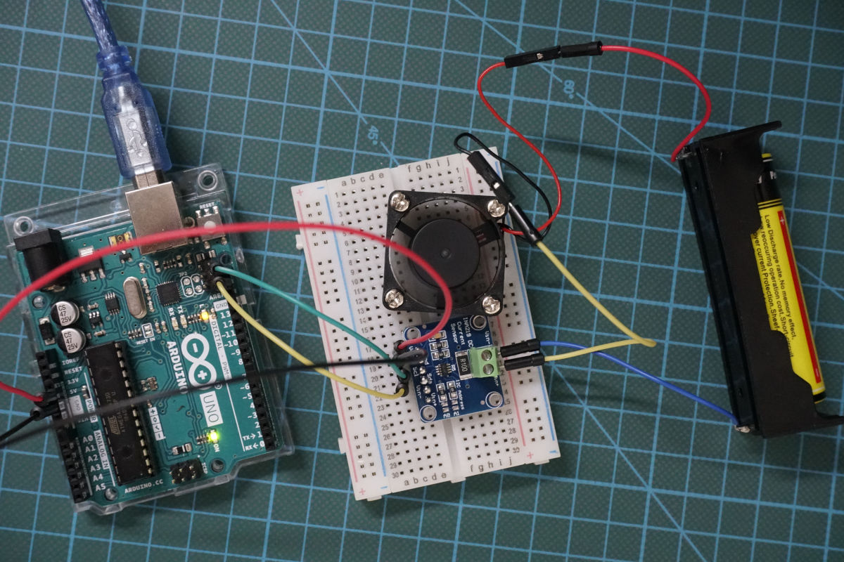
Table of Contents
How does the INA219 sensor work?
Before we can use the INA219, we have to make sure that we understand how the sensor is working. To describe the functionality of the sensor, we go step by step over the simplified schematic of the INA219 which you see in the following picture.
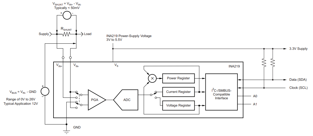
The INA219 sensor has a 2-pin screw-terminal, connected to the high side of the measuring in series, able to measure voltages up to 26V. The screw-term is connected to a 0.1 ohm 1% sense shunt resistor in parallel. The INA219 measures two different voltages at the high side:
- V_shunt is the voltage drop across the shunt resistor.
- V_bus is the voltage from the negative pole with respect to ground.
Both voltages are then forwarded to the Programmable Gain Amplifier (PGA) to increase the sensitivity of the measurement. The INA219 increases the full-scale range up to 2, 4 or 8 times (320mV). Also the bus voltage measurements has two ranges: 16V or 32V.
After the sensitivity of the voltage measurement is increased, the current and also the power is calculated. The following picture shows how the calculation is done based on the shunt and bus voltage.
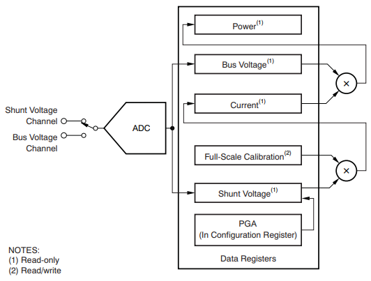
The current flow on the high side of the measurement is calculated by multiplying the shunt voltage with the calibrated resistance of the shunt resistor. Because the shunt resistor is 0.1 ohm and the maximum shunt voltage at the scale of 8 is 320mV, the maximum current that can be measured is 320mV / 0.1 ohm = 3.2A.
Then the power is calculated with this current multiplied with the bus voltage. Based on the maximum current of 3.2A and a maximum bus voltage of 26V, the INA219 can measure up to 3.2A * 26V = 83W of power.
Therefore the INA219 is able to provide four different measurements:
- Shunt voltage: voltage drop across the shunt resistor
- Bus voltage: total voltage seen by the circuit under test. (supply voltage – shunt voltage).
- Current: derived via Ohms Law from the measured shunt voltage
- Power: current multiplied by the bus voltage
Each of the measurements and calculations are stored in a register that is connected to the I2C interface to forward the values to the Arduino or ESP microcontroller. If you want to know how I2C is able to transfer data between electrical devices, I recommend my I2C tutorial.
The Arduino, ESP8266 or ESP32 microcontroller powers the INA219 either with 3.3V or 5V.
Now we know the basic functionality of the INA219 voltage sensor but if you are interested in more details of the sensor, visit the product description of Texas Instruments.
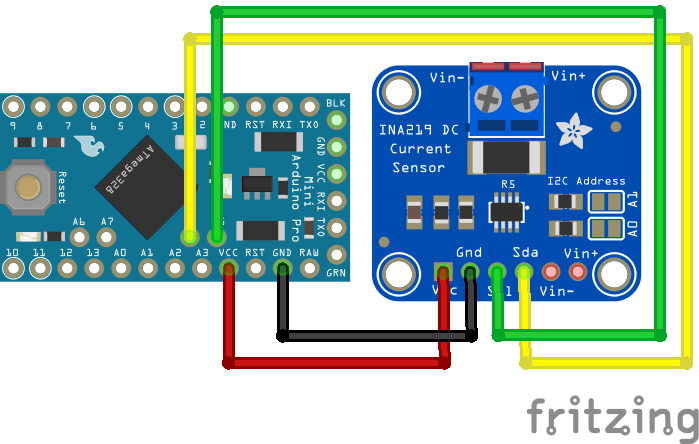
Connecting the INA219 to Arduino, ESP8266 and ESP32 microcontroller
The wiring of the INA219 is shown in the following pictures for different Arduino, ESP8266 and ESP32 microcontroller. If you are missing a microcontroller, please write a comment in the section below this article and I will add more fritzing pictures of the wiring of the INA219.
In my case I powered the INA219 from the microcontroller with 5V but you can connect also the 3.3V instead. Also you have to connect the clock (SCL) and data (SDA) pins for the I2C communication to send the information about voltage, current and power from the INA219 to the microcontroller.

INA219 Arduino Nano
INA219 Arduino Pro Mini
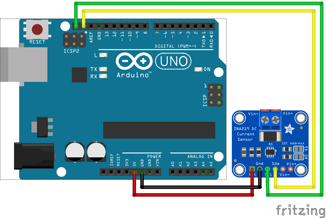
INA219 Arduino Uno
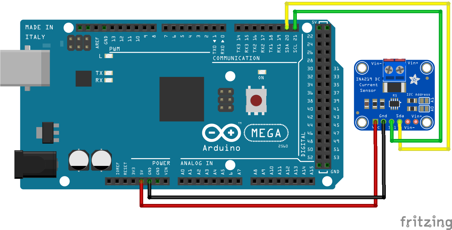
INA219 Arduino Mega
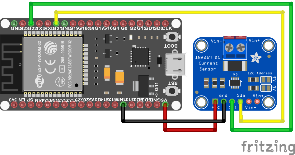
INA219 ESP32 NodeMCU
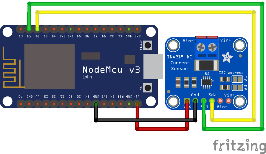
INA219 ESP8266 NodeMCU
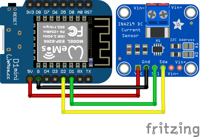
INA219 ESP8266 WeMos D1 Mini
If you do not know which pins of your microcontroller are the I2C pins, you can visit the pinout articles where you find an overview of all pins of the corresponding microcontroller. I created pinout articles for the following microcontroller:
Find the INA219 I2C Address
In order to communicate with the INA219 via I2C, you have to know the I2C address of the electrical device, because each device gets its own unique address in a I2C network. The default I2C address of the INA219 is 0x40 and is important for the later Arduino script.
If you are not sure if your sensor has the I2C address 0x40, I created an I2C scanner that requires no additionally hardware and finds the address of all connected I2C devices.
But what do you do if you want to use two voltage and current sensors and read the values of both sensors with one Arduino or ESP microcontroller? By default both sensors have the I2C address 0x40 but the I2C address has to be unique. Therefore on the right side of the INA219 you see two different contact pairs next to two resistors. The following picture shows the contacts of the voltage and current sensor.
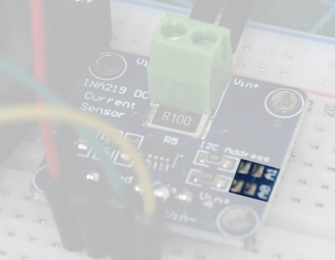
Depending on the contact you bridge by soldering the contacts, the I2C address changes. Therefore you can use up to four different INA219 boards in one I2C network. The following table shows the four different boards, their I2C address and what contacts have to be bridged. The top contact is A1 and the bottom contact is A0.
Record the Discharging Curve of a Battery
The following table gives you an overview of all components and parts that I used for this tutorial. I get commissions for purchases made through links in this table.
In the following example I want to measure the discharging curve of a Lithium Ion battery. The battery is powering a fan. I want to know how the discharging curve of the battery look like. Therefore I measure the voltage, current and power from the battery.
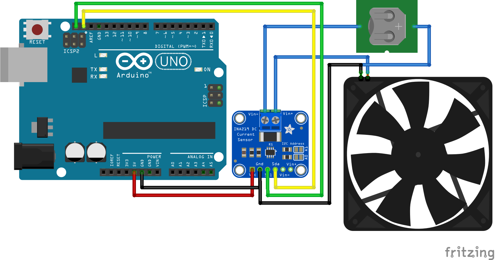
The following picture shows the circuit with all components for the Arduino Uno. If you have any other microcontroller, you find the wiring in the previous chapter for other Arduino, ESP8266 and ESP32 microcontroller.
After we connected all parts lets dive into the program script that I explain step by step. For the Arduino script we use the Adafruit_INA219 library that you can install over the Arduino IDE. If you do not know how to install a library, you find a step by step tutorial in the Arduino library article.
#include "Wire.h"
#include "Adafruit_INA219.h"

Adafruit_INA219 ina219;

void setup() {
  // Open serial communications and wait for port to open:
  Serial.begin(9600);
  while (!Serial) {
    ; // wait for serial port to connect. Needed for native USB port only
  }

  if (! ina219.begin()) {
    Serial.println("Failed to find INA219 chip");
    while (1) { delay(10); }
  }

  Serial.print("BV"); Serial.print("\t"); // Bus Voltage
  Serial.print("SV"); Serial.print("\t"); // Shunt Voltage
  Serial.print("LV"); Serial.print("\t"); // Load Voltage
  Serial.print("C"); Serial.print("\t");  // Current
  Serial.println("P");  // Power
}

void loop() {
  float shuntvoltage = 0;
  float busvoltage = 0;
  float current_mA = 0;
  float loadvoltage = 0;
  float power_mW = 0;

  shuntvoltage = ina219.getShuntVoltage_mV();
  busvoltage = ina219.getBusVoltage_V();
  current_mA = ina219.getCurrent_mA();
  power_mW = ina219.getPower_mW();
  loadvoltage = busvoltage + (shuntvoltage / 1000);

  Serial.print(busvoltage); Serial.print("\t");
  Serial.print(shuntvoltage); Serial.print("\t");
  Serial.print(loadvoltage); Serial.print("\t");
  Serial.print(current_mA); Serial.print("\t");
  Serial.println(power_mW);

  delay(1000);
}
The first part of the script is to include the Wire and Adafruit INA219 library. The Wire library enables the microcontroller to use the I2C communication because the INA219 current and voltage sensor is connected to the microcontroller via I2C. The Adafruit INA219 library makes the handling of the sensor itself easier because we only need to use one function for each measurement.
After the two libraries are included, the Adafruit INA219 object is created with the name ina219.
In the setup function we open the serial communication with the baud rate of 9600 because I want to display the measurements to the serial monitor of the Arduino IDE. Also with the while loop we wait until the serial port is connected.
In the second part of the setup function the INA219 object is initialized with the begin function and if the object could not be initialized, we know that something with the chip is wrong. Therefore we print this error message to the serial output.
In the last part of the setup function a table is created with all measurements we want to print. The table is build with tabulator spaces that enables me to copy all measurements to Excel and create different charts that you see at the end of this tutorial.
The loop function starts with creating float variables for each measurement that are all set to zero.
- Shunt voltage measured in millivolt
- Bus voltage measured in volt
- Load voltage calculated in volt
- Current calculated in milliamps
- Power calculated in milliamps
Now every variable is filled by the get function of the Adafruit INA219 library but the load voltage is calculated by adding the shunt voltage to the bus voltage. The deviation with 1000 is only done to match the units.
After we get all the sensor values we print them to the table and wait for 100,000´milliseconds that are 1.67 minutes.
The following picture shows the measurements from the serial output. Because it is difficult to see the changes of the battery power supply, I created two different charts with all the measurements from this example.
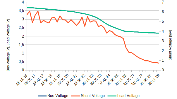
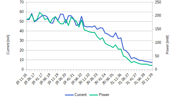
From the charts you see that the bus and also the load voltage are nearly the same because of the small shunt resistor. The load voltage is the voltage of the battery and is around 3.7V when the battery is fully loaded. This is also the nominal voltage of the battery but I think that the battery was not completely full, because the voltage of the battery at 100% state of charge should be around 4.25V.
When the fan stops moving, the load and bus voltage was around 2.1V and after 4 hours of time.
Because of the small shunt resistor, the shunt voltage is very small around 6mV at the start of the experiment and less than 1mV when the experiment finishes.
During the start, the fan consumed around 200mW peak but over time the fan moves slower and the current and power consumption reduces to 9mA and 20mW.
So you see from this tutorial that measuring current and voltage with the INA219 in combination with an Arduino, ESP8266 or ESP32 it not complicated.
If you have any questions to this article, please use the comment section below to ask your questions. I will answer them as quick as possible.
Good Night, I’m using esp32, supply voltage of 12v expected current of maximum 1A, the voltage reading is correct but the current varies a lot, positive and negative random values, what can I do?
I have same problem.
Hi
Its a nice tutorial but I believe the wiring diagram may cause your problems.
The battery positive connects to ground, this doesn’t not make sense.
The wiring in the photograph at the top should work if you can look closely at it.
It is advised to put INA219 between power supply + and device.
Jamie