How to reduce the ESP8266 power consumption?
With the different power saving modes, you can reduce the power consumption of your ESP8266 by 64%.
If you plan to use a battery as power supply for your next project, read the following article that explains the different power modes, modem-sleep, light-sleep and deep-sleep for the ESP8266.
You learn how to use each power mode and how much power you can save.
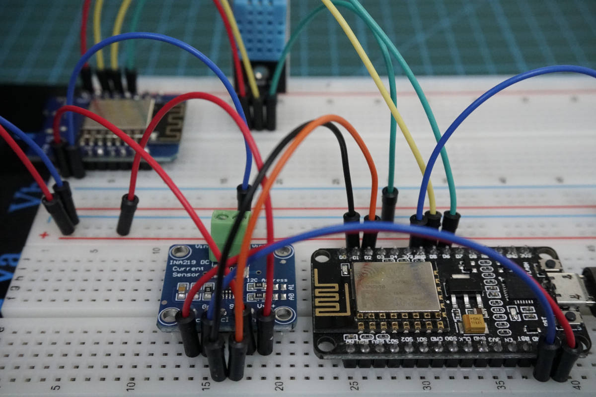
Table of Contents
Why are the ESP8266 power consumption important?
The ESP8266 power consumption is between 15µA and 400mA depending on different use cases.
In idle state with powered WiFi the NodeMCU V2 has a current consumption around 70mA. With an operating voltage of 3.3V a NodeMCU V2 needs the following power in idle state:
W = U * I = 3.3V * 70mA = 231mW
Therefore the energy consumption per year for a NodeMCU is: E = W * 365 * 24 = 2.024 kWh
I live in Germany, where the costs per kWh are around USD 0.34. If I want to build a weather station with one NodeMCU I have electricity costs of more than USD 0.7 per year, which is nearly nothing. So why is the power consumption relevant, when the costs are below USD 1 per year?
If you want to build an outdoor weather station and operate the whole system with a battery, than you have to worry about the power consumption. If you buy a Lithium battery with 1000mAh (Operation voltage: 3.7V), how long will it take until you have to change the battery pack?
T = 1000mAh / 70mA = 14.3h
So you have to change the battery every day. That does not make sense. Moreover it is only the theory that you can use the whole energy of the battery. There are three major influences that will reduce the theoretical lifetime of your system.
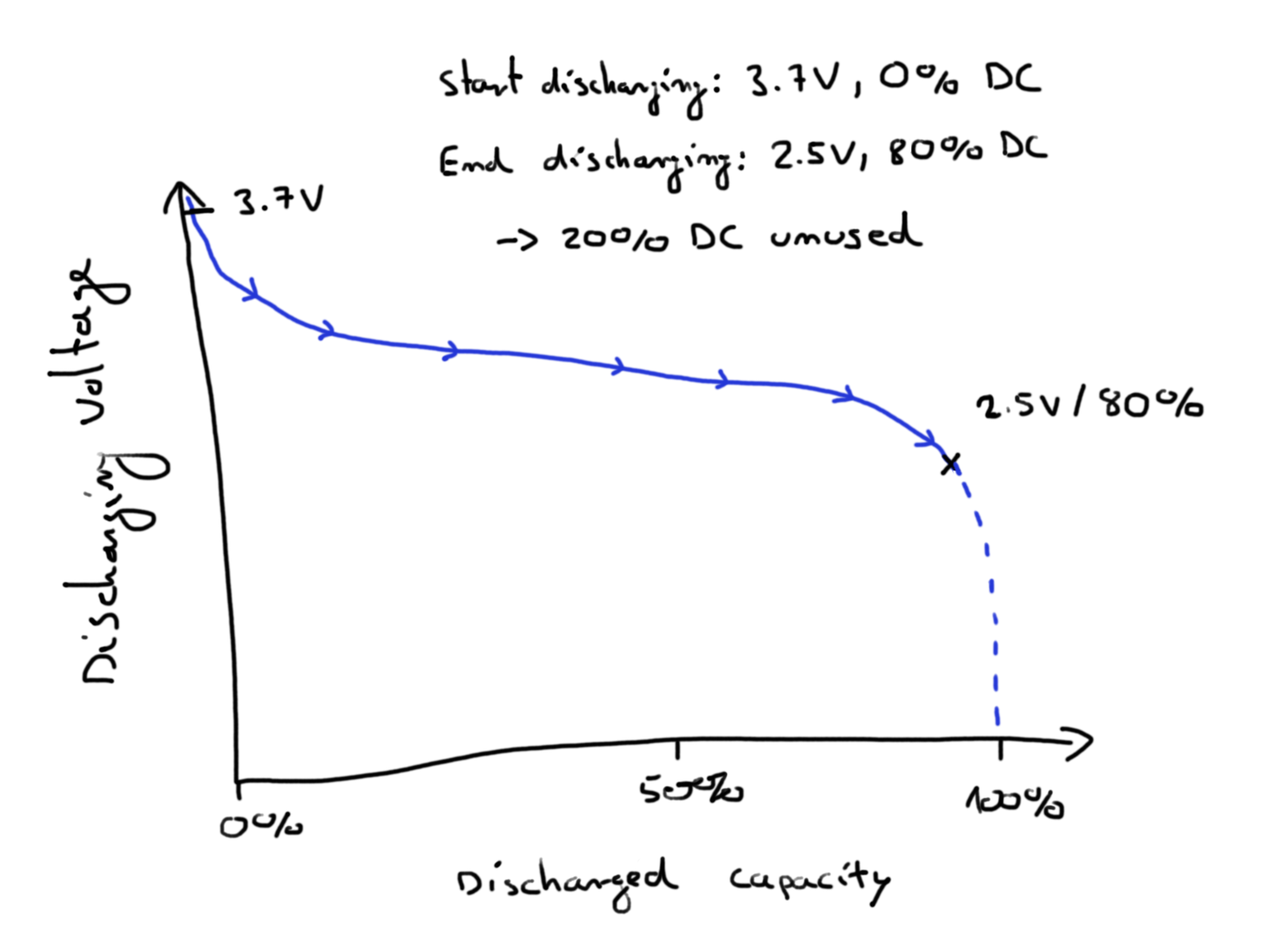
- The ESP8266 need a minimum supply voltage of 2.5V
During the discharge the supply voltage of the battery will drop from 3.7V to 0V. If the supply voltage drop below 2.5V, the ESP8266 will shut down and not turn on again. You have to recharge the battery. Therefore if the technical specifications your battery are 1000mAh you will never use the full 1000mAh.
The following picture shows the discharging curve of a battery. Depending on the battery at first we see a step voltage drop followed by a nearly steady trend of the voltage. If around 70% to 80% of the capacity is used, the voltage drops significant and will fall under the operation voltage of the ESP8266.
- The system will not always stay in idle mode. You will have to run a task once in a while, maybe where the board has to send data to a server. Therefore there will be short time intervals, where the power consumption will be high.
- Every battery has a calendric aging based on the cell chemicals and the temperatures around the battery which reduces the usable capacity of the battery over time.
Options to extend the time between charging the battery
You have two options to extend the time to charge the battery pack.
- Buy a battery with a higher capacity.
- Reduce the power consumption of the ESP8266 microcontroller.
1) Let us assume you buy a battery with 6000 mAh instead of 1000 mAh. I bought such a battery for my own outdoor weather station. You will extend the lifetime of the system by a factor of 6. So you will have to change the battery every 89 hours which results in 3.6 days. I think we both agree that the problem of the external power supply is not solved. We have to reduce the power consumption of the ESP8266.
2) Lets dive deeper into the ESP8266 power consumption. The ESP8266 has several sleeping modes and power solutions related to these modes. In total there are three different sleep modes. The source of the following table is the manual of the producer of the ESP8266 Espressif.
RTC: Real-Time Clock
DTIM: Delivery Traffic Indication Message
| Modem-sleep | Light-sleep | Deep-sleep |
Wi-Fi | OFF | OFF | OFF |
System clock | ON | OFF | OFF |
RTC | ON | ON | ON |
CPU | ON | Pending | OFF |
Substrate current | 15 mA | 0.4 mA | 20 µA |
Average current DTIM = 1 | 16.2 mA | 1.8 mA | |
Average current DTIM = 2 | 15.4 mA | 0.9 mA | |
Average current DTIM = 3 | 15.2 mA | 0.55 mA |
Remember that these are values directly from the datasheet and we do not know under which conditions these low values are measured. Therefore I created my own experiment to compare the different power saving modes. The NodeMCU was powered with a constant voltage of 9V and the WeMos D1 Mini on 6.5V. The absolute values are aggregated and therefore have no real unit. Based on these aggregated values, the reduction of power consumption in percent is calculated.
If you do not want to go in detail, the following table shows the overall results for the ESP8266 NodeMCU and WeMos D1 Mini.
ESP8266 NodeMCU | ESP8266 WeMos D1 Mini | |
Reference | 39.58 | 37.81 |
Modem-sleep | 35.61 (-10.02%) | 27.10 (-28.32%) |
Deep-sleep | 22.03 (-44.34%) | 13.69 (-63.80%) |
The following article explains in detail the different power saving modes as well as how the experiment was implemented and executed.
Experiment to measure the influence of Power Modes
The following table gives you an overview of all components and parts that I used for this tutorial. I get commissions for purchases made through links in this table.
| ESP8266 NodeMCU | Amazon | Banggood | AliExpress | |
| AND | ESP8266 WeMos D1 Mini | Amazon | Banggood | AliExpress |
In this tutorial I want also measure the current consumption that can be saved using different power modes. Therefore I created two experiments:
- Measure the detailed current consumption of one iteration in the an example program to get an indication what are the steps in the program code that causes high current draw.
- Measure the average current consumption of multiple iterations of the example to reduce the influence of outliers in the measurement.
For this experiment I want not only know the influence of the different power modes, but also the difference in the power consumption between the ESP8266 NodeMCU and the ESP8266 WeMos D1 Mini. Therefore I did every measurement for both microcontrollers.
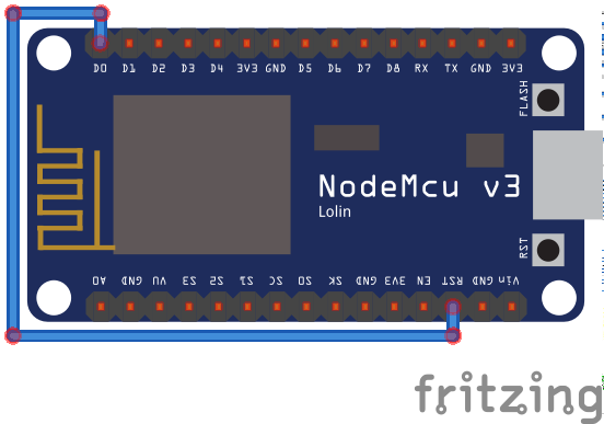
The following picture shows the wiring for the NodeMCU and the WeMos D1 Mini.
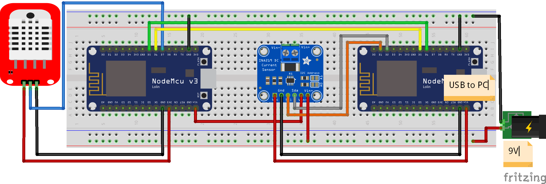
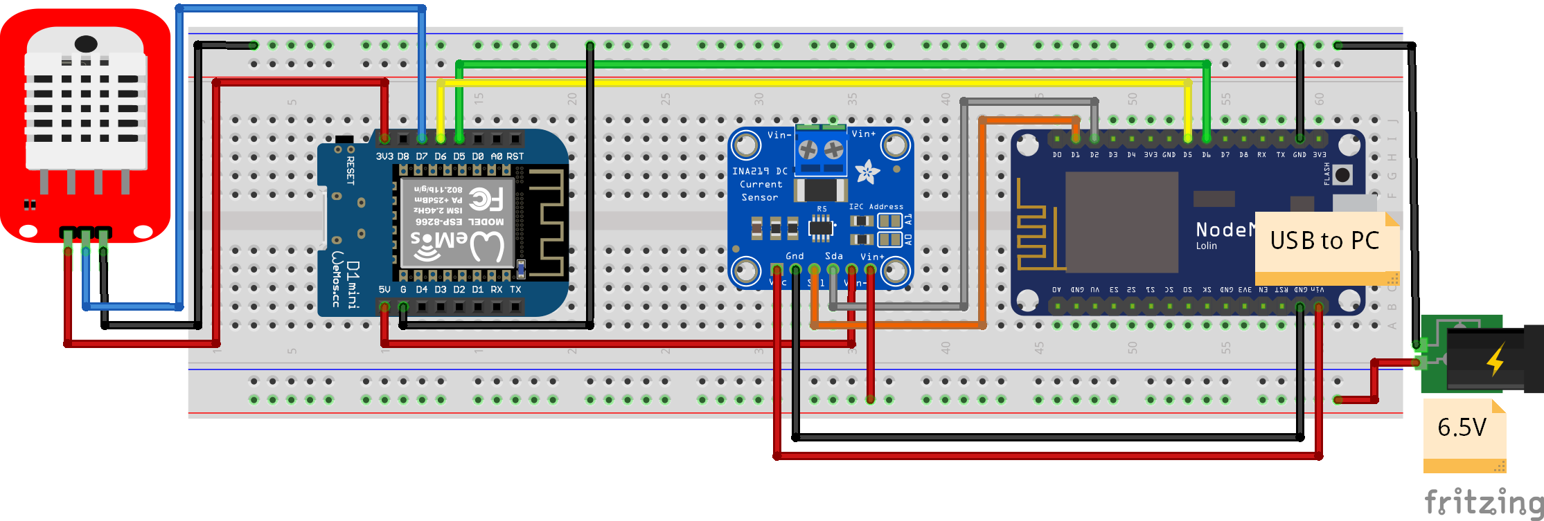
On the left part of the fritzing picture you see the wiring between the tested microcontroller and the DHT22 temperature and humidity sensor module. The microcontroller is connected via UART communication with a NodeMCU that is connected via USB to the PC to record the measurements and to get a stable power, independent of the tested circuit.
To measure the current consumption, I use the INA219 current and voltage sensor, that I describe in detail in the INA219 tutorial. The ESP8266 NodeMCU on the right side of the picture is connected to the INA219 via I2C. The INA219 is connected in series to the tested microcontroller and an external power supply that is adjusted to 9V for the ESP8266 NodeMCU and to 6.5V for the ESP8266 WeMos D1 Mini.
ESP8266 Power Modes Arduino Scripts
You can download all scripts at the end of this tutorial with the download button. The following table shows all the scripts, that are in the download folder and also how to combine the two scripts you need for each experiment.
Measuring the current consumption of the ESP8266 NodeMCU or WeMos D1 Mini over multiple cycles | Measuring the current consumption of the ESP8266 NodeMCU or WeMos D1 Mini over one cycle in detail | ||
ESP8266 NodeMCU to measure the current consumption | Measure_Current_Average | Measure_Current_Detail | |
OR | Reference experiment | Consumer_Reference | Consumer_Reference_Details |
OR | Influence of modem-sleep | Consumer_Modem_Sleep | Consumer_Modem_Sleep_Detail |
OR | Influence of deep-sleep | Consumer_Deep_Sleep | Consumer_Deep_Sleep_Detail |
The first script you need is the measurement script for the NodeMCU. This script is either the Measure_Current_Average program if you want to measure the average current consumption over multiple cycles of the experiment or Measure_Current_Detail to only measure on cycle of the experiment but therefore in detail.
This measurement script is then combined with only one of the three following script for either the NodeMCU or the WeMos D1 Mini.
- Reference experiment with no use the power modes.
- Influence of modem-sleep to use the modem-sleep power mode.
- Influence of deep-sleep to measure the current consumption in the deep-sleep mode.
For the program example I use a script that measures the temperature and humidity of a DHT22 sensor every 10 seconds and send the measurement via MQTT to a Raspberry Pi. If you are interested in the example script, I wrote a whole tutorial for this MQTT example. Of cause you can use any other script to compare the influence of the power modes on the current consumption.
Reference Measurement for the ESP8266
The first measurement is without any use of a power mode and therefore the reference of the following measurements. The following picture shows one cycle of the reference measurement. The y-axis of all pictures do not have a unit because it is scaled multiple times and therefore a unit does not make any sense. But to compare the influence of the different power modes, no unit is needed.
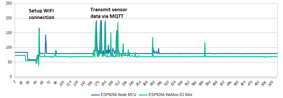
You see that overall the WeMos D1 Mini has a lower current draw over one cycle because in idle state there is a gap between the NodeMCU and the WeMos. There are also two different times in one cycle of the program where the current consumption peaks. The first time is when the microcontroller sets up the WiFi connection to the Raspberry Pi. After the connection is established, the microcontroller reads the sensor values, where no high current is needed. When the temperature and humidity is sent via MQTT to the Raspberry Pi however the power consumption rises for a second time.
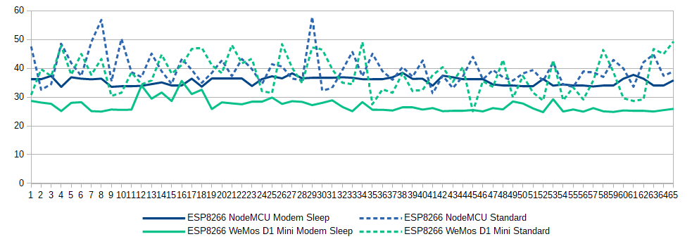
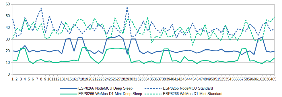
After the detailed view of one cycle, the following picture shows the behavior of the current over 65 cycles. Each measurement is the sum of the current of one cycle.
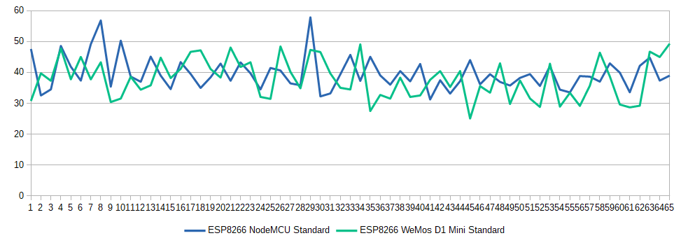
The current demand for both microcontrollers is between 30 and 50 with some outliers. From the picture we see, that in most cases the current consumption of the NodeMCU is higher compared to the WeMos D1 Mini. But it is also possible that the WeMos has a higher power consumption. Therefore I calculated the average current per cycle for both microcontrollers with the following result:
- Average current consumption of NodeMCU: 39.58
- Average current consumption of WeMos D1 Mini: 37.81
After we set our baseline, we go into the different power saving modes of the ESP8266. For the modem-sleep and deep-sleep, I calculated the detailed and average power consumption to compare the different results.
Modem-sleep
The modem-sleep mode is automatically accessed by the ESP8266. Also the wake up trigger is automatically set. Therefore you do not have to configure an interface.
If you want to set the NodeMCU to Modem-sleep you have to set up the WiFi connection via STA mode (station mode). STA mode is used to get the ESP8266 connected to a WiFi network established by an access point like a router.
#include "ESP8266WiFi.h"
#include "WiFiClient.h"

void setup() {
  Serial.begin(115200);

}

void loop() {
  WiFi.mode( WIFI_OFF );
  WiFi.forceSleepBegin();
  Serial.println("WiFi is down");
  delay(20000);

  WiFi.forceSleepWake();
  delay(1);
  // Bring up the WiFi connection
  WiFi.mode(WIFI_STA);
  WiFi.begin("XXX", "XXX");

  // Wait until the connection has been confirmed before continuing
  while (WiFi.status() != WL_CONNECTED) {
    delay(500);
    Serial.print(".");
  }

  // Debugging - Output the IP Address of the ESP8266
  Serial.println("WiFi connected");
  Serial.print("IP address: ");
  Serial.println(WiFi.localIP());
  delay(2000);
}
In Modem-sleep mode, the ESP8266 stays connected to the current Wi-Fi through the DTIM beacon mechanism.
The DTIM beacon mechanism
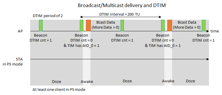
Beacons are broadcast transmissions sent by the master of the network. A beacon transmission is periodic and is normally set in multiples of Transmission Units (TU). Beacon transmission terminology is DTIM (Delivery Traffic Indication Map) interval. This interval is a multiple of the basic beacon transmission interval.
For example: If the basic beacon transmission interval is 100ms and the DTIM interval is 2, then every second beacon is a DTIM beacon. Each beacon has a down counter (Beacon DTIM cnt) in each beacon transmission. While the counter is counting to zero the ESp8266 is in Modem-sleep mode. If the counter has a value of 0, it is the DTIM beacon and the ESP8266 wakes up the WiFi to receive data.
The DTIM interval could also be greater than 2. The greater the DTIM interval is, the longer the ESO8266 stays in the Modem-sleep mode and saves energy.
Modem-sleep Current Measurement
After we know how the modem-sleep power function works, we want to know how the power saving mode influences the current consumption in the experiment. The following picture shows the details of one cycle in the MQTT experiment.
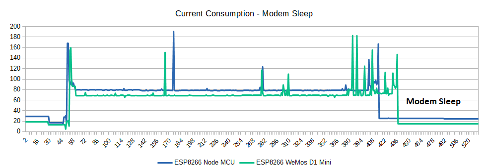
Compared to the reference measurement we see that there are also current spikes up to nearly 200, because the modem sleep function can not have an influence to the power consumption that is needed to connect the microcontroller to the WiFi network or to transfer the sensor data via MQTT to the Raspberry Pi.
But what we see is, that when the data is sent, the WiFi of the microcontroller is shut down and therefore the current consumption is reduced from 75 in the reference measurement to 25.
That the overall power consumption is reduced is also clearly visible in the next picture, that shows the measurement of multiple cycles for the modem-sleep function compared to the reference measurement.
If we compare the current consumption of the ESP8266 NodeMCU to the WeMos D1 Mini, we see that the WeMos consumes less energy in modem-sleep mode with on average 27.10 to 35.61 for the NodeMCU. Therefore if we want to maximize the lifetime of a battery powered experiment, we see a positive influence using the modem sleep mode.
Light-sleep
The light-sleep mode is quite similar to the Modem-sleep mode. The only two differences are:
- ESP8266 powers of the system clock
- The internal CPU is suspending
Therefore the board will not respond to signals and interrupts from other hardware interfaces. The ESP8266 need to wake up from an external GPIO. The wake up process needs less than 3ms. The interface to wake up the ESP8266 by GPIO is: void gpio_pin_wakeup_enable(uint32 i, GPIO_INT_TYPE intr_state);- uint32 i: The IO serial number of the wake-up function.
- GPIO_INT_TYPE intr_state: The trigger mode of wake-up: GPIO_PIN_INTR_LOLEVEL or GPIO_PIN_INTR_HILEVEL
These two differences results in a big drop in consumption from 15mA to 0.4mA.
The following example will connect and deconnect the NodeMCU to the local WiFi and set the sleeping mode to light sleep.
void setup() {
  Serial.begin(115200);
}

void loop() {
  // Disable light sleep
  wifi_set_sleep_type(NONE_SLEEP_T);
  delay(2000);

  // Enable light sleep
  wifi_set_sleep_type(LIGHT_SLEEP_T);
  delay(2000);
}
Deep-sleep
f you want to use an external power supply and save the most energy possible, go with the deep-sleep mode! The ESP8266 power consumption reduces in theory to 20µA * 3.3V = 66µW. Your external battery with 1000mAh will last a lot longer.
T = 1000mAh / 20µA = 50,000h = 2083 days = 5.7 years (note that this lifetime cannot be used due to the three major influences that will reduce the theoretical lifetime of your system)
Unlike the other two modes, the system cannot go into Deep-sleep automatically. Users can call the interface function system_deep_sleep to immediately enable Deep-sleep. In this mode, the chip will turn off Wi-Fi connectivity and data connection; only the RTC module is still working, responsible for periodic wake-ups.
To enable the deep-sleep mode you only have to use the following line of code: ESP.deepSleep(uint32 time_in_us); where you define a time, when the ESP8266 will wake up from the deep-sleep mode. The maximum time in deep-sleep is 4,294,967,295 µs, which is about ~71 minutes.
After the defined time, the ESP8266 will be wake up by a reset pulse from the D0 pin (GPIO16), which is defined as the wake-up line. Therefore you have to physically connect D0 with RST.
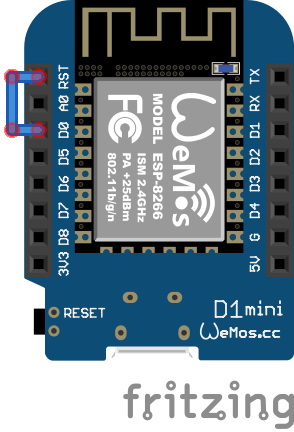
The following two pictures show how to connect the D0 pin with RST to wake up the ESP8266 NodeMCU and WeMos D1 Mini microcontroller after the deep sleep phase..
Deep-sleep Current Measurement
Because in theory the deep-sleep mode of the ESP8266 is the mode, where the microcontroller has the lowest power consumption, we want to know how low is the consumption compared to the reference example.
The following picture shows again one cycle of the experiment in detail. Like in the modem-sleep mode, the power consumption, when the microcontroller sets up the WiFi connection and sends the measurements, is not reduced but when the ESP8266 goes into the deep-sleep mode, the current consumption drops to even lower values compared to the modem-sleep more.
When we compare multiple runs of the experiment we see the same result.
How much reduces deep sleep the current consumption?
The deep-sleep mode reduces the current consumption of the ESP8266 by 44% for the NodeMCU and by 64% for the WeMos D1 Mini compared to the use of no power mode. Therefore if you have a project that depends on the lifetime of a battery, the usage of the deep-sleep mode is essential.
Important is, that in the experiment the microcontroller goes into the sleep mode only for 10 seconds and then continues the loop function with the next cycle. In a real word project, for example an outdoor weather station, the sleep time would be several minutes and not seconds. Therefore the influence of the deep-sleep mode would be even larger, resulting in a far lower current draw.
The second important fact from the picture above is that again the WeMos consumes almost half the power in the deep sleep mode compared to the NodeMCU. In my opinion it is clear that the WeMos consumes less power because the whole microcontroller is smaller with fewer parts that need energy.
Conclusion
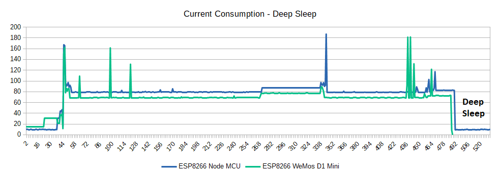
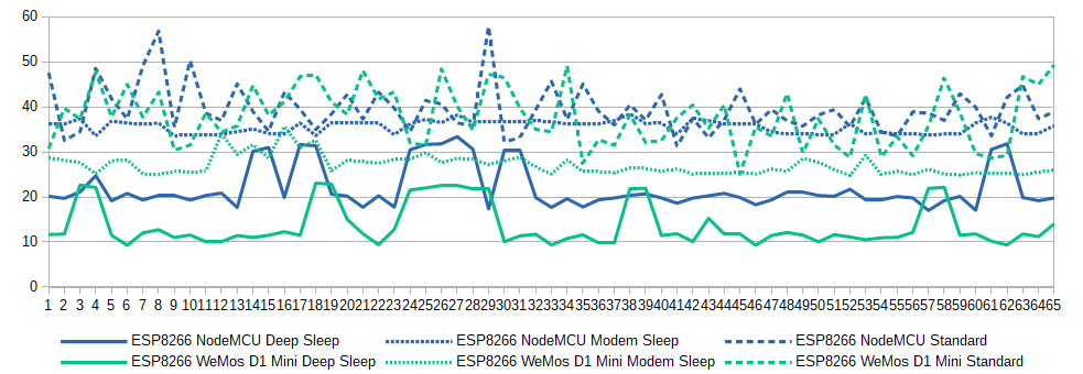
In this article you learned how you can extend the lifetime of your battery powered project with the deep-sleep mode. If you plan do make a project that is battery powered, I would recommend a WeMos D1 Mini in combination with the deep sleep power saving mode. The following picture shows the current consumption of multiple cycles for all tested power modes and the reference measurement.
With the following button you can download the Arduino scripts that I use for the different experiments. When you click on the button, you download all files in a zip folder.
I hope you enjoyed the reading and will use the deep sleep mode in your current or next project. Do you ever used an external power supply for one of your project? What is your next project and will you use the deep sleep mode? Let me know and write in the comments.
Also if you have any questions regarding the power saving modes, use the comment section below to ask your question. I will answer them as soon as possible.
Thank you
Hi Tom,
your are Welcome.
Thanks for excellent explanation,
However I’m not quite understanding on the way you present the unitless data. Could you elaborate more? on what’s your method and what’s actually the number representing. Also is the 2nd table unitless too? I’m looking for a benchmark result on that 2 dev board.
On unrelated topic, I’m from Indonesia and btw I can’t access your website directly. It’s shows on google search result but I need to use VPN to open it 😀
Hi Adam,
I just bought me a new multi-meter with USB connection where I can measure the current consumption more easily. I will update the article as soon as possible.
This is amazing. Thanks!
Great article! Just to make sure I understand the power consumption correctly, during deep sleep the NodeMCU version can only drop down to 10 mA (which what I I have experienced), but the WeMos D1 can go below 1 mA to, as per specs, 10 uA?
I cannot work a weather station (a refrigerator sensor actually) with 10mA consumption. That runs my batteries down very quickly.
HGello,
to reach very low current with deep sleep, you must use a ESP8266 ALONE, that is to say a ESP-01or ESP-01S; I did measurements in deep sleep for the 2 devices:
8 mA for Wemos D1 with 3V3 supply
19 µA (19 micro Amp) for a ESP-01S with 3V3 supply
The explanation is that on a Wemos D1 some additional components remain supplied (like the USB interface, voltage regulator …)
Aristotle – hi, yours is a question that interested me greatly because I have been trying to make a fridge temperature sensor using an ESP32 with BLE signalling to an external device which controls the fridge pump. I had no idea the current drain was as high as it did until I started doing some measurements – and reading this excellent article. I’ll start looking at alternative controllers now.
Hi Tom,
Thanks for creating this article. I’ve several ESP8266 sensors continuous up and running to measure operating duration on different 18650 battery capacities. After a couple of years of investigation, the operating duration on 2000mAh..3000mAh batteries with my NodeMCU v3 and WeMos D1 mini boards is extremely low: In the range of a few weeks and not months or years. Let me explain why:
I measured the following continuous power consumption in deep sleep with external 3V3 power connected:
– WeMos D1 ESP12F CH340 pin 3V3 = 6.4mA @3.3V
– NodeMCU v3 CP2102 pin 3V3 = 9.0mA @3.3V
This even worse when connecting >=4.2V power externally via the on-board LDO:
– WeMos D1 ESP12F CH340 pin 5V = 8.6mA @4.2V
– NodeMCU v3 CP2102 pin VIN = 9.0mA @4.2V
You can see continues power consumption as well in your graph “Current Consumption – Deep Sleep” section “Deep Sleep” for the “ESP8266 Node MCU”. However, I never see 0mA for the “ESP8266 WeMos D1 Mini” which looks like impossible for this board.
Reasons for continuous power consumption can be mentioned in your article:
1. The on-board serial interface chip is not set in power-down.
2. High quiescent current of the cheap on-board 3.3V LDO voltage regulator.
3. The higher the input voltage, the higher the power consumption of the LDO.
Another essential point is missing: After trying several DHT22 sensors from different manufactures, the operating voltage of the DHT22 sensor is also limited to around 3.3V. Read errors occurs randomly after hours when the (battery) voltage decreases, so the battery needs to reached much earlier. This random behavior makes it difficult to calculate the expected battery lifetime.
If you want to run sensor devices with the ESP8266 battery powered, then there are much better alternatives:
1. Use a ESP8266 bare board without regulator and no serial interface chip.
2. Use a 3.3V low quiescent voltage regulator like HT7333.
3. Use a different temp/hum sensor with wide operating voltage range. (For example BME280 which works reliable at 2.0V and set the sensor in sleep mode when not used)
4. Low quiescent current 18650 battery protection circuit such as TP4056.
With this setup, my current consumption in deep sleep decreases to around <750uA. The range of 20 uA in deep sleep is not feasible, because other external components are also needed.
You can also mention the ESP.deepSleep(time, WAKE_RF_DISABLED);. In this case the CPU resets with WiFi disabled. (~20mA vs 80mA) It is also possible to store the sensor data in EEPROM or SPIFS flash to reduce the number of WiFi connections like once in an hour.
Maybe you can use this information. Yes, low-power hardware and software design is a difficult topic to find the right information on internet.
Thanks,
Erwin
I can 100% confirm the findings from Erwin above. My garden powered devices uses HT7333 and a naked ESP8266 and run nearly forever. I developed the deepsleep option for TASMOTA firmware. This has the option to define longer deepsleep times like 71minutes and also has a time correction module to compensate time drift during deesleep based on temperature.
I have a program to open & close my drapes.
to run it i need to turn it on then run it then turn off or battery runs down too quick.
I got all your zip files but don,t need all the things in them.
I see this:::::: ESP.deepSleep(10e6); at end of programs is this all i need to add to mine
I want it to run 24/7 and if it is asleep when i want to run it how do i start it up?
Thanks for the detailed analysis.
I’m currently not yet sure which way to go in terms of hardware.
So for the development of the SW I will stay with the Wemos D1 mini and the battery shield I have.
I use an MQTT broker and node-red for data collection.
My normal sensors are the Sonoff TH and POW devices, so there is no need to worry about the power.
But for other projects I want to have battery powered devices.
Currently I’m planning to use static IP instead of DHCP and UDP instead of MQTT/TCP to reduce the high power time. It would be interesting for me if you did try this in your setup and compare the measurements. (That way you will do the work of validating my assumption that static-IP/UDP is better than DHCP/TCP/MQTT. 😉 )
Kind regards,
Urs.