Rain Sensor Tutorial for Arduino, ESP8266 and ESP32
In this tutorial, you learn how the different parts of the rain sensor module are working and how to connect the rain sensor module to your Arduino, ESP8266 or ESP32 microcontroller board.
If you want to use the rain sensor for a long time, you learn in the last example how to increase the lifetime of the sensor.
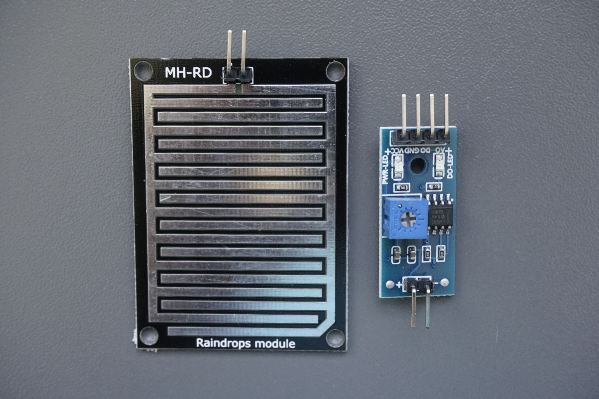
Table of Contents
What is a Rain Sensor for Microconrollers?
Rain Sensors also called raindrop sensors are very handy sensors that are used in a variety of use cases. Alone a rain sensor can only detect if it is raining and how strong it rains but in combination with other electrical devices you can build useful applications.
For me the most useful application is to detect an open window when it starts to rain because I am often not sure if I closed a window after I left the house.
The rain sensor consists of 2 components, which we consider in more detail below:
- Rain drop module to detect if it is raining or not
- Control board to process the data from the rain drop module
Functionality of the Rain Drop Module
The rain drop module is a printed circuit board in a rectangular shape. The size can differ between models but the construction is the same for each model. The ground plate of the circuit board consists of fiber reinforced plastic that is not conductive. On top of this ground plate there are two pins mounted. From each of these pins starts one conductor track, build like an “E” with an offset against the other conductor track. Therefore the tracks are not connected but the conductor tracks are close together.

You can measure the resistance of the rain board with a multi-meter, like I did. The following two pictures show the rain board in dry condition with an infinite resistance and after I put my finger on the board with a resistance of 3.87 MΩ.


Why does Resistance Change on a Rain Drop Module?
The schematic illustration shows the difference between a variety of states for the rain board. With no rain there is no connection between the two copper tracks and the resistance is infinite.
During light rain there are some water drops that land on the surface of the rain board and connect the two conductor tracks. Because water is conductive, the resistance of the rain board decreases resulting in a medium resistance. The same happened when I touched the rain sensor, because my skin is also conductive, connecting both copper tracks.
If there is heavy rain, more and more rain drops falling on the board and further decrease the resistance until the resistance is 0Ω and the circuit is shorted.
Summarizing the rain board: The rain board is a rain depended resistor that has a high resistance when there is no rain and a low resistance when rain drops are on the circuit board. The operating principle is the same as that of a photoresistor.
Now we have to make sure that we can measure the change of the resistance. If your read my resistor tutorial, you know that this can be done with a voltage divider.
Functionality of a Voltage Divider
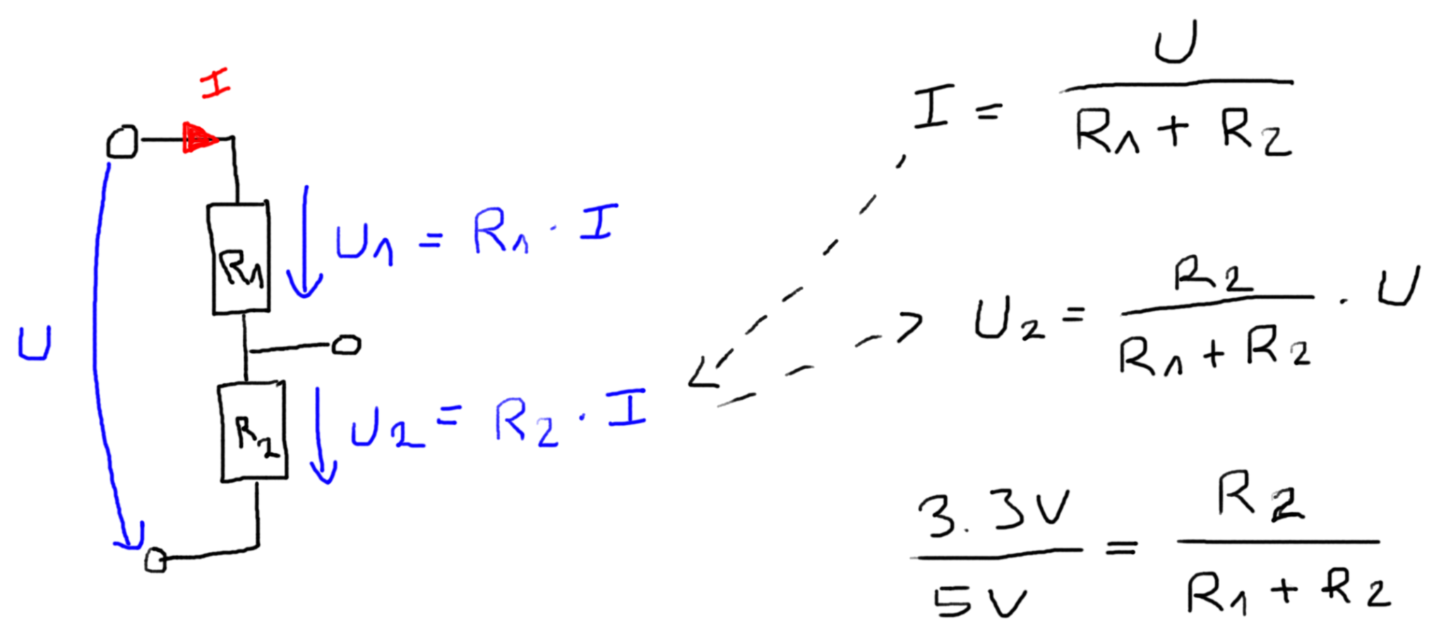
The following picture shows a voltage divider consisting of two resistors. In our case R2 is the resistor of the rain board. R1 is a reference resistor with a known resistance. From the equation you see that if we know the supply voltage U, we can calculate the voltage drop over the rain board.
But where do we find the voltage divider? This function has among other things the control board.
Functionality of the Control Board of a Rain Sensor
The control board consists of two input pins and four output pins. The input pins are connected to the rain board and the output pins to your favorite microcontroller, for example an Arduino Uno or an ESP32 NodeMCU.
On the control board you find multiple resistors that also functions are the voltage divider to provide an analog signal for the rain intensity. Therefore as input we get a resistance from the rain board and the control board converts this resistance into a voltage drop between the analog pin and ground. The microcontroller uses the internal analog to digital converter (ADC) to convert the voltage from the analog pin to a digital value between 0 and 1023 that can be printed to the serial output in your Arduino IDE.
The biggest part on the control board is the potentiometer to adjust the sensitivity of the rain detector. The potentiometer is only a variable resistor whose resistance is changed with the setting wheel at the top. We need this potentiometer to compare the resistance of the potentiometer with the resistance of the rain board. If the resistance of the rain board is lower than the threshold, defined by the potentiometer, the digital output of the control board changes from 1 HIGH to 0 LOW.


But who does this comparison between the two resistances? This is done by the LM393 comparator because the voltage drop over both resistors is linear to their resistance due to ohms law. The LM393 consists of two independent precision voltage comparators and is specially designed to operate from a single power supply, in our case the microcontroller. You find more details about the LM393 on the website of Texas Instruments.
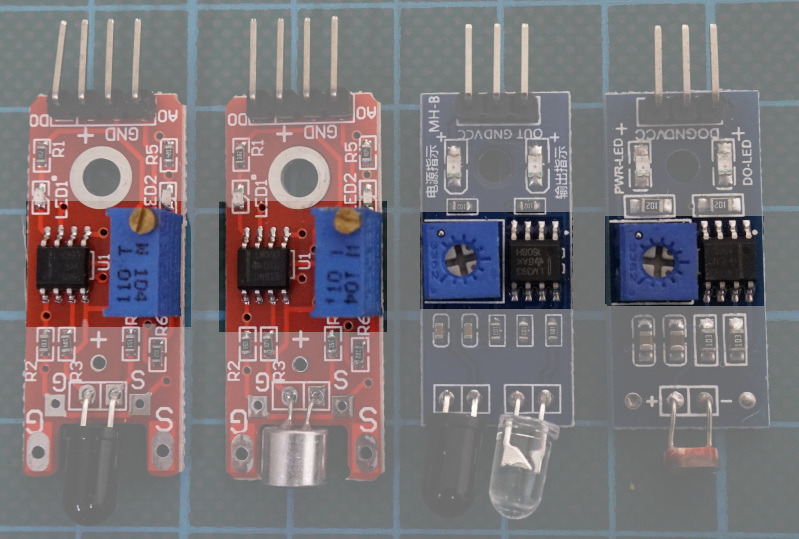
From the following picture you see that the combination of a potentiometer and the LM393 comparator is very often used for different kinds of sensors where you have to convert an analog signal to a digital signal via the threshold of the potentiometer.
The control board has also a build in LEDs that indicates the power status of the board and the status of the threshold. If the digital output of the control board changes from HIGH to LOW, indicating that it is raining, the status LED of the control board turns on.

Microcontroller Datasheet eBook
The 35 pages Microcontroller Datasheet Playbook contains the most useful information of 14 Arduino, ESP8266 and ESP32 microcontroller boards.
Wiring between Rain Sensor and Arduino Boards
The following pictures show the wiring between the rain drop module and the control board as well as the connection between the control board and different Arduino boards. Because the rain board only connects a resistance to the control board, switching the connection pins does not have any influence.
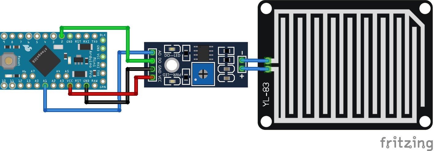
The control board is powered from the 5V pin of the Arduino microcontroller board. For the analog and digital connection, you can use any digital I/O and analog pin on your board, but if the connection differs from the one in the pictures, make sure that you define the correct pins in the following sections with the program code.
If you are missing an Arduino microcontroller board, please write a comment in the section below this article and I will add more fritzing pictures of the wiring of the rain sensor. You can also enlarge the wiring pictures by clicking on them.

For more information about the Arduino Nano, visit the Arduino Nano Tutorial.
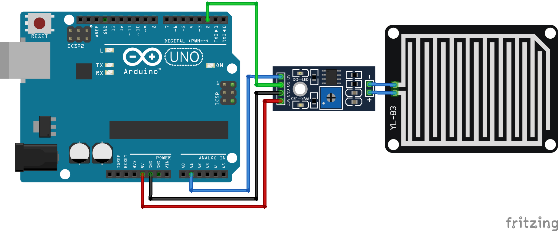
For more information about the Arduino Uno, visit the Arduino Uno Tutorial.
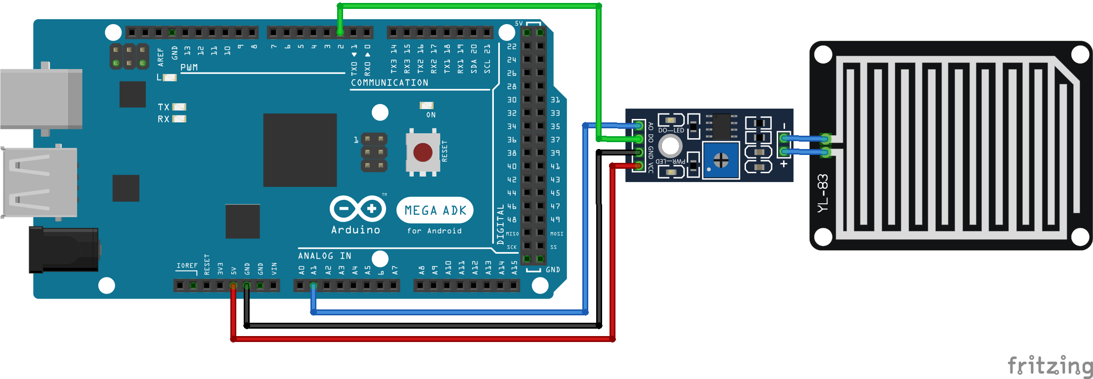
For more information about the Arduino Mega, visit the Arduino Mega Tutorial.
Wiring between Rain Sensor and ESP8266 Boards
The wiring between different ESP8266 boards and the rain sensor module is shown in the following pictures. For the power supply, I take the VIN and 5V pin from the USB converter, but you can also use the 3.3V pin instead because the control board operates also with a voltage of 3.3V.
The connection between the rain drop module and the control board can be switched in polarity without influencing the functionality, because the rain drop module is nothing else than a resistor for the whole circuit.
If you are missing an ESP8266 microcontroller board, please write a comment in the section below and I will add more fritzing pictures of the wiring of the rain sensor. You can also enlarge the wiring pictures by clicking on them.
Wiring between Rain Sensor and ESP32 Boards
The wiring between the rain sensor and the ESP32 microcontroller board is shown in the following picture. Because the ESP32 has multiple analog to digital converter, you can choose several pins for the analog and digital input of the ESP32. I recommend to download my Microcontroller Datasheet eBook with detailed pinouts that shows every analog and digital pin of multiple Arduino, ESP8266 and ESP32 microcontroller boards.
You can switch the connection between the rain drop module and the control board without influencing the functionality, because the rain drop module behaves like a resistor for the whole circuit.
If you are missing an ESP32 microcontroller board, please write a comment in the section below and I will add more fritzing pictures of the wiring of the rain sensor. You can also enlarge the wiring pictures by clicking on them.
The following table gives you an overview of all components and parts that I used for this tutorial. I get commissions for purchases made through links in this table.
| Component | Amazon Link | AliExpress Link |
|---|---|---|
| Arduino Nano | Amazon | AliExpress |
| Arduino Pro Mini | Amazon | AliExpress |
| Arduino Uno | Amazon | AliExpress |
| Arduino Mega | Amazon | AliExpress |
| ESP32 ESP-WROOM-32 | Amazon | AliExpress |
| ESP8266 NodeMCU | Amazon | AliExpress |
| ESP8266 WeMos D1 Mini | Amazon | AliExpress |
| Rain Sensor (in Sensor Kit) | Amazon | AliExpress |
Read the Analog and Digital Output of the Rain Sensor Module
In this example we can use the wiring from the previous chapter and want to print the analog and digital sensor values to the serial monitor. Additionally we use the serial plotter of the Arduino IDE to show the time-series chart of the analog output.
The following sections shows the Arduino program code for this example.
// for Arduino Microcontroller
#define rainAnalog A1
#define rainDigital 2

// for ESP8266 Microcontroller
//#define rainAnalog A0
//#define rainDigital D1

// for ESP32 Microcontroller
//#define rainAnalog 35
//#define rainDigital 34

void setup() {
  Serial.begin(9600);
  pinMode(rainDigital,INPUT);
}
void loop() {
  int rainAnalogVal = analogRead(rainAnalog);
  int rainDigitalVal = digitalRead(rainDigital);

  Serial.print(rainAnalogVal);
  Serial.print("\t");
  Serial.println(rainDigitalVal);
  delay(200);
}
The first step of the Arduino script is to define the analog and the digital pins that connect the microcontroller and the control board. In my case I use the pin A1 for the analog connection and D2 for the digital connection of the Arduino microcontroller as you see in the fritzing sketch of the Arduino Uno.
For the ESP8266 NodeMCU and WeMos D1 Mini and also for the ESP32, the definition of the analog and digital pins differ. They are included in the script but commented. If you use an ESP8266 or ESP32 microcontroller uncomment the lines of code and comment the definition of the Arduino pins.
In the setup function I set the baud rate of the serial connection to 9600 that have to match to the serial output setting of the Arduino IDE to print the values. Also I have to set the digital pin as input because I want to read values at these pin.
In the loop function I create the variable rainAnalogVal as integer and read the analog value from the analog pin with the build in function analogRead(). Then I read also the digital value, with the build in function digitalRead() and store the digital value in the variable rainDigitalVal that has the following values:
- = 0, if it is raining
- = 1, if it is not raining
To view the time series chart of the analog rain sensor we print the analog and digital value to the serial output and with a short delay of 200 milliseconds we pause the script at the end before the loop is executed again.
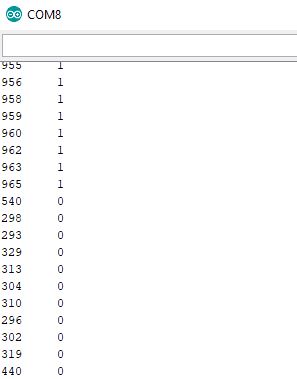
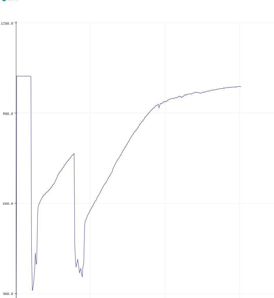
The following two picture show the serial monitor and the serial plotter of the Arduino IDE. You see clearly that the sensor value drops when I touch the rain board with my dry or wet finger. You can click on each image to enlarge it.
Analog and digital output of the rain sensor module, visualized by the serial monitor
Analog output of the rain sensor module, shown as time-series chart with the serial plotter
Bonus: Increase the lifetime of the rain sensor
Due to the current flow and the contact with water, the rain sensor will build rust from electrolysis that damages the sensor and makes the sensor inaccurate. How strong the electrolysis will be depends on three different factors:
- the quality of the rain board,
- the amount of water on the rain board
- how often and how much current is passed through electrodes of the rain board
To increase the lifetime of the rain sensor we reduce the operating voltage from 5V to 3.3V and also only provide voltage to the sensor when we want to read the sensor values with the microcontroller. Therefore we change the wiring and do not longer connect the 5V pin of the Arduino microcontroller or the VIN pin of the ESP8266 and ESP32 based microcontroller to the control board but we connect the microcontroller via the 3.3V pin.
Moreover we do not connect the Arduino, ESP8266 or ESP32 microcontroller direct to the rain sensor, but we use a MOSFET to disconnect the rain sensor completely from the circuit when we do not need to read the analog sensor value. I use the IRLZ44N MOSFET because this logic level MOSFET responds also for low voltages between 2.5V or 5V.
The following picture shows the new wiring with an Arduino Uno as example.
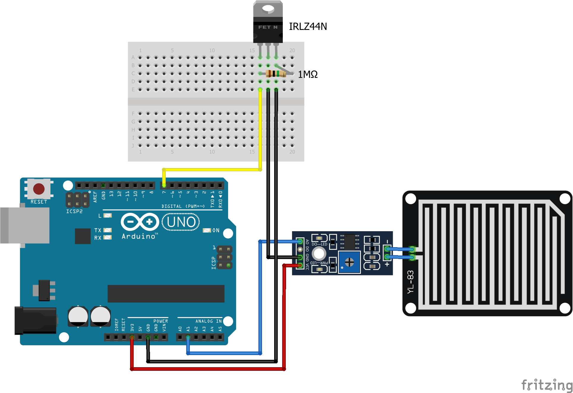
From the fritzing picture you see also that I use an 1MΩ resistor to protect the gate to source from electrostatic discharge.
With this change we reduce the operation voltage to 3.3V and with the digital pin we can control when the digital pin is set HIGH to to turn on the rain sensor and when to set the pin LOW to shut down the sensor.
One downside is that the internal analog to digital converter (ADC) of the microcontroller has 5V as reference voltage and now not the full value range is used for the analog signal. You see the reduced maximum analog value in the last picture of this article.
I also build the digital value based on the analog value in the Arduino script and not by the analog pin of the control board. Therefore I do not have to connect the digital pins.
The following lines show the new script and the changes that we have to make.
#define rainAnalog A1
#define sensorPower 7
boolean bIsRaining;

void setup() {
  Serial.begin(9600);
}
void loop() {
  digitalWrite(sensorPower, HIGH);  // Turn the sensor ON
  delay(10);              // Allow power to settle
  int rainAnalogVal = analogRead(rainAnalog);

  if(rainAnalogVal < 100) {
    bIsRaining = true;
  }
  else {
    bIsRaining = false;
  }
  digitalWrite(sensorPower, LOW);    // Turn the sensor OFF

  Serial.print(rainAnalogVal);
  Serial.print("\t");
  Serial.println(bIsRaining);
  delay(1000ul*60*5); // wait for 5 Minutes
}
The first change we make is to define two new variables:
- sensorPower defines the new digital pin that connects the control board to the microcontroller.
- bisRaining is a boolean value that shows if it is raining or not.
The variable for the digital value is deleted in the define block at the beginning of the script and also in the setup function.
In the loop function we turn on the control board by setting the pin of the sensorPower HIGH and let the power settle before we read the analog value. The boolean value is built by a simple if else function. In my example I choose 100 as the threshold but you can choose a different value if you want. After the analog and digital values are calculated we turn off the rain sensor by setting the power pin LOW.
The following picture shows the output of the Arduino script with a maximum analog value of 131 instead of 1023.

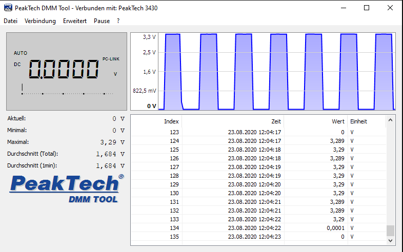
To prove that there is no current low through the rain sensor, when the MOSFET disconnects the rain sensor from the microcontroller, I measured the voltage between both contacts of the rain sensor and changed the Arduino script that there is a 5 second current flow, followed by a disconnected period of 5 seconds. The following picture shows that the voltage of the rain sensor oscillates between 3.3V and 0V. Therefore we know that the MOSFET circuit is working well.
I hope you liked this tutorial and if you have any questions regarding this tutorial leave a comment below and I will answer your questions as soon as possible.



Operating the sensor off a digital pin on an Arduino Uno won’t operate it at 3.3V because the Uno is a 5V logic level device. Also the delay(1000) in the last line of your script only lasts for 1 second, not 5 minutes. The parameter for the delay() function is in milliseconds.
Hi Phil,
you are right regarding the delay and I changed the script. Also I changed the whole concept of the lifetime increase. Now I added a MOSFET to the circuit and changed the voltage to 3.3V. From the voltage measurement you see that now the voltage is between 0V and 3.3V.
Thanks for this useful writeup! I am a complete noob, just barely starting to dabble into the wonderful world of DIY electronics.
I have always wanted a rain sensor. I do not use A/C and have all of my windows open during summertime. I also air-dry my laundry outside. So it is very important for me to notice immediately when it starts to rain. That’s why your article caught my attention.
At the end of the article, you talk about the step you could take to suppress the corrosion of the sensor. Maybe I am just ignorant, but even with this tweak, when you have this sensor exposed to the elements all the time, it will corrode and become useless rather quickly, won’t it?
If you have other methods to make this sensor last for in terms of years, or other types of sensors you could use that are more corrosion resistant, I would love to know!
Thank you very much!
Yasuro
Hi Yasuro,
you are right, over the time, the sensor will corrode and you have to change it. Therefore I would suggest du find a industrial rain sensor that you can buy as replacement part and functions like a reed switch. Therefore it does not need a power supply. With the reed switch you connect a digital pin to the rain sensor and if it is raining, the reed switch pulls the 3.3V to 0V on this line and you see that it rains. If you are more interested in the function of a reed switch, visit my reed switch tutorial.
Hi, your tutorial is very helpful, but I’m wondering, do you have any documentation for this sensor?
Very fine document and explanations. Very thank’s
Hi Frederic,
I am glad that you like the article.
Well explained tutorial, You made my project simpler. Thank You
Hi Alsan,
glad to hear that the tutorial was helpful for your project.
I’m not getting it. I did it exactly like you with the only exception, that I did not use a 1M resistor for the IRLZ44N and I’m using an ESP8266. However the rain sensor always seem to have power, no matter whether I set the IRLZ44N to high or low. I have checked that I do not have any bridges or any connections that shouldn’t be there..