RFID Sensor Tutorial for Arduino, ESP8266 and ESP32
In this tutorial you learn everything you have to know about RFID for your next project with an Arduino, ESP8266 or ESP32 microcontroller.
After we learn the basics of a RFID system, we see how power and data is transferred between the RFID reader and the tag.
After the theory an example of an automated coffee counter shows you the RC522 module in action.
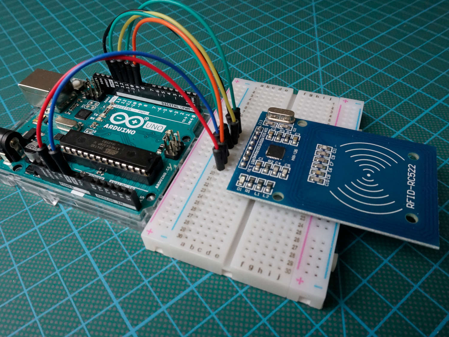
Table of Contents
What is RFID?
RFID stands for Radio-frequency identification and is an electronic communication technique mostly used to identify objects. Moreover RFID summaries all identification system which use radio frequency.
Typical use cases are:
- Identify books in a library
- Open a barrier only for specific cars
- Access employees to restricted areas using a RFID system to open doors.
The advantage compared to barcode is that there is no direct line of side required between RFID tag and reader.
Components in an RFID System
In a general RFID setup there is an RFID reader and a tag (transponder) that should be identified. The following picture shows the different components in detail.
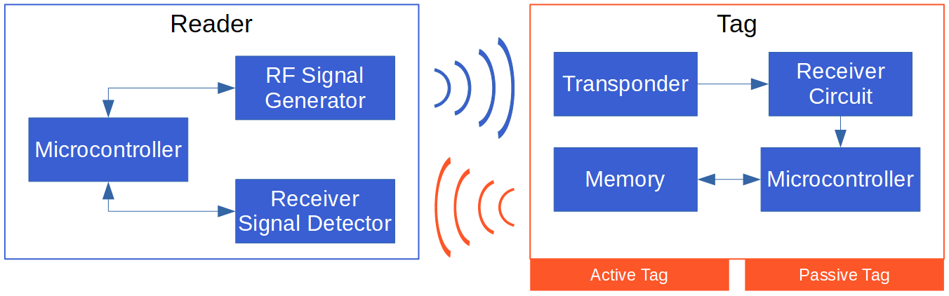
The reader consists of three parts. The radio frequency signal generator generates the electromagnetic field through a coil which is send out to power tags. There is also a receiver and signal detector to read the response of the tag The microcontroller is the head of the reader and controls the other components and further processes the information.
The tag has a transponder which receives the radio waves from the reader and also sends data back to the reader. The receiver circuit stores the energy in the tag to power the microcontroller. The microcontroller itself is connected with a memory where the information is stored which can be transmitted to the reader.
There are two fundamental different types of RFID systems:
- Passive system where tags do not have an internal source of power and therefore are powered from the RFID reader device by radio waves.
- Active system where tags are powered by a battery and can be read by a longer distance up to hundreds of meters.
The following table shows the differences of passive and active tags on different categories:
Source: OECD (2008-06-18), “RFID Guidance and Reports”, OECD Digital Economy Papers, No. 150, OECD Publishing, Paris. http://dx.doi.org/10.1787/230334062186
Power Transmission
From the table you see that in a passive RFID system the tag has no internal power supply and therefore has to be powered from the reader. The reader is sending out an electromagnetic field through an antenna coil. This electromagnetic field is received from the coil of the tag’s transponder and creates an induction voltage which serves as power supply for the microchip on the tag and is stored inside the receiver circuit.
In case of an active RFID system there is no need for a power transmission because the tag itself has an internal power supply.
Data Transmission
After the tag is powered by the induction voltage of the RFID reader, the tag sends data to the reader via load manipulation. Load is switched on and off on the tag. Because the reader and tag are inductive coupled, a change in the load at the tag results in a change of the power consumption of the readers antenna. This change in consumption is represented as voltage drop and interpreted as 1 and 0.
An other data transmission approach is data transmission via backscattered coupling. The tag creates a second electromagnetic field with the power though the first field. This second field is received by reader and through changes in the second electromagnetic field, data is transmitted.
Normally the first data that is transmitted from the tag to the reader are the UID and the PICC type which identifies the tag.
- UID: The UID is the Unique Identifier of the tag for example: “BD 31 15 2B”. The UID is saved in the first memory block of the tag and read-only. Therefore the identifier can not be changed.
- PICC: Short for Proximity Integrated Circuit Card. This is the type of tag, like that car is a Ford. For example a frequently used RFID tag for Arduino or ESP8266 microcontrollers is the MIFARE 1KB which I also use in this tutorial.
RFID Frequency Bands
In general there are different frequency bands where the RFID application can operate. The following table shows the different frequency bands.
Source: https://en.wikipedia.org/wiki/Radio-frequency_identification
RFID RC522 Module
In this tutorial I use the RC522 module as reader and also different tags which are compatible to that reader. Normally you can buy the reader with some tags as a package to make sure that the reader is able to identify the tag. It is important that the frequency is matching and that the reader supports the format of the tag.
The RC522 module is based on the Philips MF522-AN-on board and supports a RFID frequency of 13.56 MHz as well as the following tag formats: S50, S70 Ultralight, Pro, DESFire. The RC522 is connected to the Arduino or ESP8266 microcontroller via SPI which allows a transmission rate between reader and microcontroller up to 10 Mbit/s.
The current consumption is very low between 80 µA and 26 mA:
- Data transmission: 13…26 mA
- Idle state: 10…13 mA
- Sleep state: 80 µA
The tag is a Mifare transponder with 1 KB of memory which is divided into 16 sectors, each sector into 4 blocks and each block can store 2 bytes of data. Each sector has two keys (A/B) which can be assigned with rights for reading and writing memory blocks. The last block contains the keys and the rights (access conditions).
The following picture shows how the memory is build up:
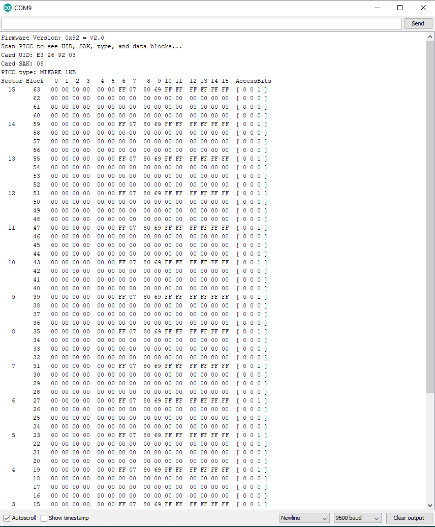
The sectors are numbered from 0 to 15 and the block number for every block (containing 2 bytes) is serially numbered from 0 to 63.
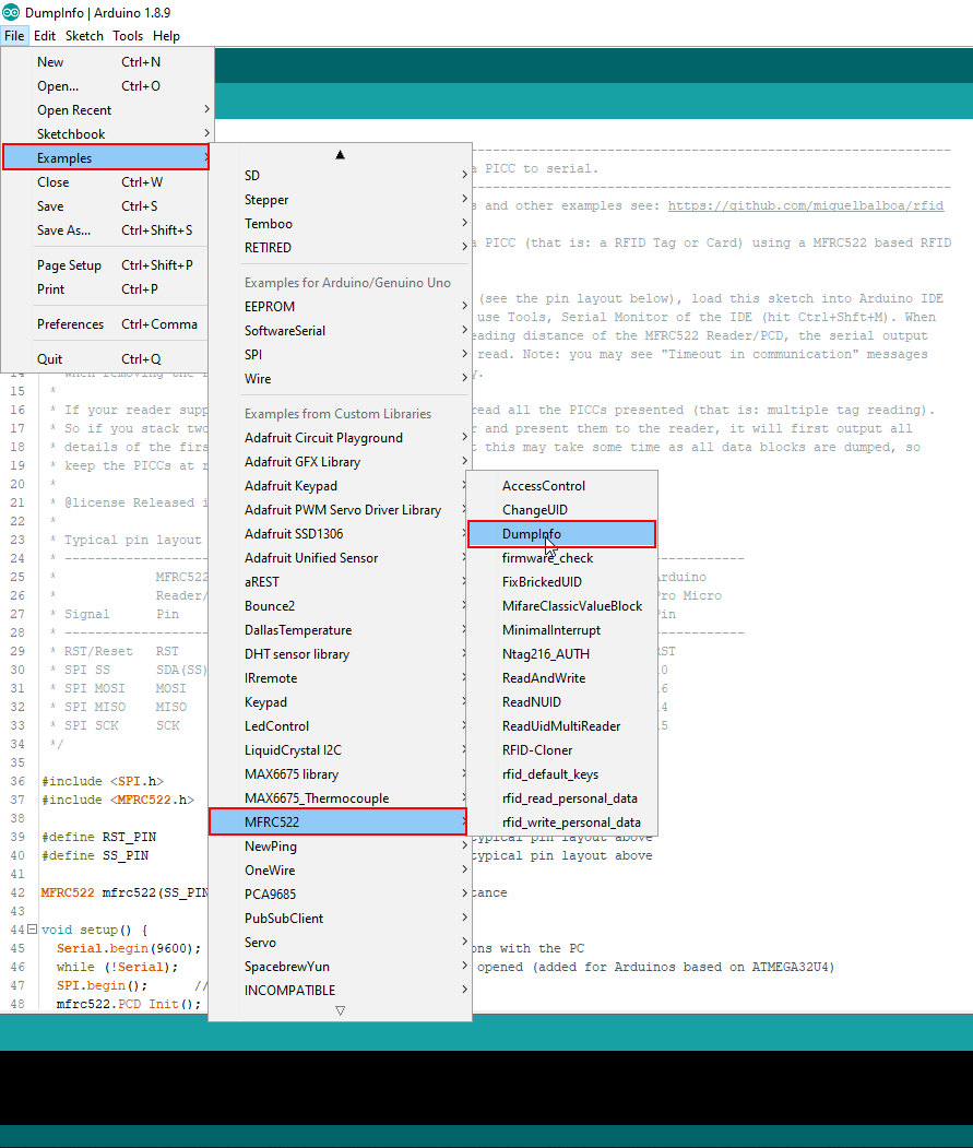
The output from the picture is called DumpInfo and is an example that comes with the installation of the MFRC522 library. The following pictures shows how you find this example: File → Examples → MFRC522 → DumpInfo
The Mifare classic has a proprietary “Crypto-1” algorithm which is not secure anymore since 2008. There are newer MIFARE DESFire EV1 and EV2 tags which are secure until today. But for some DIY projects the security is in my case not so important.
RFID reading and writing examples
The following table gives you an overview of all components and parts that I used for this tutorial. I get commissions for purchases made through links in this table.
Now we dive into the practical part of this tutorial. I prepared two examples.
- In the first example we only want to read the Unique Identifier of the tag and if this tag is valid we want to display the validation in the serial output. This example is the foundation of a secure access system.
- The second example is a little bit more complicated because we want not only read data from the tag’s memory, we also want to write data to the memory. In this example we want to create a coffee list, where we save a counter on the tag and every time the tag is recognized by the reader the counter is increased.
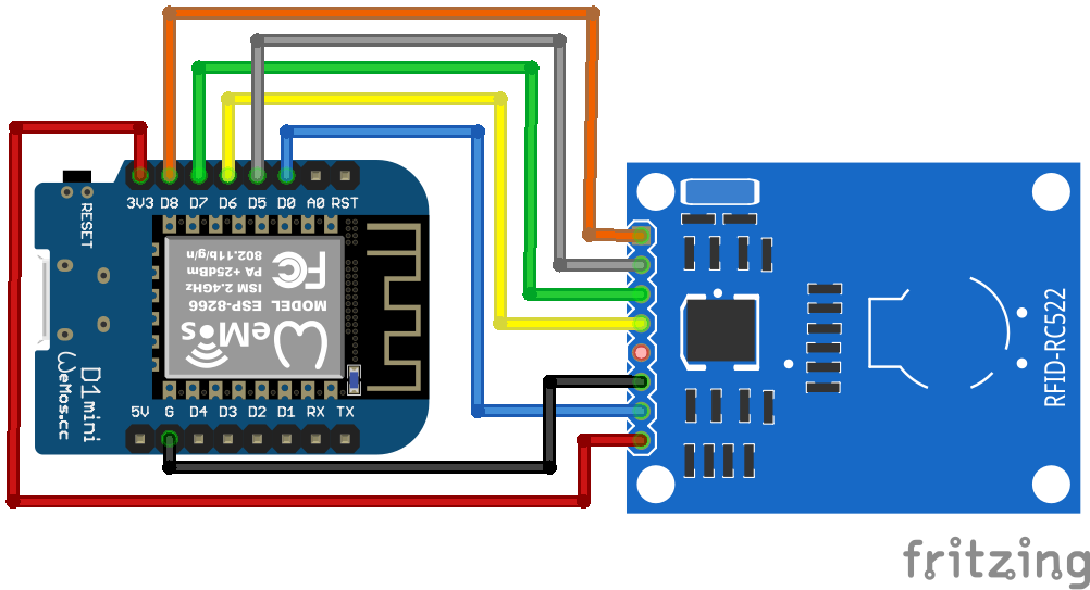
The following two pictures show the detailed connection between the devices. The connection between the microcontroller and the RC522 module will be the same in both examples.
Because the RFID reader uses SPI communication, you have to know the SPI pins on your microcontroller. If you are not sure what are the SPI pins on your micorcontroller, you find a detailed overview in the pinout blog post of the following microcontroller:
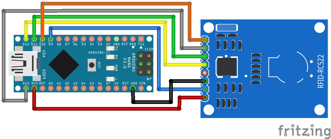
RFID RC522 Arduino Nano
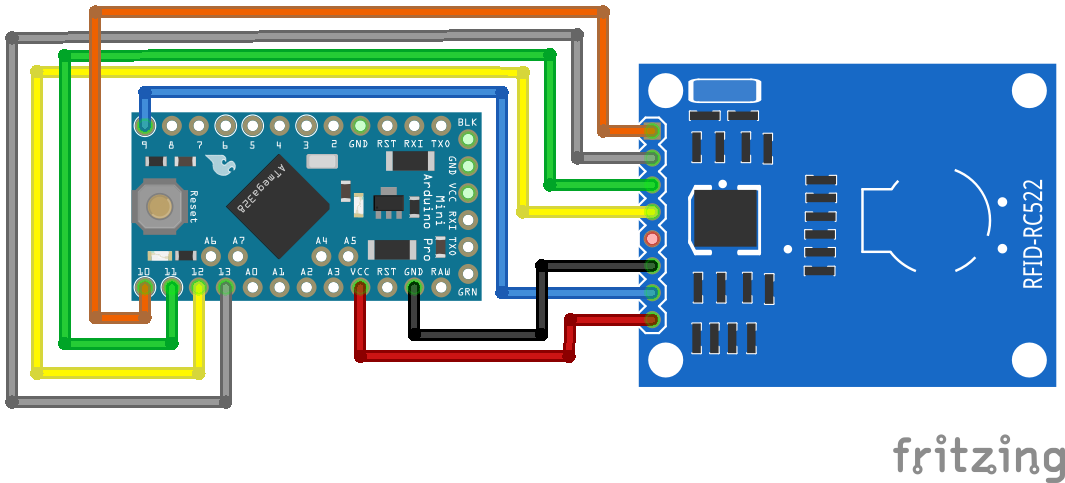
RFID RC522 Arduino Pro Mini 3.3V
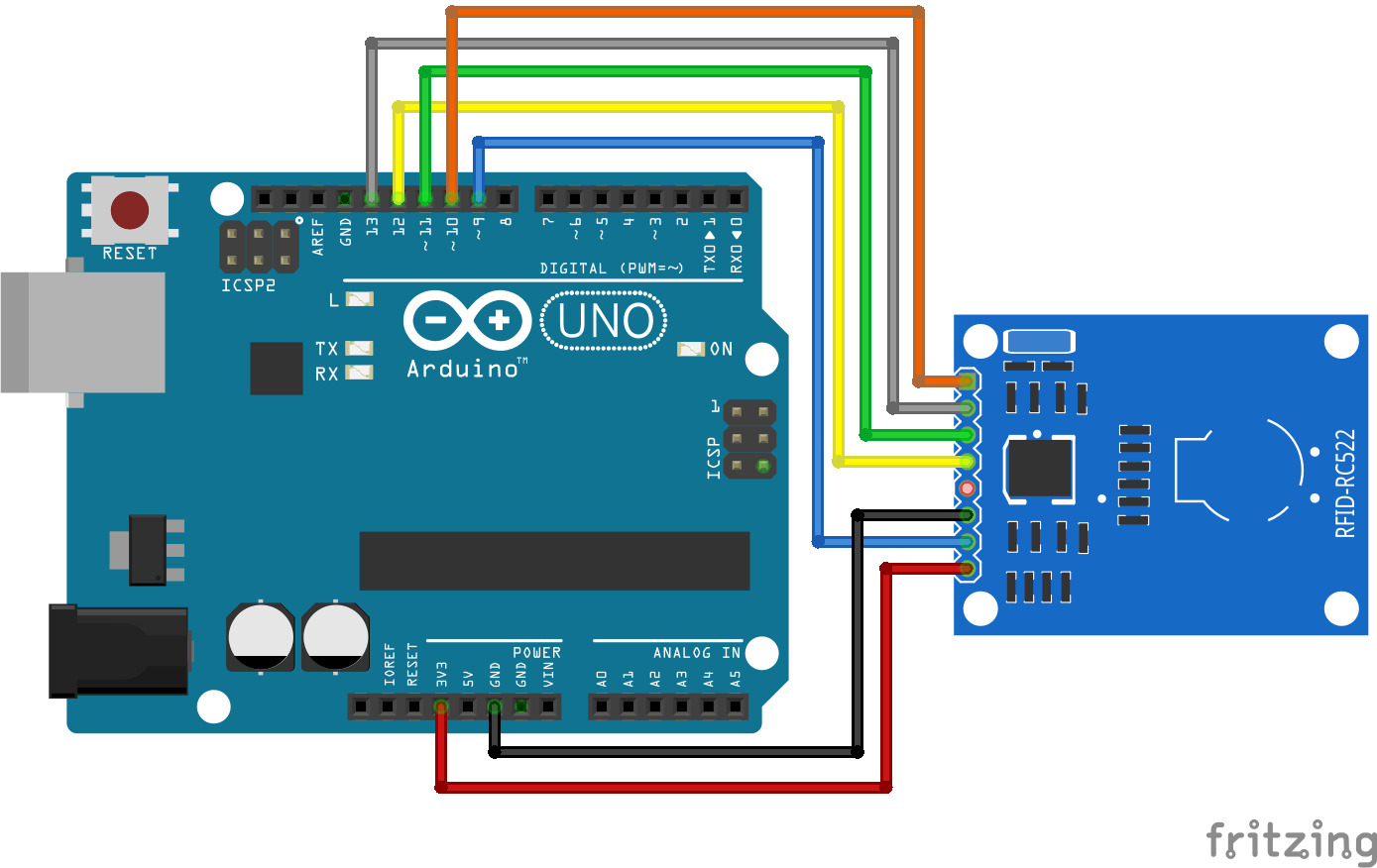
RFID RC522 Arduino Uno

RFID RC522 ESP32 NodeMCU
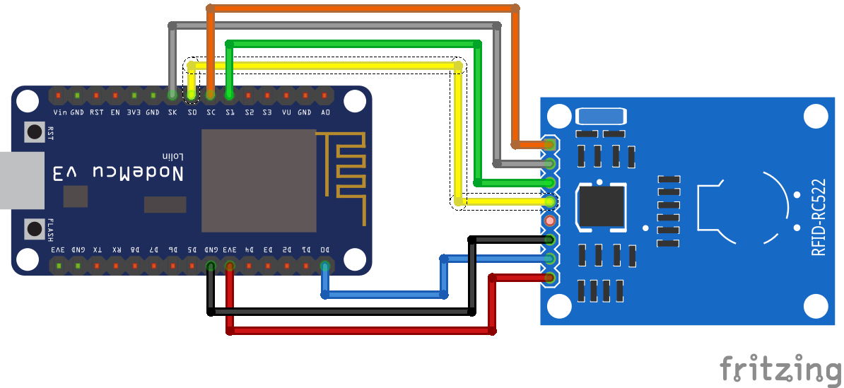
RFID RC522 ESP8266 NodeMCU
RFID RC522 ESP32 WeMos D1 Mini
At the end of this article you find a download button to download the whole program code as zip file from the two examples.
Validation of tag due to Unique Identifier
In the first example we want to read the identifier of the tag and when the identifier is valid we want to print this in the serial monitor. The valid tag is therefore defined in the program code.
#include "SPI.h"
#include "MFRC522.h"

// For Arduino Microcontroller
#define RST_PIN         9
#define SS_PIN          10

// For ESP8266 Microcontroller
//#define RST_PIN         D0
//#define SS_PIN          D8

// For ESP32 Microcontroller
//#define RST_PIN         27
//#define SS_PIN          15


MFRC522 mfrc522(SS_PIN, RST_PIN);   // Create MFRC522 instance.
MFRC522::MIFARE_Key key;
At the beginning of the script we have to include the SPI library to activate the SPI communication between the microcontroller and the RC522 module. The second library is the MFRC522 which makes it easier to handle the RFID module. You can find detailed information about the MFRC522 library by miguelbalboa in his github repository.
If you do not know how to install a library in your Arduino IDE, then you find here a step by step tutorial.
After we include the libraries we define the pin of the reset and the SPI slave select. You can see from my fritzing sketches that I choose pin 9 and 10 for the Arduino microcontroller. If you are using an ESP8266 or ESP32 microcontroller, you can uncomment the lines of code of the microcontroller and comment the two lines of code for the Arduino.
Also we create a MFRC522 instance and a key.
void dump_byte_array(byte *buffer, byte bufferSize) {
    for (byte i = 0; i < bufferSize; i++) {
        Serial.print(buffer[i] < 0x10 ? " 0" : " ");
        Serial.print(buffer[i], HEX);
    }
}

void get_UID(String content) {
  for (byte i = 0; i < mfrc522.uid.size; i++)
  {
     content.concat(String(mfrc522.uid.uidByte[i] < 0x10 ? " 0" : " "));
     content.concat(String(mfrc522.uid.uidByte[i], HEX));
  }
  content.toUpperCase();
  if (content.substring(1) == "E3 26 92 03")
  {
    Serial.println("This is the right tag");
  }
 else   {
    Serial.println("Wrong tag");
  }
}
In the setup function we first set the baud rate to 9600 which has to match to the baud rate on your serial monitor. We wait until the serial line communication is ready and initialize the SPI bus and the MFRC522 instance we created before.
Now we set the key A and B to FFFFFFFFFFFFh which is the fault key value. Because we can only upload arrays as HEX we have to use a self created function called dump_byte_array that gets a byte array and the length of the array and transfer it to HEX.
void loop() {
    // Reset the loop if no new card present on the sensor/reader. This saves the entire process when idle.
    if ( ! mfrc522.PICC_IsNewCardPresent())
        return;

    // Select one of the cards
    if ( ! mfrc522.PICC_ReadCardSerial())
        return;

    // Show some details of the PICC (that is: the tag/card)
    Serial.print(F("Card UID:"));
    dump_byte_array(mfrc522.uid.uidByte, mfrc522.uid.size);
    Serial.println();
    Serial.print(F("PICC type: "));
    MFRC522::PICC_Type piccType = mfrc522.PICC_GetType(mfrc522.uid.sak);
    Serial.println(mfrc522.PICC_GetTypeName(piccType));


    // Check for compatibility
    if (    piccType != MFRC522::PICC_TYPE_MIFARE_MINI
        &&  piccType != MFRC522::PICC_TYPE_MIFARE_1K
        &&  piccType != MFRC522::PICC_TYPE_MIFARE_4K) {
        Serial.println(F("No valid tag"));
        return;
    }

    MFRC522::StatusCode status;

    String content= "";
    get_UID(content);

    // Halt PICC
    mfrc522.PICC_HaltA();
    // Stop encryption on PCD
    mfrc522.PCD_StopCrypto1();
}
The loop function starts with checking if an RFID tag is available. If not we restart to loop function. If a tag is recognized, the tag is selected.
Next we want to display the UID and the PICC type of the tag in the serial monitor. Therefore we also use the function dump_byte_array and the function of the MFRC522 library mfrc522.uid.uidByte. To get the PICC type we use an other function of the library called mfrc522.PICC_GetType.
After we know the UID and the PICC type we have to check for compatibility. The PICC type has to be one of the following types:
- MIFARE MINI
- MIFARE 1K
- MIFARE 4K
Because the tag I use is a MIFARE 1K it is valid at this point.
Now we want to check if the card that we are currently reading is the one with the identifier that we defined as valid. First we want to make sure that the card is still available and fetch the current status with the function MFRC522::StatusCode status.
To check if it is the right card we use a second self written function called get_UID which has a string as argument. The function reads the UID again but does not display the ID to the serial monitor but checks if the ID is “E3 26 92 03”. If it is the same ID then we print the result to the serial monitor and if it is the wrong ID we print that it is the wrong tag.
At the end of the loop function we halt the PICC and stop the encryption of the PCD.
void dump_byte_array(byte *buffer, byte bufferSize) {
for (byte i = 0; i < bufferSize; i++) {
Serial.print(buffer[i] < 0x10 ? " 0" : " ");
Serial.print(buffer[i], HEX);
}
}
void get_UID(String content) {
for (byte i = 0; i < mfrc522.uid.size; i++)
{
content.concat(String(mfrc522.uid.uidByte[i] < 0x10 ? " 0" : " "));
content.concat(String(mfrc522.uid.uidByte[i], HEX));
}
content.toUpperCase();
if (content.substring(1) == "E3 26 92 03")
{
Serial.println("This is the right tag");
}
else {
Serial.println("Wrong tag");
}
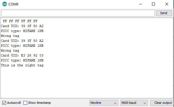
} The following picture shows that I tried to get access two times with a tag that ID is “39 3F 50 A2” and that the program code is running correct, telling me that it is the wrong ID. The third attempt was the valid tag and I got access.
Automated Coffee Counter
In this second example we want not only read out a specific memory block of the tag, we also want to write into this block. In this example we create a coffee list where each time an employee gets a coffee her or his tag is scanned by the reader. The reader increases the bit we choose to count the coffees and write the increased counter back to the tag.
Also we want to have a master tag which enables the option to reset the coffee counter to 0. If someone pays the bill, the master tag is identified by the reader and the counter of the next tag will be reset.
A lot of the program code is the same compared to the first example. Therefore I only describe the changes and additional code lines.
#include "SPI.h"
#include "MFRC522.h"

// For Arduino Microcontroller
#define RST_PIN         9
#define SS_PIN          10

// For ESP8266 Microcontroller
//#define RST_PIN         D0
//#define SS_PIN          D8

// For ESP32 Microcontroller
//#define RST_PIN         27
//#define SS_PIN          15


MFRC522 mfrc522(SS_PIN, RST_PIN);   // Create MFRC522 instance.
MFRC522::MIFARE_Key key;

byte sector         = 1;  //  Number of sector to write
byte blockAddr      = 4;  // Number of block to write
byte dataBlock[]    = {
    0x00, 0x00, 0x00, 0x00,
    0x00, 0x00, 0x00, 0x00,
    0x00, 0x00, 0x00, 0x00,
    0x00, 0x00, 0x00, 0x00};

byte reset_counter = 0;

byte trailerBlock = 7;  // Block address
byte buffer[18];
In the first section we have to add some more variables:
- byte sector: we want to write our coffee counter in the first sector.
- byte blockAddr: in the first sector we choose the fourth block for the counter.
- byte dataBlock: is the array which is written to the fourth block in the first sector and defined as HEX.
- byte reset_counter: is a flag we set when the master tag was read. This flag indicates to reset the counter or not.
- byte trailerBlock: defines the block where the key A and key B is stored.
- byte buffer: is the array that is filled when we read out the block 4 of the tag’s memory.
void setup() {
    Serial.begin(9600); // Initialize serial communications with the PC
    while (!Serial);    // Do nothing if no serial port is opened (added for Arduinos based on ATMEGA32U4)
    SPI.begin();        // Init SPI bus
    mfrc522.PCD_Init(); // Init MFRC522 card

    // Prepare the key (used both as key A and as key B)
    // using FFFFFFFFFFFFh which is the default at chip delivery from the factory
    for (byte i = 0; i < 6; i++) {
        key.keyByte[i] = 0xFF;
    }
    dump_byte_array(key.keyByte, MFRC522::MF_KEY_SIZE);
    Serial.println();
}
The setup function is 1:1 the same from the previous example.
void loop() {
    // Reset the loop if no new card present on the sensor/reader. This saves the entire process when idle.
    if ( ! mfrc522.PICC_IsNewCardPresent())
        return;

    // Select one of the cards
    if ( ! mfrc522.PICC_ReadCardSerial())
        return;


    byte size = sizeof(buffer);

    // Show some details of the PICC (that is: the tag/card)
    Serial.print(F("Card UID:"));
    dump_byte_array(mfrc522.uid.uidByte, mfrc522.uid.size);
    Serial.println();
    Serial.print(F("PICC type: "));
    MFRC522::PICC_Type piccType = mfrc522.PICC_GetType(mfrc522.uid.sak);
    Serial.println(mfrc522.PICC_GetTypeName(piccType));


    // Check for compatibility
    if (    piccType != MFRC522::PICC_TYPE_MIFARE_MINI
        &&  piccType != MFRC522::PICC_TYPE_MIFARE_1K
        &&  piccType != MFRC522::PICC_TYPE_MIFARE_4K) {
        Serial.println(F("This sample only works with MIFARE Classic cards."));
        return;
    }

    MFRC522::StatusCode status;

    authenticate_key_A();

    read_sector(size);

    compute_coffee_counter();

    authenticate_key_B();

    write_block();

    check_block();


    String content= "";
    reset_counter_function(content);


    // Halt PICC
    mfrc522.PICC_HaltA();
    // Stop encryption on PCD
    mfrc522.PCD_StopCrypto1();
}
The loop function starts and ends the same compared to the first example. Only the length of the buffer array is recalculated each time because this length could change when writing to the tag. In the middle part we execute a couple more functions which I describe in the next section of this tutorial:
- authenticate_key_A(): before we can read the values of block 4 we have to authenticate with key A.
- read_sector(): after the authentication we read the block 4.
- compute_coffee_counter(): either we increase the coffee counter in block 4 or reset the counter.
- authenticate_key_B(): then we need another authentication with key B before we can write the changed values to block 4.
- write_block(): write the new content to block 4.
- check_block(): Check if the block was written correctly or if the transmission was interrupted.
void dump_byte_array(byte *buffer, byte bufferSize) {
    for (byte i = 0; i < bufferSize; i++) {
        Serial.print(buffer[i] < 0x10 ? " 0" : " ");
        Serial.print(buffer[i], HEX);
    }
}
The function dump_byte_array is the same as in the first example.
void reset_counter_function(String content) {
  for (byte i = 0; i < mfrc522.uid.size; i++)
  {
     content.concat(String(mfrc522.uid.uidByte[i] < 0x10 ? " 0" : " "));
     content.concat(String(mfrc522.uid.uidByte[i], HEX));
  }
  content.toUpperCase();
  if (content.substring(1) == "E3 26 92 03")
  {
    reset_counter = 1;
  }

 else   {
    reset_counter = 0;
  }
}
The function to reset the counter is nearly the same as in the first example to decide if the UID is valid or not. But in this example we change the reset_counter variable to 1 if we want to reset the counter for the next tag or if we leave the variable to 0, indicating that the counter has to be incremented by 1.
void compute_coffee_counter() {
  // Read current coffee counter and increase the counter or reset to 0
  int coffee_counter = buffer[0];
  Serial.print("Your old coffee counter is: ");
  Serial.println(coffee_counter);

  Serial.print("Status reset: ");
  Serial.println(reset_counter);

  if (reset_counter == 1) {
    dataBlock[0] = 0;
    reset_counter = 0;
  }
  else {
    dataBlock[0] = coffee_counter+1;
  }

  Serial.print("Your new coffee counter is: ");
  Serial.println(dataBlock[0]);
}
Now we want to change the counter. Therefore we read the first element of the buffer array and save this value to the variable coffee_counter as integer. We print the old value of the counter to the serial monitor and evaluate the variable reset_counter as mentioned before. If reset_counter is 1, the previous read tag was the master tag and we set the counter to 0 and also reset the variable reset_counter. If there was no master tag we increase the counter by 1.
void authenticate_key_A() {
  // Authenticate using key A
  Serial.println(F("Authenticating using key A..."));
  MFRC522::StatusCode status = (MFRC522::StatusCode) mfrc522.PCD_Authenticate(MFRC522::PICC_CMD_MF_AUTH_KEY_A, trailerBlock, &key, &(mfrc522.uid));
  if (status != MFRC522::STATUS_OK) {
      Serial.print(F("PCD_Authenticate() failed: "));
      Serial.println(mfrc522.GetStatusCodeName(status));
      return;
  }
}

void authenticate_key_B() {
  // Authenticate using key B
  Serial.println(F("Authenticating again using key B..."));
  MFRC522::StatusCode status = (MFRC522::StatusCode) mfrc522.PCD_Authenticate(MFRC522::PICC_CMD_MF_AUTH_KEY_B, trailerBlock, &key, &(mfrc522.uid));
  if (status != MFRC522::STATUS_OK) {
      Serial.print(F("PCD_Authenticate() failed: "));
      Serial.println(mfrc522.GetStatusCodeName(status));
      return;
  }
}
The two function for the authentication use the function mfrc522.PCD_Authenticate from the library. After the authentication we can read or write to different block of the memory.
void read_sector(byte size) {
  // Show the whole sector as it currently is
  Serial.println(F("Current data in sector:"));
  mfrc522.PICC_DumpMifareClassicSectorToSerial(&(mfrc522.uid), &key, sector);
  Serial.println();

  // Read data from the block
  Serial.print(F("Reading data from block ")); Serial.print(blockAddr);
  Serial.println(F(" ..."));
  MFRC522::StatusCode status = (MFRC522::StatusCode) mfrc522.MIFARE_Read(blockAddr, buffer, &size);
  if (status != MFRC522::STATUS_OK) {
      Serial.print(F("MIFARE_Read() failed: "));
      Serial.println(mfrc522.GetStatusCodeName(status));
  }
  Serial.print(F("Data in block ")); Serial.print(blockAddr); Serial.println(F(":"));
  dump_byte_array(buffer, 16);
  Serial.println();
}
The next function reads the data from the memory sector and uses the library function mfrc522.MIFARE_Read with the address of the block, the array to save the block data and the size of the array as argument.
void write_block(){
  // Write data to the block
  Serial.print(F("Writing data into block ")); Serial.print(blockAddr);
  Serial.println(F(" ..."));
  dump_byte_array(dataBlock, 16);
  Serial.println();
  MFRC522::StatusCode status = (MFRC522::StatusCode) mfrc522.MIFARE_Write(blockAddr, dataBlock, 16);
  if (status != MFRC522::STATUS_OK) {
      Serial.print(F("MIFARE_Write() failed: "));
      Serial.println(mfrc522.GetStatusCodeName(status));
  }
  Serial.println();
}
The block to write to the memory is not too much different from the reading function but the library function mfrc522.MIFARE_Write instead of read is used.
void check_block(){
  // Check that data in block is what we have written
  // by counting the number of bytes that are equal
  Serial.println(F("Checking result..."));
  byte count = 0;
  for (byte i = 0; i < 16; i++) {
      // Compare buffer (= what we've read) with dataBlock (= what we've written)
      if (buffer[i] == dataBlock[i])
          count++;
  }
  Serial.print(F("Number of bytes that match = ")); Serial.println(count);
  if (count == 16) {
      Serial.println(F("Success :-)"));
  } else {
      Serial.println(F("Failure, no match :-("));
      Serial.println(F("  perhaps the write didn't work properly..."));
  }
  Serial.println();

  // Dump the sector data
  Serial.println(F("Current data in sector:"));
  mfrc522.PICC_DumpMifareClassicSectorToSerial(&(mfrc522.uid), &key, sector);
  Serial.println();
}
The last function check_block() compares the buffer element by element and also the size of the buffer. If the data was not written correctly the data is dumped and you have to start the writing of the coffee list again.
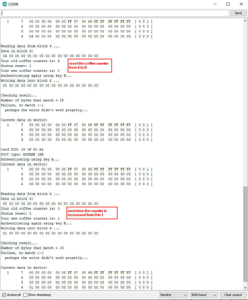
The following picture of the serial monitor shows how I increase the coffee counter and also that I reset the counter from 4 to zero. It is also possible not to reset the counter but to decrease the counter by 1 if the master tag was previously detected by the reader.
I hope you like this tutorial and if you have any questions, please use the comment section below to ask you questions. I answer them as comment as soon as possible.
Hi, great explanation, are you in freelancer?
I need some custom work to be done like this
Plz email your ID to gsuresh2u@gmail.com
Hi Suresh,
thanks for your comment. Unfortunately I do not any freelancing stuff.
hi that was great, thank you for your explanation I just have one question; what is the total of your coffee counter? truly appreciate your reply 🙂
How to make Rfid using arduino
Hi Mario,
I think that I do not understand your question? The article shows how to use RFID with Arduino microcontrollers.
Well done aand written!
I started writing a blog in the past ffew weeks and npticed that many blogs merely rework old ideas but addd very little of value.
It’s good to see a helpful post of some teue value to your readers and me.
It iss going down on the list of creteria I need to emulate as a new blogger.
Visitor engagement and content quality are king.
Many wonderful thoughts; you have unquestionably managed to get on mmy list of bllgs to follow!
Continue the terrific work!
Congratulations,
Grethel
Hello,
thank you for this very nice tutorial.
Just one remark :
in the “check-block” function , I think that
for (byte i = 0; i < 16; i++)
must be replaced by
for (byte i = 0; i < 15; i++)
so the check returns no error.
Regards,
Yves
DO I HAVE A CHANCE TO CHANGE MY CARD READER NAME?
HOW CAN IT BE POSSIBLE?
Hi Ismail,
what do you mean with the name of the card reader?
Rc522 den 9 adet kullanacağım. Nasıl bir yol izlemeliyim
Congratulations.. excellent your material.
I have a doubt about rc522. There are some things to test if device are working correctly? I connect rc522 in a esp32.. the pin are simple.. but I can’t to do work♂️..
Thanks
Silvio
Hi, thanks for this tutorial,
So i have a problem, i need to use rc522 rfid reader+microcontroller(arduino or raspberry pi or esp8266) and i need to upload data’s rfid to web server. What type of microcontroller is suitable for uploading data to a web server?
Thanks, I’m a beginner in electronic programming