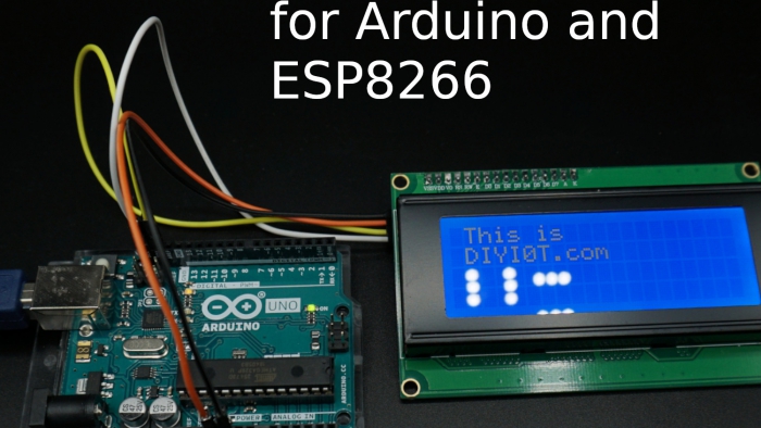
LCD Display Tutorial for Arduino, ESP8266 and ESP32
In this tutorial you learn how to connect your microcontroller with a LCD display and how to make your first sketch to display whatever you want on the LCD screen.
We use different kinds of displays:
- LCD display without I2C connection
- LCD display with I2C connection
As bonus I show you how you can create custom characters like a heart on the screen super fast and easy.
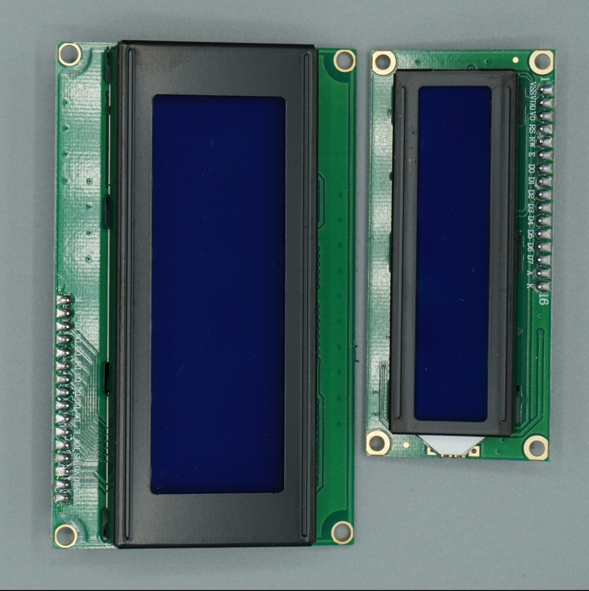
Table of Contents
Most of the time we use the serial plotter of the Arduino IDE to visualize our solutions or output of a sketch. This is great and a big time saver when you are doing prototyping. But there is a time when your system will go live. If you are for example only sending data from sensors to a database on a Raspberry Pi, than you are able to view the output remote from your PC by connecting to the database. But there are use cases like an indoor weather station, where you want to see the output like the current temperature directly and not when you are on you PC.
Than displays are the way to go. There are different kinds of displays like 7 Segment LED display, 4 Digit 7 Segment display, 8×8 Dot Matrix display, OLED display or the easiest and cheapest version the liquid crystal display (LCD).
Most LCD displays have either 2 rows with 16 characters per row or 4 rows with 20 characters per row. There are LCD screen with and without I2C module. I highly suggest the modules with I2C because the connection to the board is very easy and there are only 2 instead of 6 pins used. But we will cover the LCD screen with and without I2C module in this article.
The following table gives you an overview of all components and parts that I used for this tutorial. I get commissions for purchases made through links in this table.
| Arduino Uno | Amazon | Banggood | AliExpress | |
| OR | ESP8266 NodeMCU | Amazon | Banggood | AliExpress |
| OR | ESP32 NodeMCU | Amazon | Banggood | AliExpress |
| AND | LCD Display 20×4 with I2C | Amazon | Banggood | AliExpress |
| AND | LCD Display 16×2 with I2C | Amazon | Banggood | AliExpress |
| OR | LCD Display 20×4 without I2C | Amazon | Banggood | AliExpress |
| OR | LCD Display 16×2 without I2C | Amazon | Banggood | AliExpress |
Features of the LCD display
The LCD display has an operating voltage between 4.7V and 5.3V with a current consumption of 1mA without backlight and 120mA with full backlight. There are version with a green and also with a blue backlight color. Each character of the display is build by a 5×8 pixel box and is therefore able to display custom generated characters. Because each character is build by (5×8=40) 40 pixels a 16×2 LCD display will have 16x2x40= 1280 pixels in total. The LCD module is able to operate in 8-bit and 4-bit mode. The difference between the 4-bit and 8-bit mode are the following:
- In 8-bit mode only one pulse signal is required to display a character on LCD display instead of two pulse signals.
- 4-bit mode make use of only just four data pins compared to all 8 data pins in the 8-bit mode.
- Since two pulse (enable) signals are required to display a single character the 4-bit mode latency time is higher compared to the 8-bit mode.
LCD display without I2C connection
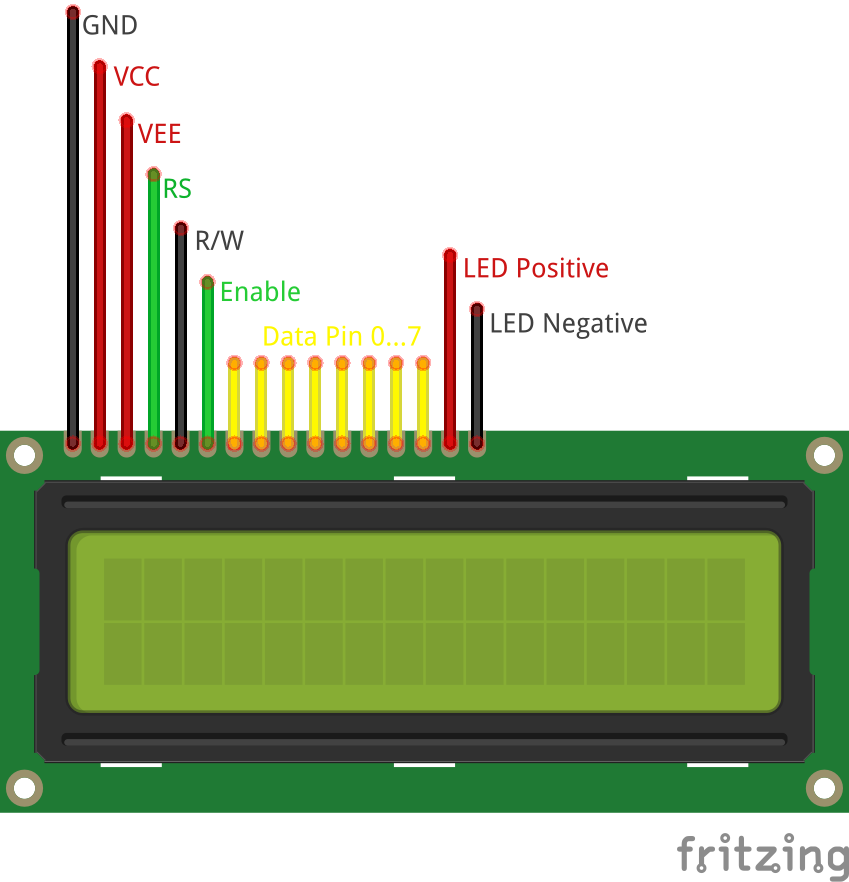
If we use the LCD display version without I2C connection we have to add the potentiometer manually to control the contrast of the screen. The following picture shows the pinout of the LCD screen.
Also I added a table how to connect the LCD display with the Arduino Uno and the NodeMCU with a description of the LCD pin. To make it as easy as possible for you to connect your microcontroller to the display, you find the corresponding fritzing connection picture for the Arduino Uno and the NodeMCU in this chapter.
| Pin NR | LCD-016M002B pin label | Arduino Uno connection | NodeMCU connection | Description |
| 1 | GND | GND | GND | Ground pin to connected to the GND pin of the Arduino. |
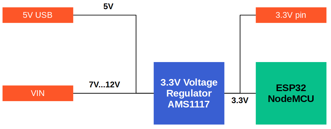
| 2 | VCC | 3V3 / 5V | 3V3 / VIN | Voltage supply of 5V (4.7V – 5.3V). Also for a test 3V does the job. |
| 3 | VEE | Potentiometer | Potentiometer | Adjusts the contrast of the display If this pin is grounded, you get the maximum contrast. We will connect the VEE pin to the potentiometer output to adjust the contrast by changing the resistance of the potentiometer. |
| 4 | RS | D12 | D2 | Select command register to low when we are sending commands to the LCD like set the cursor to a specific location, clear the display or turn off the display. |
| 5 | R/W | GND | GND | And select data register when RS is set to high to send data or characters to the LCD. |
| 6 | Enable | D11 | D3 | Differ between read or write data. Normally grounded to write data to LCD |
| 7 | Data Pin 0 (d0) | Connected to microcontroller pin and toggled between 1 and 0 for data acknowledgement. So if we want to send data via the data pins 0 to 7, we have to make sure that the enable pin is high. | ||
| 8 | Data Pin 1 (d1) | Data pins 0 to 7 forms an 8-bit data line. The Data Pins are connection to the Digital I/O pins of the microcontroller to send 8-bit data. These LCD’s can also operate on 4-bit mode in such case Data pin 4,5,6 and 7 will be left free. | ||
| 9 | Data Pin 2 (d2) | |||
| 10 | Data Pin 3 (d3) | |||
| 11 | Data Pin 4 (d4) | D5 | D6 | |
| 12 | Data Pin 5 (d5) | D4 | D7 | |
| 13 | Data Pin 6 (d6) | D3 | D8 | |
| 14 | Data Pin 7 (d7) | D2 | RX | |
| 15 | LED Positive | 3V3 / 5V | 3V3 / VIN | Backlight LED pin positive terminal |
| 16 | LED Negative | GND | GND | Backlight LED pin negative terminal |
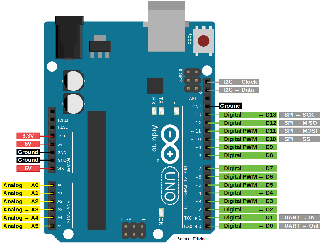
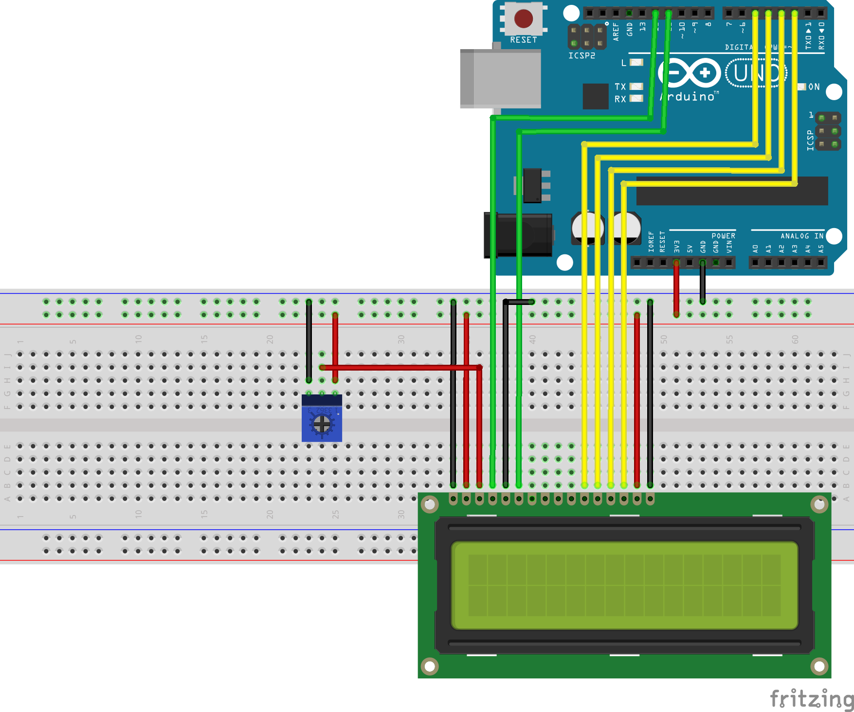
LCD display connection to the Arduino Uno without I2C
The following picture shows the connections between the LCD display and the Arduino Uno.
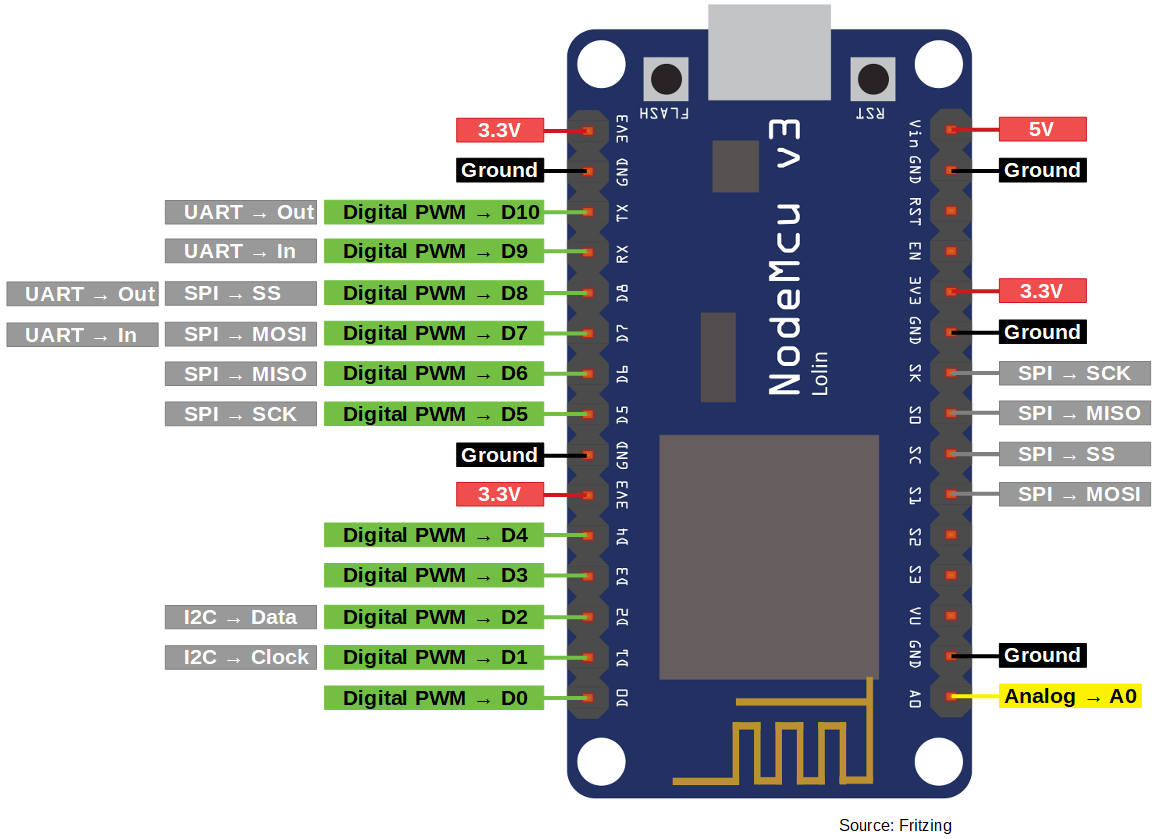
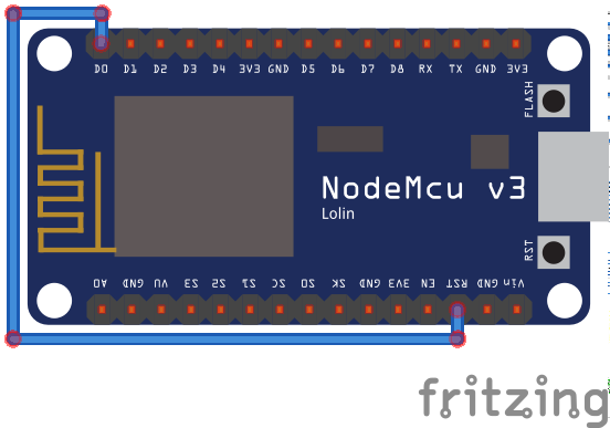
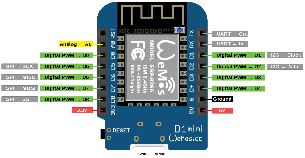
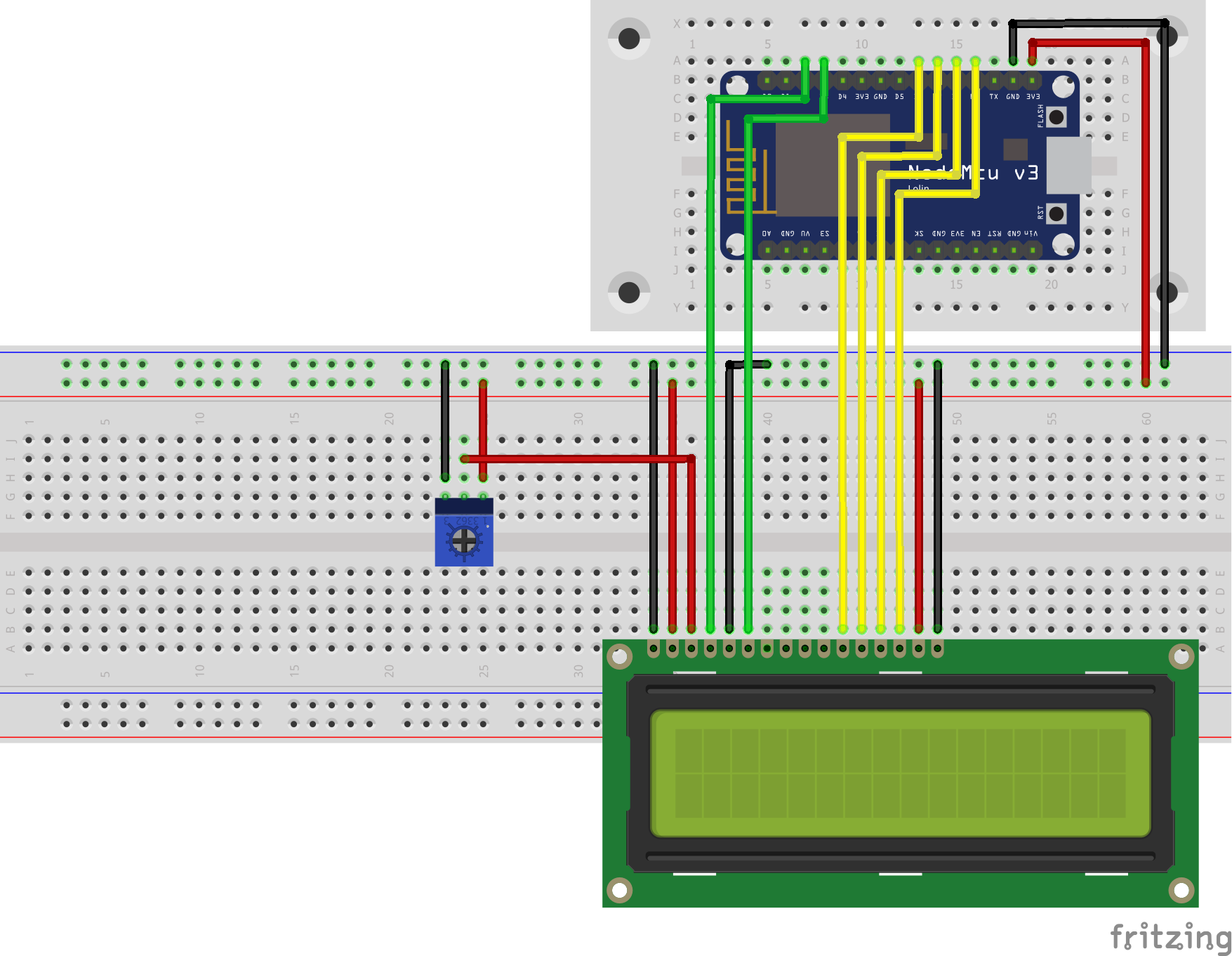
LCD display connection to the NodeMCU without I2C
The following picture shows the connections between the LCD display and the NodeMCU.
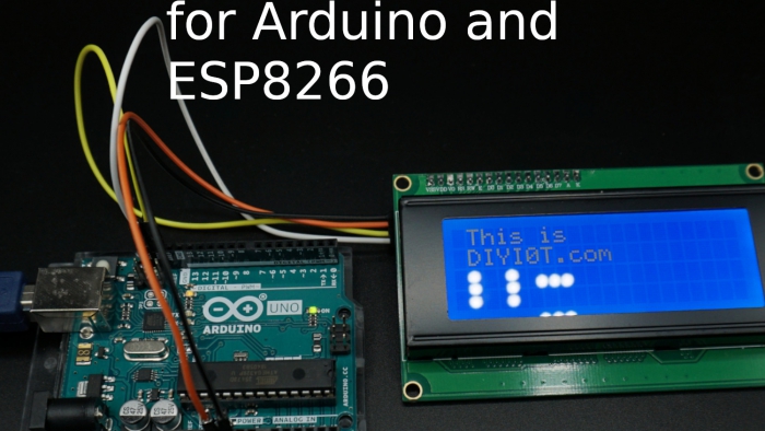
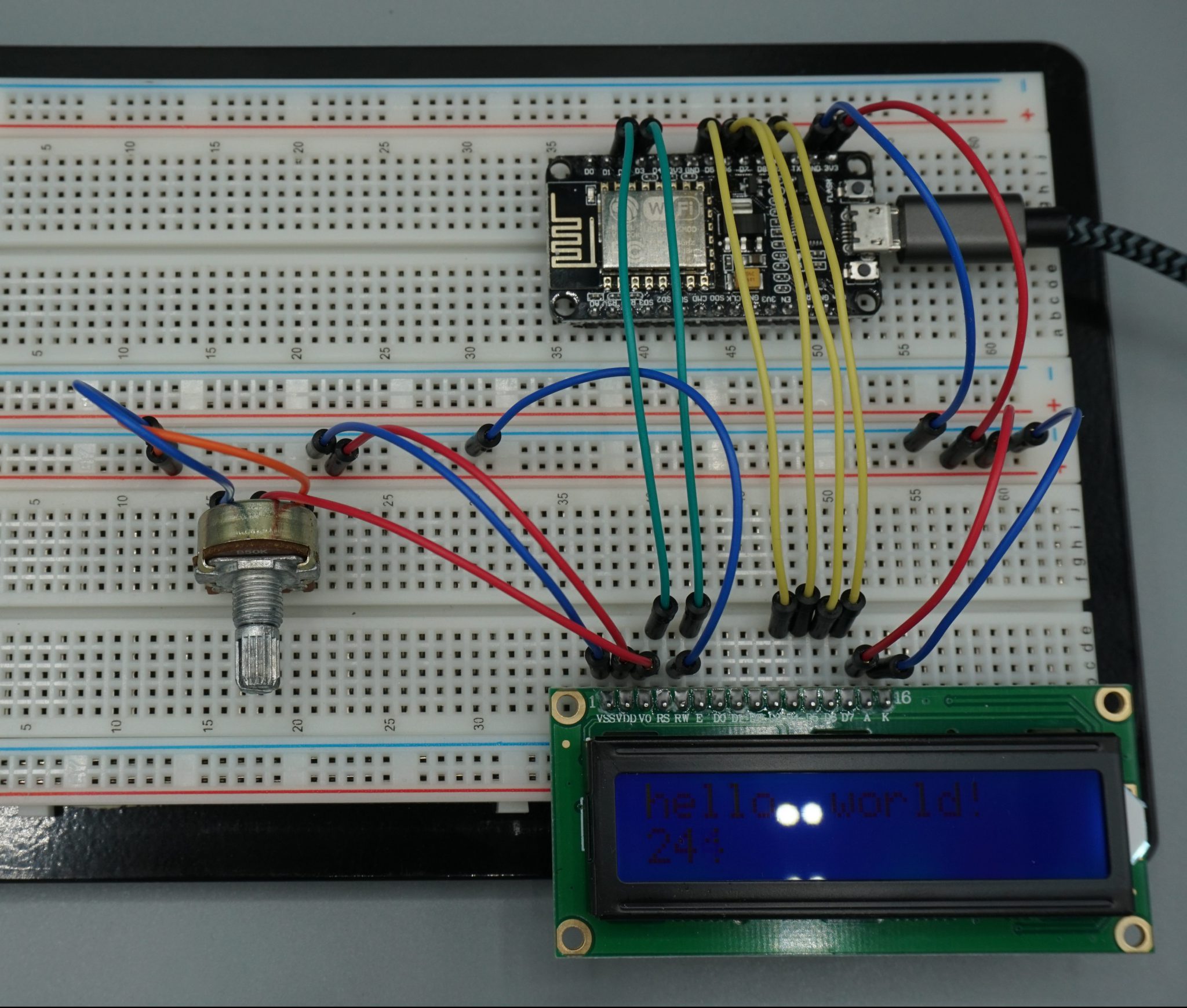
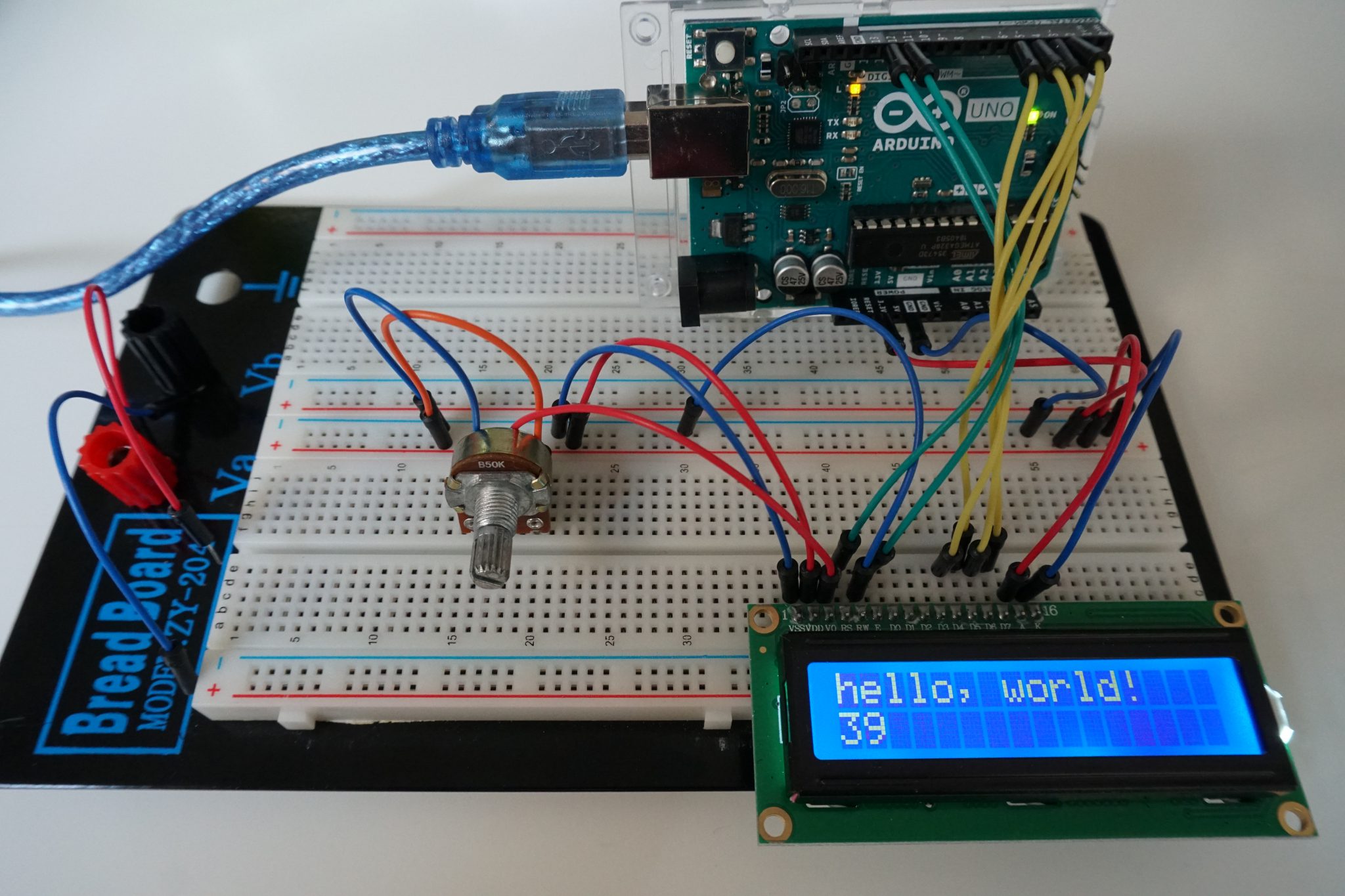
Of cause we want to try the connection between the microcontroller and the LCD display. Therefore you find an example sketch in the Arduino IDE. The following section shows the code for the sketch and a picture of the running example, more or less because it is hard to make a picture of the screen ;-). The example prints “hello, world!” in the first line of the display and counts every second in the second row. We use the connection we described before for this example.
// include the library code:
#include "LiquidCrystal_I2C.h"

// initialize the library by associating any needed LCD interface pin
// with the arduino pin number it is connected to
const int RS = D2, EN = D3, d4 = D5, d5 = D6, d6 = D7, d7 = D8;

// if you use the NodeMCU 12E the suggested pins are
// const int RS = 4, EN = 0, d4 = 12 , d5 = 13, d6 = 15, d7 = 3;

LiquidCrystal lcd(RS, EN, d4, d5, d6, d7);

void setup() {
// set up the LCD's number of columns and rows:
lcd.begin(16, 2);
// Print a message to the LCD.
lcd.print("hello, world!");
}

void loop() {
// set the cursor to column 0, line 1
// (note: line 1 is the second row, since counting begins with 0):
lcd.setCursor(0, 1);
// print the number of seconds since reset:
lcd.print(millis() / 1000);
}
Looks very complicated to print data onto the LCD screen. But don’t worry like in most cases if it starts to get complicated, there is a library to make the word for us. This is also the case for the LCD display without I2C connection.
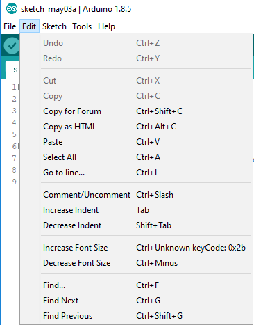
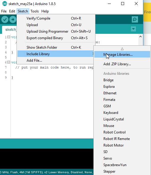
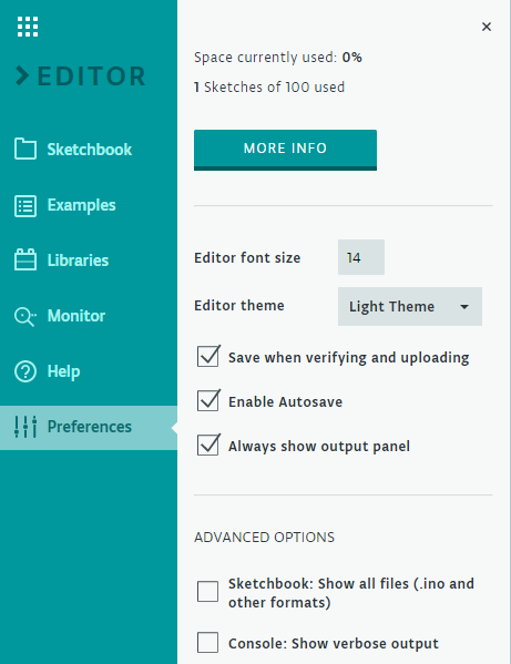
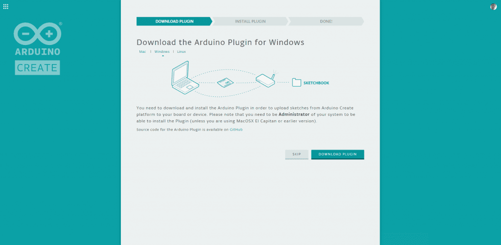
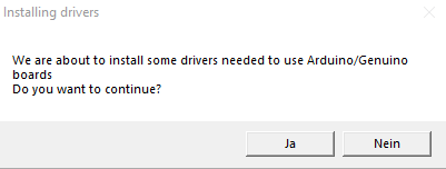
Therefore the next step is to install the library “LiquidCrystal”. You find here an article how to install an external library via the Arduino IDE. After you installed the library successful you can include the library via: #include < LiquidCrystal.h>.
LCD display with I2C connection
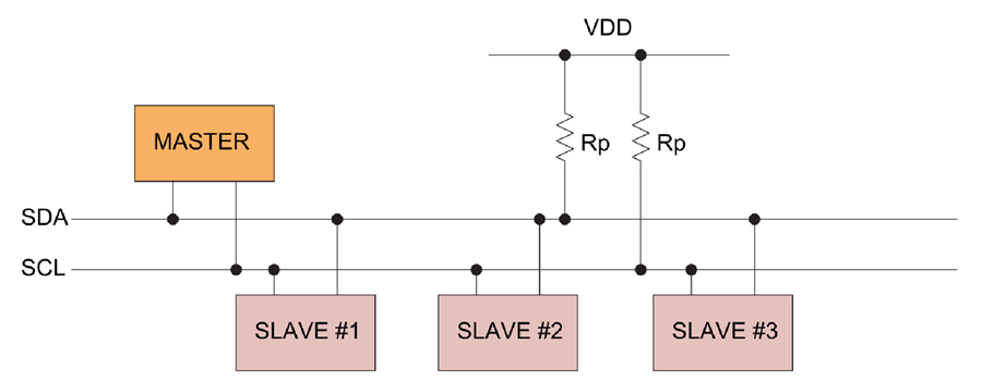
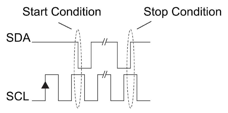
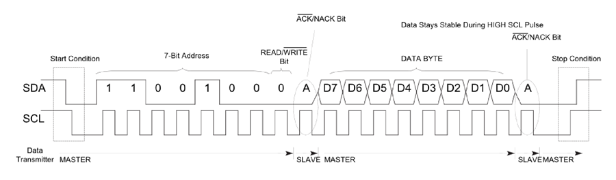
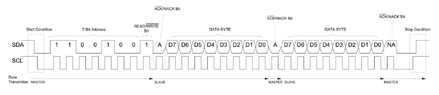
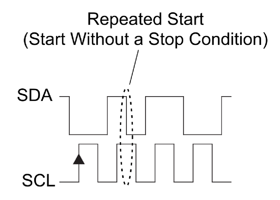
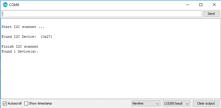
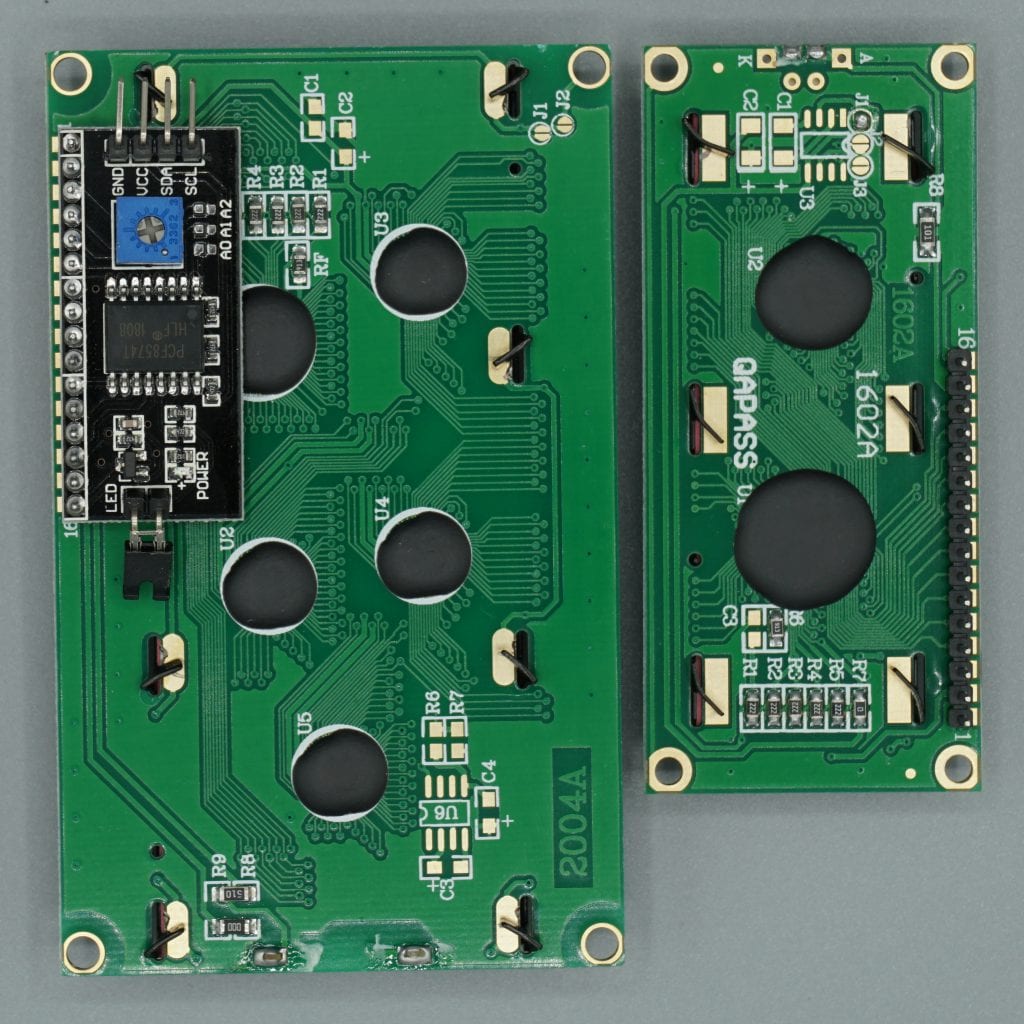
Like I told you, I would suggest the LCD modules with I2C because you only need 2 instead of 6 pins for the connection between display and microcontroller board. In the case you use the I2C communication between LCD and microcontroller, you need to know the I2C HEX address of the LCD. In this article I give you a step by step instruction how to find out the I2C HEX address of a device. There is also an article about the I2C communication protocol in detail.
On the backside is a 10 kΩ potentiometer build in to control the screen contrast. You do not have to add the potentiometer manually like in the version without I2C connection.
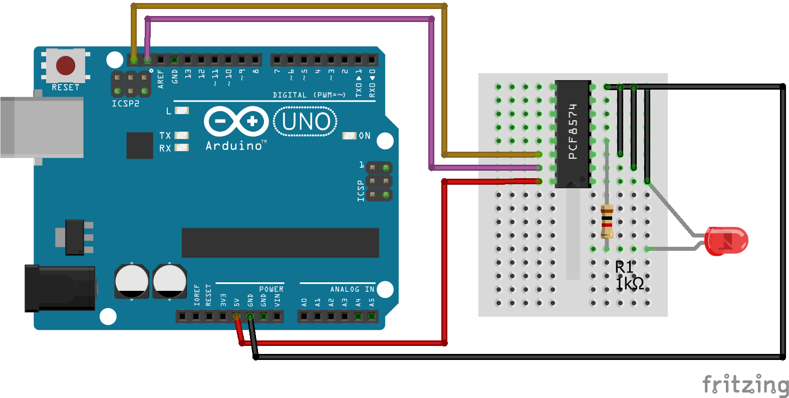
The following picture shows how to connect an I2C LCD display with an Arduino Uno. We will use exact this connection for all of the examples in this article.

Arduino Uno
GND
5V
PIN18
PIN19
I2C LCD Display
GND
VCC
SDA
SCL
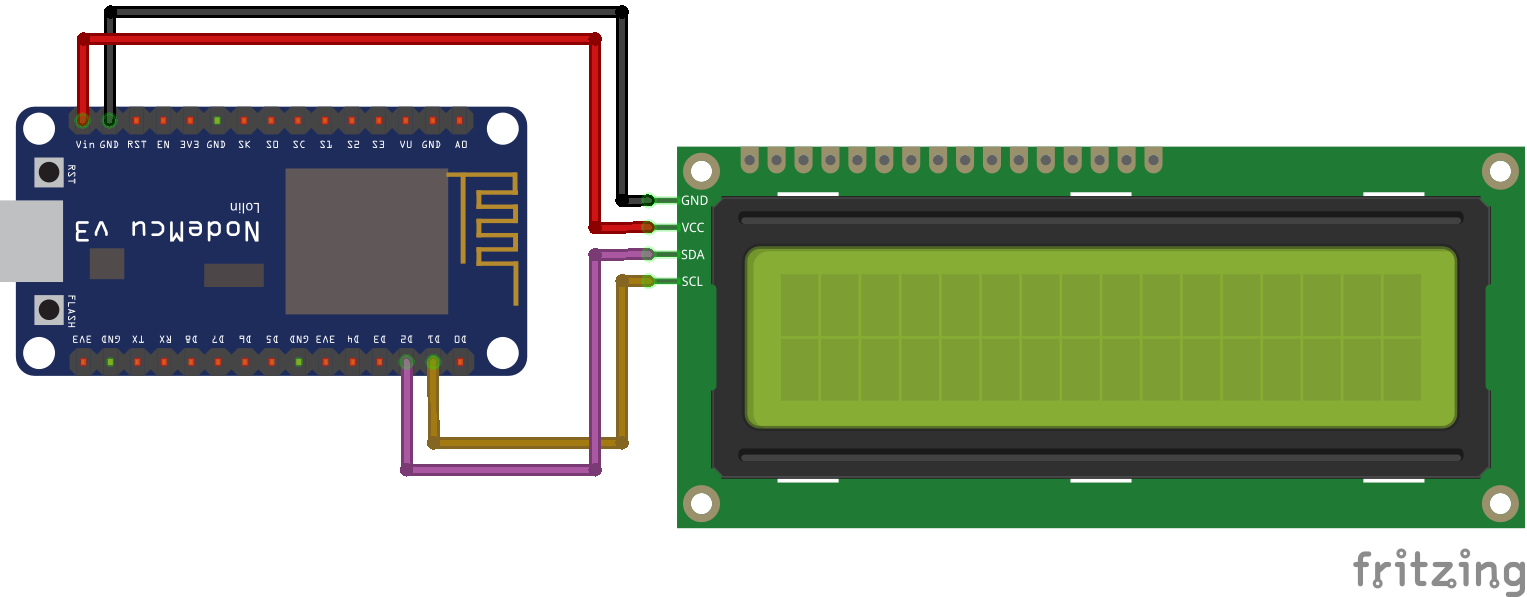
NodeMCU
GND
VIN
D2
D1
I2C LCD Display
GND
VCC
SDA
SLC
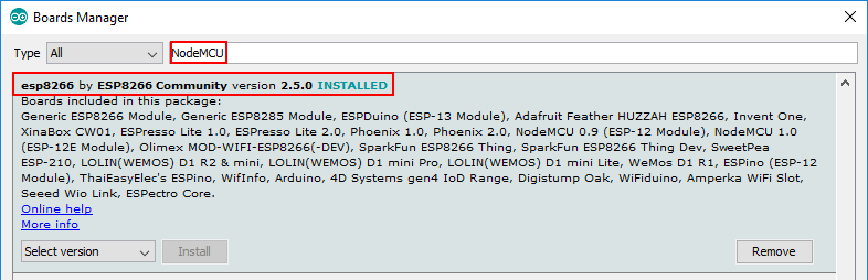
To use the I2C LCD display we have to install the required library “LiquidCrystal_I2C” by Frank de Brabander. You find here an article how to install an external library via the Arduino IDE. After you installed the library successful you can include the library via: #include < LiquidCrystal_I2C.h>.
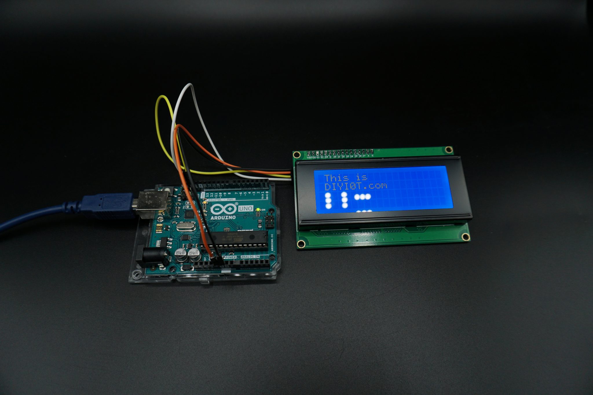
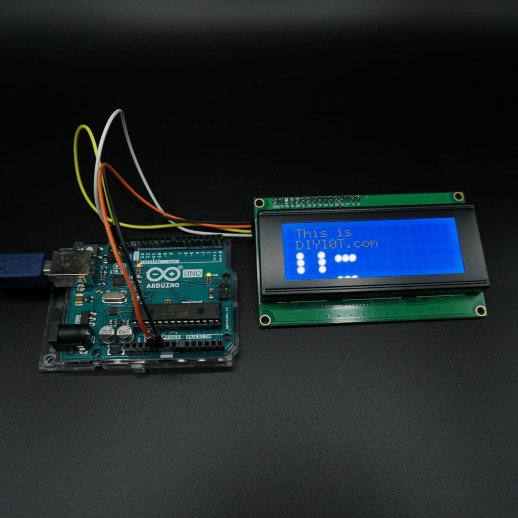
This short example shows you how to use the library to control the LCD display
#include "Wire.h"
#include "LiquidCrystal_I2C.h"

// create an LCD object (Hex address, # characters, # rows)
// my LCD display in on Hex address 27 and is a 20x4 version
LiquidCrystal_I2C lcd(0x27, 20, 4);

void setup()
{
  lcd.init();

  lcd.backlight();
  lcd.setCursor(1, 0);
  lcd.print("This is");
  lcd.setCursor(1, 1);
  lcd.print("DIYI0T.com");
}

void loop(){}
Functions of the LiquidCrystal and LiquidCrystal_I2C library
The LiquidCrystal library has 20 build in functions which are very handy when you want to work with the LCD display. In the following part of this article we go over all functions with a description as well as an example sketch and a short video that you can see what the function is doing.
| LiquidCrystal | LiquidCrystal_I2C | Function LiquidCrystal library | Description |
| x | x | LiquidCrystal() LiquidCrystal_I2C() | This function creates a variable of the type LiquidCrystal. The parameters of the function define the connection between the LCD display and the Arduino. You can use any of the Arduino digital pins to control the display. The order of the parameters is the following: LiquidCrystal(RS, R/W, Enable, d0, d1, d2, d3, d4, d5, d6, d7) If R/W is connected to GND you do not use the parameter in the function: LiquidCrystal(RS, Enable, d0, d1, d2, d3, d4, d5, d6, d7) If you are using an LCD display with the I2C connection you do not define the connected pins because you do not connected to single pins but you define the HEX address and the display size: LiquidCrystal_I2C lcd(0x27, 20, 4); |
| x | lcd.begin() | The lcd.begin(cols, rows) function has to be called to define the kind of LCD display with the number of columns and rows. The function has to be called in the void setup() part of your sketch. For the 16×2 display you write lcd.begin(16,2) and for the 20×4 lcd.begin(20,4). The example below defines the display as 20×4 display and display a text. | |
| x | lcd.init() | Initialization of the I2C display. | |
| x | x | lcd.clear() | The clear function clears any data on the LCD screen and positions the cursor in the upper-left corner. You can place this function in the setup function of your sketch to make sure that nothing is displayed on the display when you start your program. |
| x | x | lcd.home() | This function places the cursor at the upper left corner of the screen. |
| x | x | lcd.setCursor() | If you want to write text to your LCD display, you have to define the starting position of the character you want to print onto the LCD with function lcd.setCursor(col, row). Although you have to define the row the character should be displayed. |
| x | x | lcd.write() | Use the function write to display the values, for example a sensor value. |
| x | x | lcd.print() | This function displays different data types: char, byte, int, long, or string. A string has to be in between quotation marks („“). Numbers can be printed without the quotation marks. Numbers can also be printed in different number systems lcd.print(data, BASE) with BIN for binary (base 2), DEC for decimal (base 10), OCT for octal (base 8), HEX for hexadecimal (base 16). |
| x | lcd.println() | This function displays also different data types: char, byte, int, long, or string like the function lcd.print() but lcd.println() prints always a newline to output stream. | |
| x | x | lcd.cursor() / lcd.noCursor() | Displays or hide the LCD cursor as an underscore (line) at the position to which the next character will be written. |
| x | x | lcd.blink() / lcd.noBlink() | The blink and noBlink function shows or hides a block style cursor that blinks on and off. |
| x | x | lcd.display() / lcd.noDisplay() | This function turn on and off any text or cursor on the display but does not delete the information from the memory. Therefore it is possible to turn the display on and off with this function. |
| x | x | lcd.scrollDisplayLeft() / lcd.scrollDisplayRight() | This function scrolls the contents of the display (text and cursor) a one position to the left or to the right. After 40 spaces the function will loops back to the first character. With this function in the loop part of your sketch you can build a scrolling text function. Scrolling text if you want to print more than 16 or 20 characters in one line, than the scrolling text function is very handy. First the substring with the maximum of characters per line is printed, moving the start column from the right to the left on the LCD screen. Than the first character is dropped and the next character is printed to the substring. This process repeats until the full string is displayed onto the screen. |
| x | x | lcd.autoscroll() / lcd.noAutoscroll() | The autoscroll function turn on or off the functionality that each character is shifted by one position. The function can be used like the scrollDisplayLeft / scrollDisplayRight function. |
| x | x | lcd. leftToRight() / lcd.rightToLeft() | The leftToRight and rightToLeft functions changes the direction for text written to the LCD. The default mode is from left to right which you do not have to define at the start of the sketch. |
| x | x | lcd.createChar() | There is the possibility to create custom characters with the createChar function. How to create the custom characters is described in the following chapter of this article as well as an example. |
| x | lcd.backlight() | The backlight function is useful if you do not want to turn off the whole display (see lcd.display()) and therefore only switch on and off the backlight. But before you can use this function you have to define the backlight pin with the function setBacklightPin(pin, polarity). The following example shows a sketch to turn on and off the backlight. lcd.setBacklightPin(7, NEGATIVE); lcd.setBacklight(1); | |
| x | lcd.moveCursorLeft() / lcd.moveCursorRight() | This function let you move the curser to the left and to the right. To use this function useful you have to combine it with lcd.setCursor() because otherwise there is not cursor to move left or right. For our example we also use the function lcd.cursor() to make the cursor visible. | |
| x | lcd.on() / lcd.off() | This function switches the LCD display on and off. It will switch on/off the LCD controller and the backlight. This method has the same effect of calling display/noDisplay and backlight/noBacklight. |
Blink, Cursor and scroll Display example
To show you some basic examples of the LiquidCrystal and LiquidCrystal_I2C library, you can copy the following example that shows three different functions of the library:
- Show or hide a blinking character field to show the user of your application that for example an input is needed or that an application is loading.
- Show or hide a cursor (“_”) that is useful when you create a menu as navigation bar from the left to the right or from the top to the bottom, depending on a horizontal of vertical menu bar. If you are interested how to create a basic menu with the ESP or Arduino microcontroller in combination with the display, you find here a tutorial.
- Shift all characters to the right for a scrolling display.
The following code shows you the Arduino program to use all three LCD display functions of the library divided into three separate functions. Also the video after the program shows the functions in action.
#include "Wire.h"
#include "LiquidCrystal_I2C.h"

// set the LCD address to 0x27 for a 16 chars and 2 line display
LiquidCrystal_I2C lcd(0x27, 20, 4);

void setup()
{
  lcd.init();
  lcd.backlight();
  lcd.clear();
}

void loop(){
  show_blink();
  show_cursor();
  scroll_display();
  }

void show_blink(){
  lcd.clear();
  lcd.setCursor(0,2);
  lcd.print("Blink is on");
  lcd.setCursor(0,0);
  lcd.blink();
  delay(5000);
  lcd.setCursor(0,2);
  lcd.print("Blink is off");
  lcd.setCursor(0,0);
  lcd.noBlink();
  delay(5000);
}

void show_cursor(){
  lcd.clear();
  lcd.setCursor(0,2);
  lcd.print("Cursor is on");
  lcd.setCursor(0,0);
  lcd.cursor();
  delay(5000);
  lcd.setCursor(0,2);
  lcd.print("Cursor is off");
  lcd.setCursor(0,0);
  lcd.noCursor();
  delay(5000);
}

void scroll_display(){
  lcd.clear();
  lcd.setCursor(0,2);
  lcd.print("Scroll display");
  lcd.scrollDisplayRight();
  delay(1000);
  lcd.scrollDisplayRight();
  delay(1000);
  lcd.scrollDisplayRight();
  delay(1000);
  lcd.scrollDisplayRight();
  delay(3000);
}
How to display custom generated characters?
#include "Wire.h"
#include "LiquidCrystal_I2C.h"

// Set the LCD address to 0x27 in PCF8574 by NXP and Set to 0x3F in PCF8574A by Ti
LiquidCrystal_I2C lcd(0x27, 20, 4);

byte customChar1[] = {
  B01110,
  B01110,
  B00100,
  B11111,
  B00100,
  B01110,
  B01010,
  B01010
};

byte customChar2[] = {
  B01110,
  B01110,
  B10101,
  B01110,
  B00100,
  B00100,
  B01010,
  B10001
};

void setup() {
  lcd.init();
  lcd.backlight();
}

void loop() {
  lcd.createChar(0, customChar1);
  lcd.home();
  lcd.write(0);
  delay(1000);
  lcd.createChar(0, customChar2);
  lcd.home();
  lcd.write(0);
  delay(1000);
  }
Use the following tool to create custom generated characters easy and fast: http://omerk.github.io/lcdchargen/
Important command codes for LCD display
| Sr.No. | Hex Code | Command to LCD instruction Register |
| 1 | 1 | Clear display screen |
| 2 | 2 | Return home |
| 3 | 4 | Decrement cursor (shift cursor to left) |
| 4 | 6 | Increment cursor (shift cursor to right) |
| 5 | 5 | Shift display right |
| 6 | 7 | Shift display left |
| 7 | 8 | Display off, cursor off |
| 8 | 0A | Display off, cursor on |
| 9 | 0C | Display on, cursor off |
| 10 | 0E | Display on, cursor blinking |
| 11 | 0F | Display on, cursor blinking |
| 12 | 10 | Shift cursor position to left |
| 13 | 14 | Shift cursor position to right |
| 14 | 18 | Shift the entire display to the left |
| 15 | 1C | Shift the entire display to the right |
| 16 | 80 | Force cursor to beginning ( 1st line) |
| 17 | C0 | Force cursor to beginning ( 2nd line) |
| 18 | 38 | 2 lines and 5×7 matrix |
Conclusion
I hope you learned a lot in this article. Feel free to test the example sketches with your microcontroller. Do you have any questions regarding this article? Use the comment section below and I will answer your question.