Arduino Nextion Display Tutorial
In this tutorial you learn everything you need to know about the Nextion displays and the differences in the display series.
I show you how to create an interface in the Nextion Editor and how to use the internal programming functions.
This article also contains a basic example to learn the foundations of the display and the interaction with the Arduino microcontroller. An advanced example shows more complex functions of the Nextion displays.
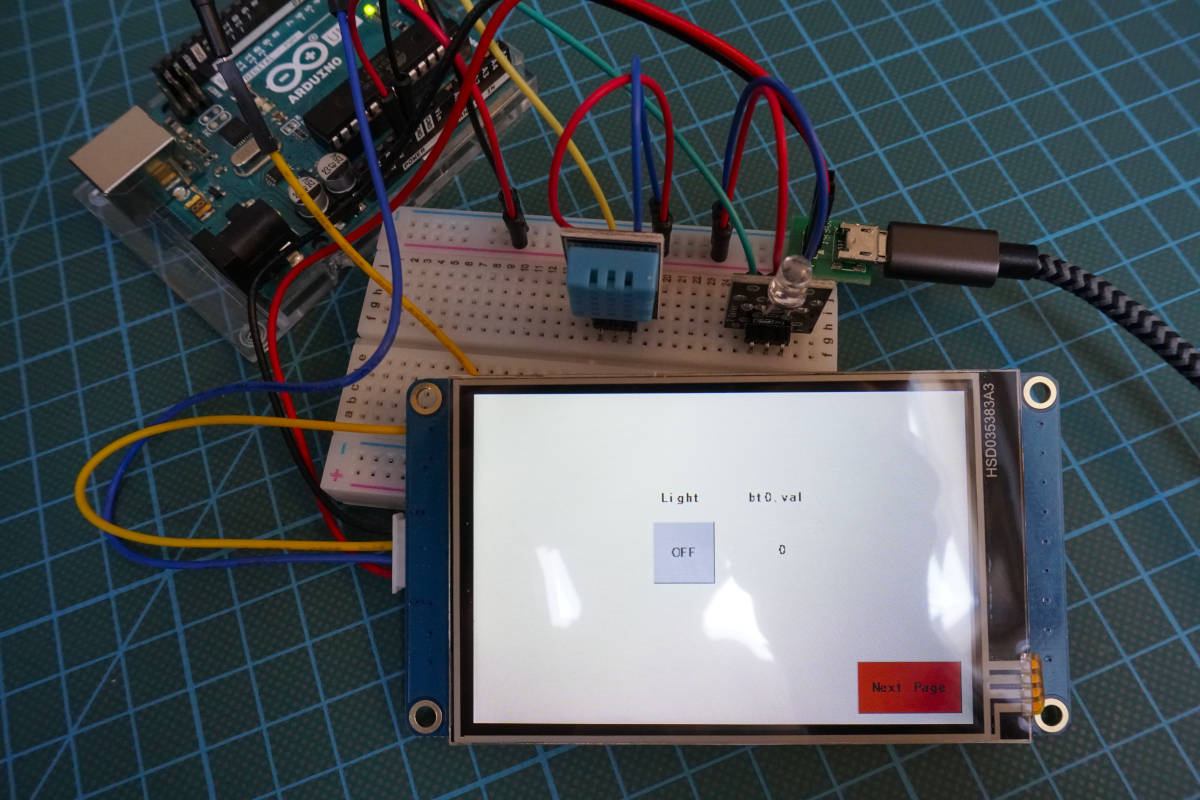
Table of Contents
Nextion is a Chinese company which build, in my opinion, the best HMI (Human-Machine-Interface) displays for DIY microcontroller projects. All of their displays have a touch panel and an onboard processor (MCU) combined with onboard memory. That is why the functions of the Nextion display far exceed that of a normal display. Also the displays has an UART connection, that enables the displays to communicate with all microcontrollers (e.g. Arduino, ESP8266) or single-board computers (e.g. Raspberry Pi).
But why has the Nextion display additional memory onboard?
The display needs all this memory because you can store data directly on the display itself like a background image and you are able to program the display directly without any microcontroller. For example if I push a button, the text and the color of the button should change. Flash memory is used to store different fonts, videos and pictures.
The following table shows the different technical specifications of the Nextion display compared to the ESP8266 NodeMCU V2 and the Arduino Uno regarding computation power and memory size.
3 Different Nextion Displays
Nextion builds 3 different display series: Basic, Enhanced and Intelligent. All three series have the touch function as well as integrated flash, RAM and a MCU. If you order a display, no matter what series, a power supply board (Micro-USB to 5V GPIO) and cables to connect the display are included.
The basic series has everything you need for most projects. The smallest display in the basic series has a 2.4” display and costs $16.4 and the biggest display has a size of 7.0” and costs $74.9.
If you buy a display from the enhanced series you get a more powerful hardware compared to the basic series in terms of MCU, flash storage and SRAM. Moreover the enhances series has an integrated real-time-clock (RTC) module onboard to keep accurate time and EEPROM to store values or strings to the memory of the display during the run-time.
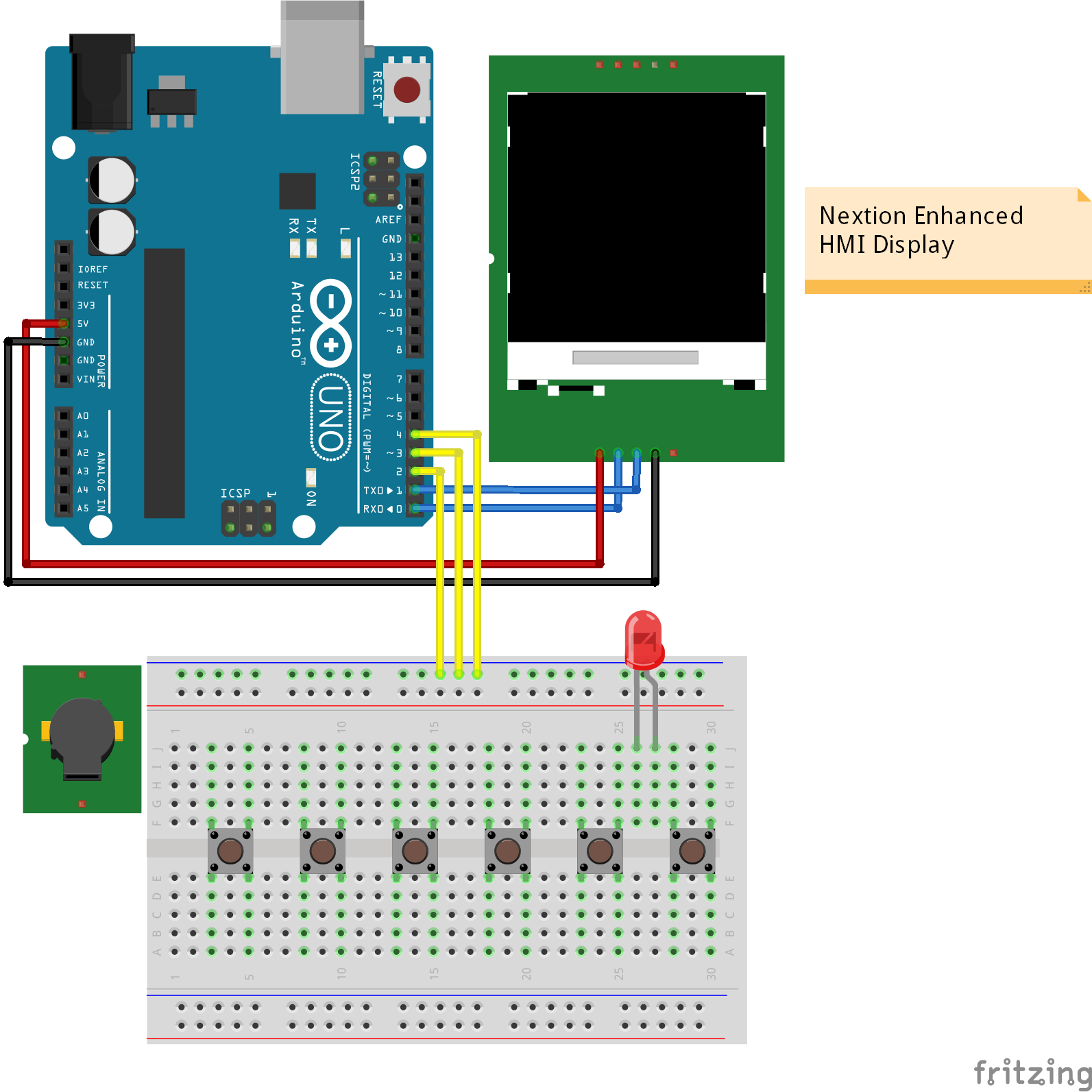
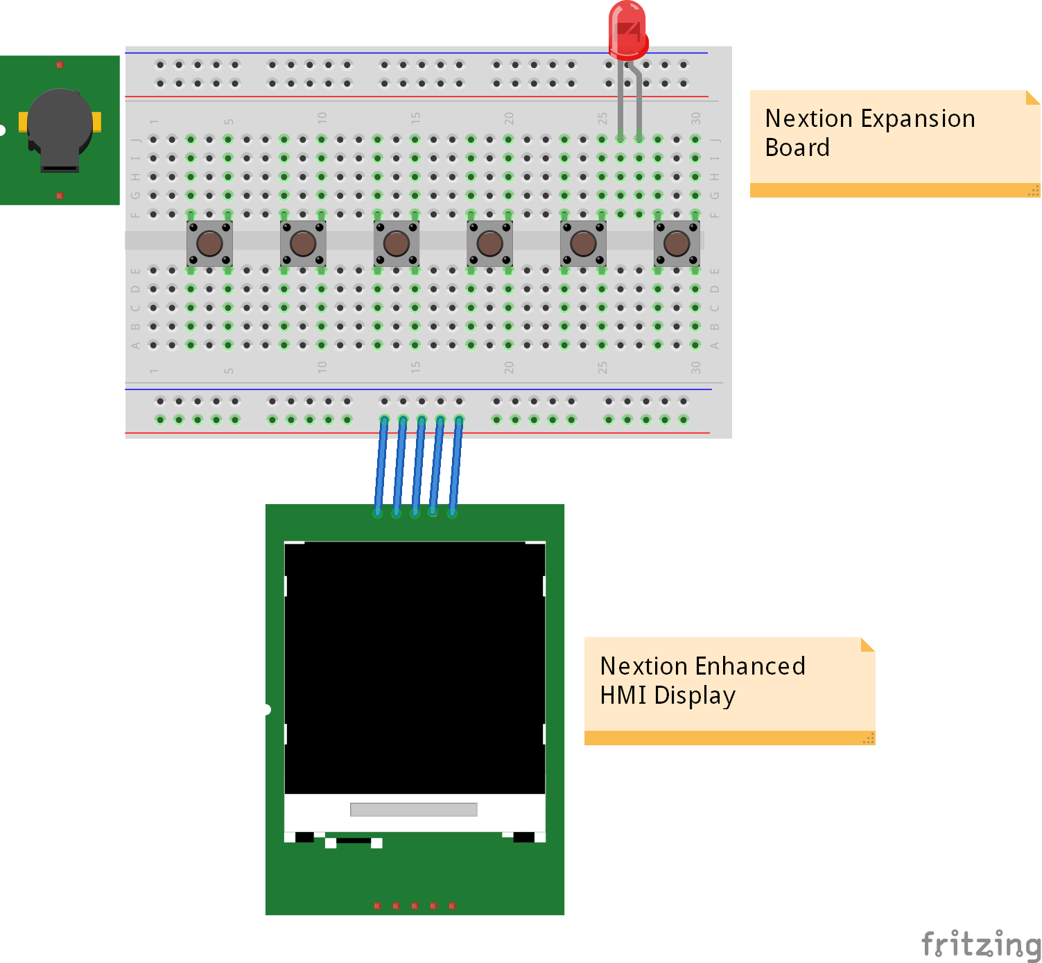
The enhanced models not only have the connection to your microcontroller, but also 8 additional digital pins, of which 4 are PWM capable. These additional pins are used with an Nextion expansion board that includes 6 buttons, 1 LED and 1 piezo buzzer. With the combination of enhanced display and expansion board, you can make basic projects without a microcontroller. In this case you have to program the logic in the display MCU which I also show you in this tutorial. The following picture shows you the difference if you use the expansion board or a microcontroller. The picture is only a schematic sketch and the wiring is not correct.
Nextion display without an expansion board
Nextion display with an expansion board
The intelligent series supports all functions of the enhanced series like the RTC module but also has a much faster MCU build in and also 128MB flash. This allows the intelligent displays to support functions like playing videos and animations, audio support as well as PNG support for pictures. Also the intelligent displays have an anti-aliasing gauge to smooth otherwise jagged lines or textures by blending the color of an edge with the color of pixels around it.
There are multiple objects like a switch component that are only usable for this series. An overview of all components that you can add to your interface is provided in the next chapter of this article.
In each series there are different display sizes available. The following table shows the three different series of displays and the technical specifications. In this tutorial I use the NX4832T035 from the basic series, that have a 3.5” display.
R – Touch screen type: R = resistive touch, C = capacitive touch
The following table gives you an overview of all components and parts that I used for this tutorial. I get commissions for purchases made through links in this table.
Building Interfaces with the Nextion Editor
Now we want to know how to build a HMI with the Nextion display. This is done by the Nextion Editor, a free GUI (graphical user interface) development software. You can download the latest version of the software on the Nextion website.
When you start the editor you see the same panels like the following picture. The difference is, that I already created a project to show you the content of the different panels.

The first thing we want to do is to create a new project. The following steps guide you through is process.
- First we click the New button on the Toolbar and select a folder where to save the project.
- A new window opens and you have to select your display. First you select the series: Basic, Enhanced or Intelligent and then the size of the display. Hint: On the site of the package where the display was in, you find the corresponding number like: NX4832T035 in my case.
- Then you can select the display direction: vertical or horizontal and confirm all setting by pressing the OK button.
After we create the project you have to know the basic functions of the Nextion Editor. From the picture above you see that there are 8 planes that are described in the following section:
Main Menu: In the Main Menu you find standard options and settings. For example you can open, save and close projects, find the general settings and look for updates.
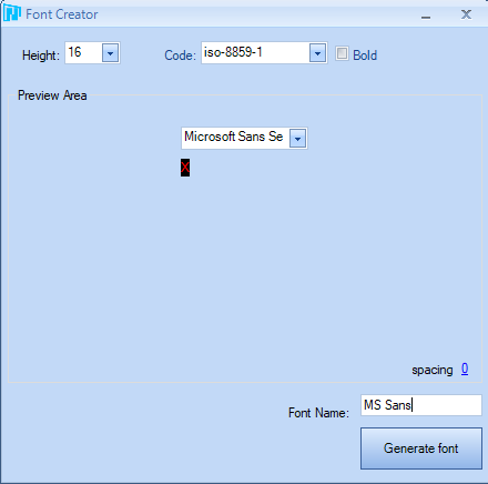
- In the tools category you can add new fonts with the font generator. In the generator you can choose from different fonts and select the height. It is useful to create more than one font for your project.
Toolbar: In the Toolbar you can also open, save or create a new project. In the second line there are multiple functions to align the components of the toolbox. Also you find other functions that we will use:
- Compile: Before you transfer the project to the display you have to compile the current code.
- Debug: The debug window is a good option to check how to display will look like. Also you can check implementations that are programmed directly on the display.
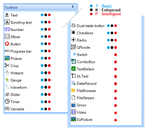
Toolbox: In the toolbox are all components that you can add to your project. By clicking on a component it is added to the design plane. There are some advanced components that are only available for the intelligent series. The following picture shows what components are available for the different series of displays.
Resource Plane: In the resource plane you add pictures, fonts as well as video and audio data that is included in the program files.
Event Code: In this section you can define program code that is executed when a component is used. For example you can define what should happen when a button is pressed and what should happen when this button is released.
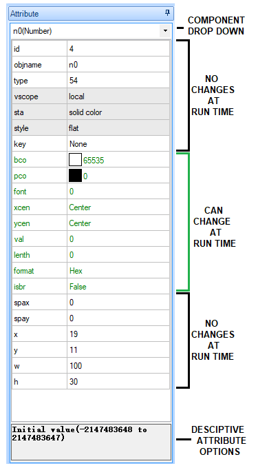
Toolbox Plane: In the toolbox plane you define the attributes of the selected component. These attributes are separated into two categories:
- Can change at run time
- Cannot change at run time
The following pictures shows which attributes belong to which of the two categories. The most important attributes which are also needed for the Arduino program code are the “id” and the “objname”.
Page Plane: With the Nextion displays you can create virtual pages where you can show different information. You HMI needs at least one page that is added when you create a new project. Also you can export and import pages so save time and reuse different kind of pages.
Design Plane: The design plane is your main window where you layout the interface with different components that you add with the toolbox.
If you want full detailed information about all features of the Nextion Editor, you can visit the editor guide.
The following video shows how I create a new project for my display and add a font as well as some components.
In the video you see the following steps that I make. These basic steps help you to get your first interface running.
- I created a new project and save the project on my disk.
- After the project is created, I choose the right display model and the select the display direction.
- In the resource plan I could add a previous created font but I wanted to create new new one via the Font Generator in the setting menu bar.
- The created font is saved to the disk and added to the current project.
- For this example I create a text field and changed the text and the maximal text width from 10 to 30. If I had not created a font previously, then I would get an error message.
- I created also a button and set the text to button, how creative 🙂
- The last step is to check if everything is running in the debugger.
How to get the interface from the Nextion Editor to the display?
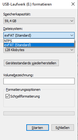
The short answer would be via a micro SD card, but in reality it was a little bit trickier. The basic requirement for the Nextion display is that the SD card has to be in FAT32 format. First I tried to use a 64 GB micro SD card but unfortunately when I tried to format the card in Windows 10 there was no option to format the 64 GB micro SD card to FAT32.
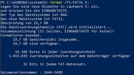
Also I tried to format the SD card via the windows PowerShell but this did not work either and I don’t wanted to install a third party application only to change the format of the SD card once.
But I was lucky that I found a 32 GB SD card and the formatting via the PowerShell worked this time with the command: format /FS:FAT32 E: (E is the name of the volume of the SD card)
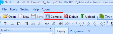
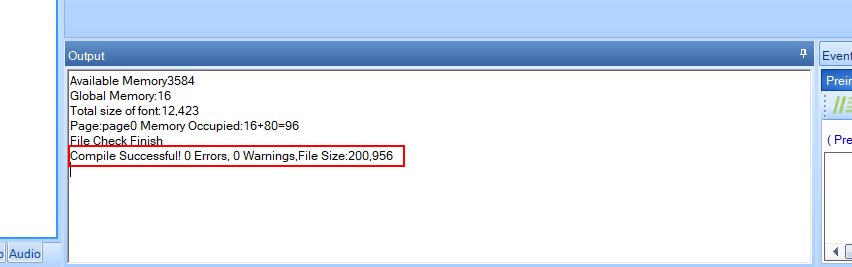
After the SD card is ready we have to compile our code to make sure that the compiler does not find any errors. You find the compile button ins the Toolbox and the output of the compiler in the output box at the bottom left in the Nextion Editor.
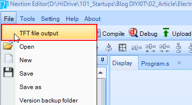
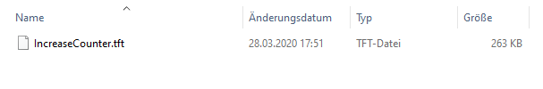
The next step in the Nextion Editor is to export the TFT file to the micro SD card. Click on File in the main menu and select TFT file output. Now you choose your FAT32 formatted micro SD card and export the file to the card. If you wish, you could check if the TFT file is on the SD card.
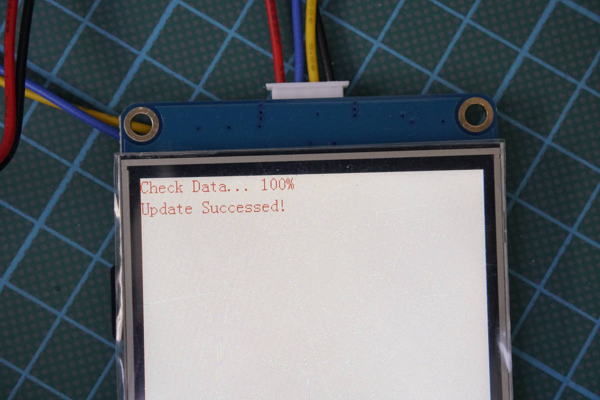
The last step is to place the SD cart into the SD card slot of your Nextion display. After powering the display up, you see that the display recognizes the SD card and loads the file in the internal memory of the display.
Now you disconnect the display from the power source and remove the sd card after transferring the .tft program.
The next step is to prepare the Arduino IDE to enable the connection between the Arduino or ESP8266 based microcontroller and the Nextion display.
Arduino IDE preparation for Nextion Displays
Good news: the Nextion developers created a library for Arduino and Raspberry Pi that makes the coding much easier. The bad thing is, that this library is not included in the Arduino IDE library search. Therefore we install the library manually in 4 steps:
- Download the Arduino library for Nextion Display as ZIP file from the official github repository to a local folder of your choice.
- Go to your download folder and unzip the zip file. You should get a folder named: ITEADLIB-Arduino-Nextion-master
- Rename this folder to: ITEADLIB_Arduino_Nextion.
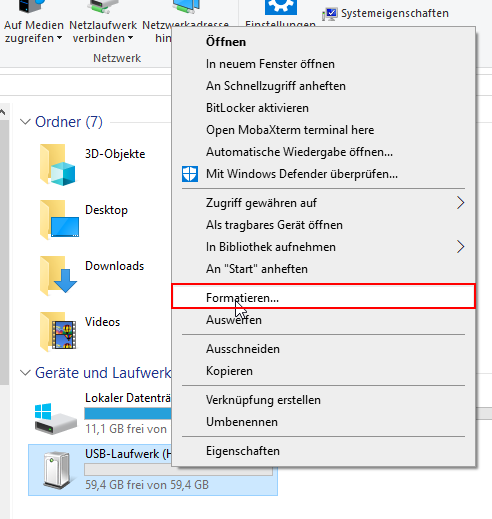
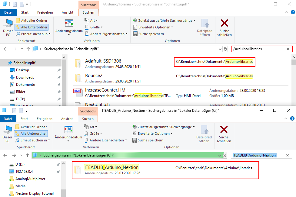
- Move the ITEADLIB_Arduino_Nextion folder to your Arduino IDE installation libraries folder. If you do not know how your library folder is located you can search for Arduino/libraries and will find the folder, see the following picture.
The Nextion library is configured for the Arduino Mega. If you use the Arduino Mega for this project, you can skip the next step. But if you use for example an Arduino Uno, like me, we have to change the configurations of the library because the Arduino Mega has two hardware serials and the Arduino Uno for example only one.
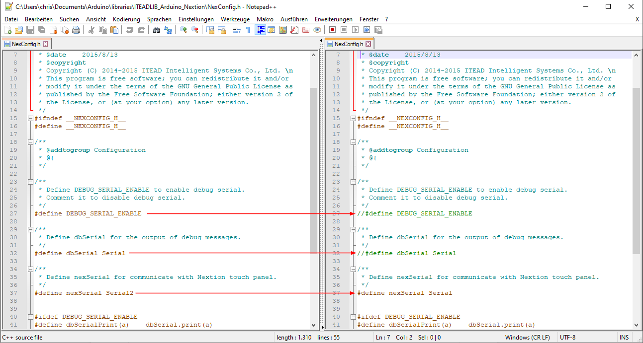
In the library folder open the NexConfig.h file and change the following three lines:
- Line 27: comment line with //
- Line 32: comment line with //
- Line 37: change Serial2 to Serial
Now everything is setup and we can create our first basic example. After the basic example I show you a more advanced example where we also use the program function of the Nextion display itself.
Basic Nextion Example – Increase Counter
The first example is an easy basic example where you learn how to add buttons and use a number field to make a counter with a reset button. This example has only one page to keep it simple. If you are new to the Nextion display, this tutorial is right for you, but if you are already advanced, you can jump to the next example where I show you a more complex example.
You can download every file I use in this example with the following download button. You download a zip file that includes the Nextion Editor TFT file, the used fonts, a picture and the Arduino script.
If you have not already started your Nextion Editor, you can open it now. Like in the video I showed you at the beginning of this tutorial, the first step in a new project is to select your Nextion display and select the horizontal or vertical display direction. In the second step you can create one or more fonts for this project. I created two fonts, one with a height of 16 and the second with a height of 32 to display text a little bit bigger.
I also want to display a picture in the display. Therefore I select picture in the resource plan and with the red plus sign I added the logo of the DIYI0T bog as picture. To display the picture on the display, I choose picture in the toolbox to add a picture frame to the interface. Now you have assign the right picture ID to the frame. Therefore set the pic setting in the toolbox plane to 0.
I also add all other components that we need from the toolbox:
- 1 text field
- 2 buttons
Let us summarize all components of this project in the following table. If your ID is different, it does not matter, but you may have to change the Arduino script which we discuss later in this tutorial.
To change the shown text for the two buttons, we click on a button and in the toolbox plane under txt we set the text to “+” and “Reset”.
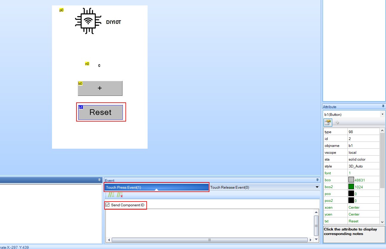
Now comes the most important part of this example. We have to make sure that the Arduino is informed via UART when the two buttons are pressed. Generally there are two options when the display sends the signal to the Arduino:
- The button is pressed: Touch Press Event → PushCallback
- The button is released: Touch Release Event → PopCallback
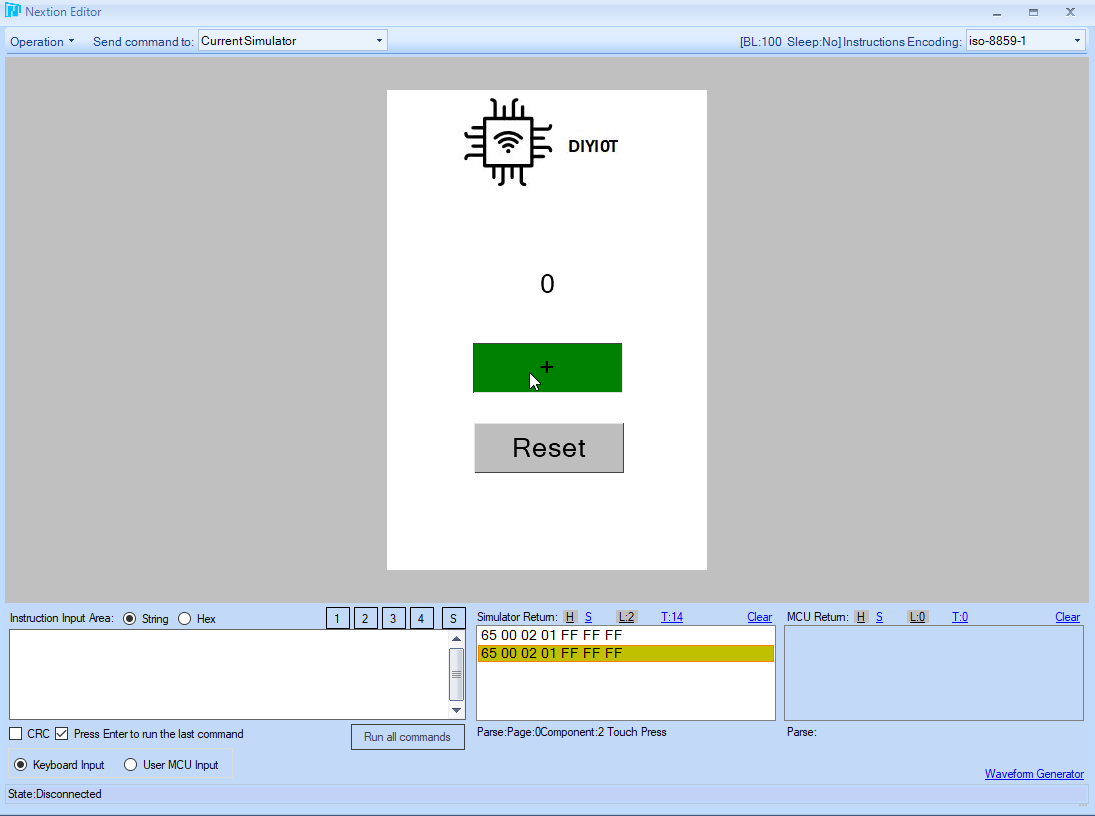
Depending on your selection of this option, also the Arduino code will change. I explain the changes in the programming part. I want to inform the Arduino when the button is pressed. Therefore I checked the checkbox “Send Component ID” in the event code of the buttons that you see in the following picture.
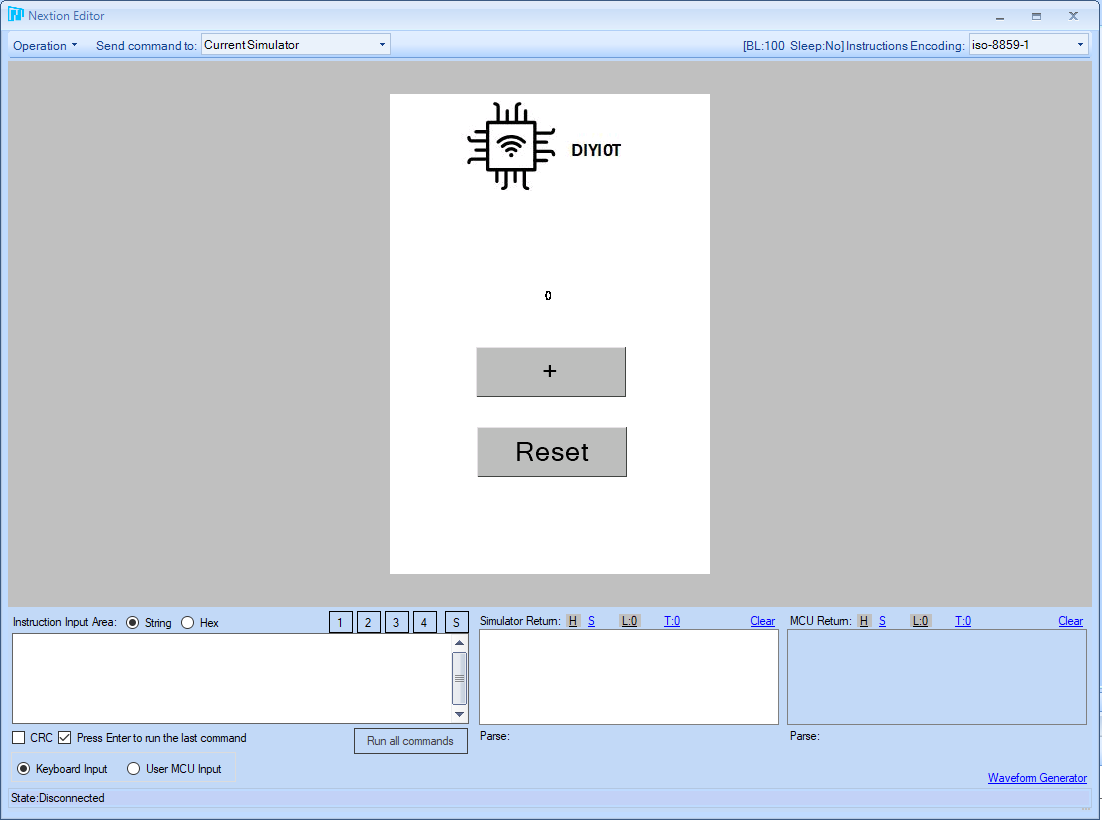
Now everything should work correct and we check the output with the debugger. You should have an interface like the following picture.
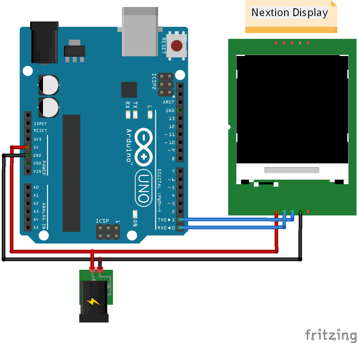
The following picture shows the UART connection between the Nextion display and the Arduino Uno which I use for this example. In this project the power supply is provided via micro USB and the Power Supply Test Board which is part of the Nextion package.
After the interface is loaded to the displays and all parts are connected, we create the Arduino script.
#include "Nextion.h"

// Nextion Objects
// (page id, component id, component name)
NexButton b0 = NexButton(0, 1, "b0");
NexButton b1 = NexButton(0, 2, "b1");
NexNumber numberbox = NexNumber(0, 4, "n0");

// Register objects to the touch event list
NexTouch *nex_listen_list[] = {
  &b0,
  &b1,
  NULL
};

//Increase the number
void b0PushCallback(void *ptr) {
  uint32_t number;
  numberbox.getValue(&number);
  number++;
  numberbox.setValue(number);
}

//Reset the number
void b1PushCallback(void *ptr) {
  uint32_t number;
  numberbox.getValue(&number);
  number = 0;
  numberbox.setValue(number);
}

void setup() {
  Serial.begin(9600);
  //Initialize Nextion Library
  nexInit();

  // Register the push/pop event callback function
  b0.attachPush(b0PushCallback, &b0);
  b1.attachPush(b1PushCallback, &b1);
}

void loop() {
  //When push/pop event occured execute component in touch event list
  nexLoop(nex_listen_list);
}
Like in every other script, the first thing we have to do is to include all the libraries we need. For this example we only need the Nextion library. Then we define the Nextion objects based on the added components in the editor. The logic to add an object is the same every time, which shows the following table.
- Object: The object is the library name of the Nextion component that you added to your editor. For example the button component of the editor is the NexButton object. You simply add “Nex” in front of the component.
- Object Name: You can choose the object name that is used to call the object in later stages of the script.
- Page ID: The ID of the page, the component is located in the editor.
- Component ID: The ID of the component that you can look up in the toolbox plane.
- Component Name: The name of the component that you can also look up in the toolbox plane.
The following table shows the matching between the component of the Nextion Editor and the object of the Nextion Arduino library.
The next part in the script is to create a touch event list called nex_listen_list to define what objects trigger an event. In this example we include the two buttons and also NULL is included every time to this list.
Now for each element of the nex_listen_list, we have to create a function, that is called when the event for this object is triggered. The first function we create is the function for b0 that increase the number of the display. I like to give my functions a predefined structured name. That is why I call the function b0PushCallback.
The function is called for the b0 object and in the Nextion Editor we defined that the component should have a touch press event and not a touch release event. The touch press event is the push callback and the touch release event would be a pop callback.
Inside the function, the logic of the script is pretty easy. First we create a variable number. Inside this variable we store the current value of the numberbox object which is the displayed number in the number component. The function to read the number is getValue. After we increased the variable, the value of the number component is set to the increased variable with the setValue function.
The function for the second button b1 is nearly the same. The only difference is that we do not increase the variable, but we reset the variable to 0.
After the two functions are defined, we create the setup function in the Arduino IDE. Because we use the UART communication between the Nextion display and the microcontroller, the baud rate is set to 9600 which is recommended by Nextion. Also the Nextion library is initialized in the setup function. The last part of the setup function is to register the push or pop event callback functions. The callback function asks: When do I have to executed the predefined functions? Therefore we attach the push event to both objects and define that if the event occurs, the predefined functions should be called.
If we did not defined touch press events but touch release events, the functions would be: b0.attachPop(b0PopCallback, &b0);
The loop function contains only one line of code. In this line of code we define that in every cycle we monitor the events of the touch event list. If an event happens, the callback function of the setup function is executed.
The following video shows how the number of the counter increases and can be reset with the reset button.
Advanced Nextion Example – Light and Temperature
This advanced example shows how to use the internal programming capabilities of the Nextion displays and also how to control lights and visualize the temperature and humidity of a DHT11 sensor module.
You can download all files used in this example (Nextion Editor TFT file, fonts, Arduino code) as zip file with the following download button
First we create the interface in the Nextion Editor. Therefore create a new project and select your display model. For this advanced example I use the landscape orientation of the display. You can use the already created font from the basic example or create a new one. The following two pictures show the interface we want to build with two pages.
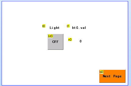
Page 0
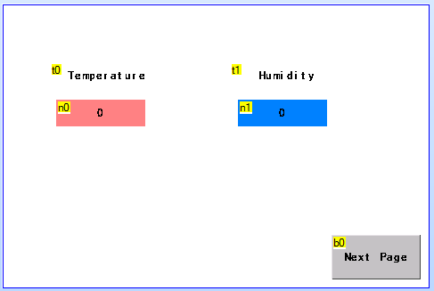
Page 1
On the first page we create two text boxes which remain static in the whole example. With the toolbox panel we change the text inside the text boxes to “Light” and “bt0.value”.
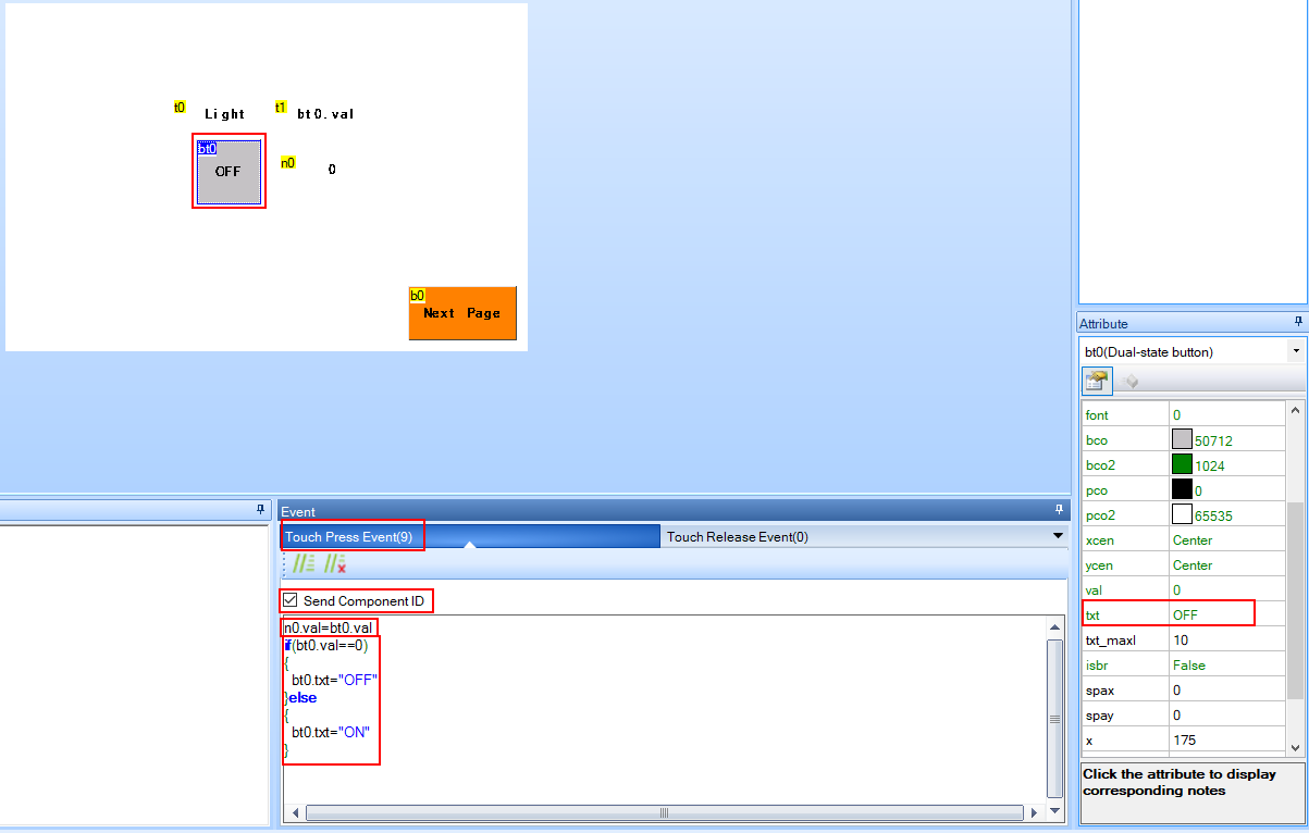
Under the light text we create a dual-state button and change the text to “OFF”. With this button we want to turn a light on and off. Depending on the status of the light, I want to change the text of the button. This could be done via the microcontroller with the functions getText and setText but we want to change the text direct with the programmable capabilities of the display. Therefore in the event code panel of the editor we create a simple if equation that takes advantage of the changing value of the dual-state button. If the dual-state button is not pressed, the value is 0 and the text of the button is set to “OFF”. But in all other cases, when the button is pressed and the value is 1, the text changes to “ON”.
The change in the value of the dual-state button should also be visualized in a number component. We create a new number component under the other text field. To display the value of the dual-state button, we simply set the value of the number component to the value of the dual-state button when the touch press event occurs.
Also we have to send the component ID to the microcontroller when the button is pressed to turn on the light.
The following picture shows the code in the event panel of the dual-state button.
The last component that we add to page 0 is a button to get to the next page. We create a new button and place it to the bottom right of the screen. You can change the color for the button like I did in the toolbox plane and change the text to “Next Page”. Of cause we have to add the function to change the page, when the button is pressed. This is done by the touch press event you see in the following picture. The command is page with the page ID of the target page.
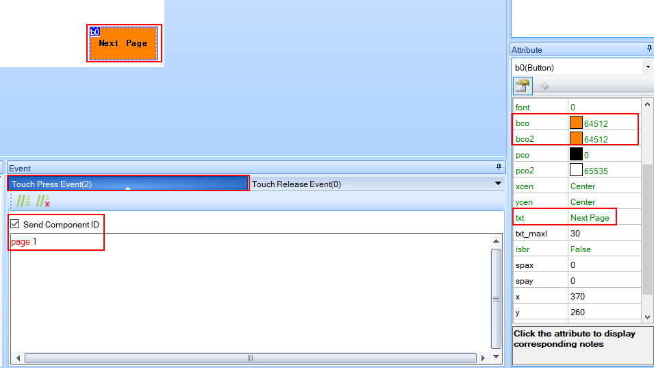
I also want to send the component ID when the next page button is pressed, because I use this trigger to update the temperature and humidity on the second page.
On the second page we create two text fields and two number components. Each text field displays the sensor value that is shown in the number components. For fun I also changed the background color of the number components.
Because I want to go back to page 0 from page 1, I created a button to get back to page 0. The code is the same, but the ID of the page is 0.
Now every site and component is set up and you can test if everything is working with the debug function of the Nextion Editor. After everything is working you can compile the project and export the TFT file to the micro SD card.
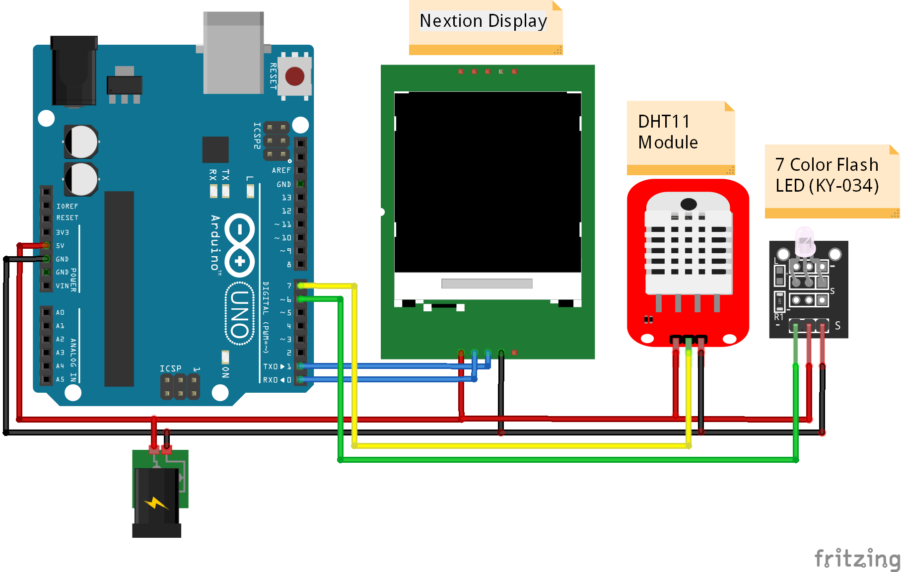
The next task is to connect the display with your microcontroller and all other components. I use my Arduino Uno as microcontroller, the DHT11 sensor module to measure the temperature and humidity as well as the 7 color flash LED (KY-034) as light. The following fritzing picture shows how to connect all the devices.
Because we implement a whole bunch of the functionality of the interface directly in the Nextion Editor, the Arduino script is not very complicated.
#include "DHT.h"
#include "Nextion.h"

#define DHT11modulePIN 7        // define the digital I/O pin
#define DHT11moduleTYPE DHT11   // DHT 11 module
#define LEDPIN 6                // define the digital I/O pin

DHT dht11module(DHT11modulePIN, DHT11moduleTYPE);

// Declare Nextion objects
// The the following informations from Nextion Editor
// (page id, component id, component name)
NexDSButton bdslight = NexDSButton(0, 2, "bt0");
NexButton nextpage0 = NexButton(0, 1, "b0");
NexNumber ntemp = NexNumber(1, 4, "n0");
NexNumber nhum = NexNumber(1, 4, "n1");

// Register objects to the touch event list
NexTouch *nex_listen_list[] = {
  &bdslight,
  &nextpage0,
  NULL
};


void bdslightPushCallback(void *ptr) {
  uint32_t dual_state;
  bdslight.getValue(&dual_state);
  if(dual_state)
  {
      digitalWrite (LEDPIN, HIGH); // set the LED on
  }
  else
  {
      digitalWrite (LEDPIN, LOW); // set the LED off
  }
}


void nextpage0PushCallback(void *ptr) {
  float h11module = dht11module.readHumidity();
  float t11module = dht11module.readTemperature();
  nhum.setValue(h11module);
  ntemp.setValue(t11module);
}


void setup() {
  Serial.begin(9600);
  pinMode (LEDPIN, OUTPUT);
  dht11module.begin();

  nexInit();
  // Register the push/pop event callback function
  bdslight.attachPush(bdslightPushCallback, &bdslight);
  nextpage0.attachPush(nextpage0PushCallback, &nextpage0);
}

void loop() {
  nexLoop(nex_listen_list);
}
At the beginning of the Arduino script we include the Nextion and DHT libraries and define the pins where the DHT11 module and the LED is connected. With the DHT11 model type and the pin, we create a dht11module object.
Like in the beginner example we create 4 Nextion objects:
- One dual-state button to turn the LED on and off
- One button from the page 0 to update the temperature and humidity
- Two number objects to display the temperature and the humidity of the DHT11 sensor module
From all four objects only the dual-state button and the button to get to the next page trigger an event and are therefore added to the touch event list.
Now we define the functions for the touch event list. The first function for the dual-state button creates a variable to store the value of the dual-state button. If the value is 1, the light is turned on via the digitalWrite function and otherwise the value has to be 0 and the dual-state button turns off the LED.
The function for the next page button on page 0 reads the temperature and the humidity and set the corresponding values of the number objects to the measurements.
In the setup function the baud rate is set to 9600 and the pin of the LED is defined as output. Then the DHT11 object and the display is initialized. Like in the basic example the callbacks of the objects from the touch event list are registered as push callback.
The loop function contains only the line of code to define that in every cycle we monitor the events of the touch event list. If an event happens, the callback function of the setup function is executed.
The following video shows how the light in turned on and off. Also the temperature and the humidity is displayed in the second page of the interface.
I hope you learned a lot about the Nextion display in this tutorial. If you have any question regarding the Nextion displays in general or the examples in this article, use the following comment section to ask your question. I will answer the question as soon as possible.
Excellent, très bien commenté 🙂
Hi Denis, thank you for your response. I hope you find the Nextion Display as cool as I find this display.
Excelent tutorial. Very well explained. You helped me to understand te whole process.
Thank you so much.
Hi Jaime,
thx for your feedback that the whole process is well explained 🙂
Hi Jaime,
I have a few questions.
Can the Nextion display use alpha blending for rectangles and pictures? Can I specify the line with for lines and circles, and arcs? Are the lines and circles antialiased?
Regards, Jack
Hi Jack, so far I know you can not use alpha blending for rectangles and pictures. Also you can not draw free lines or circles. However you choose a button, a checkbox or radio button as predefined object. Therefore you do not have to draw your own objects. Nextion displays support anti-aliasing for fonts.
Hi, great article thanks! Do you have issues with the nextion missing key presses when your arduino code gets more complicated? I find mine will miss when I have pressed a button if the arduino is busy running other code. There doesn’t seem to be a fix for this from what I can see?
Hi Jonny, in my small examples I do not see this problem. What baud rate are you using? Maybe you can fix this problem with the attachInterrupt() function: https://www.arduino.cc/reference/en/language/functions/external-interrupts/attachinterrupt/
I did not try out this function but maybe you find a way that the Arduino code is always listening on the UART communication between the Arduino microcontroller and the Nextion display.
I can’t force the button (b) with two images attached to it (pic & pic 2) to change the displayed image from pic to Pic2 and return the previous pic value after clicking. Can anyone help?
Superb work! Not that easy at first, but luckily there are people like you who explain it clearly. Thank you. (Dankie) (-8
Hi, i used your example to try and get a hang of using the nextion screen. After some messing around (I used an arduino Due which doesn’t support SoftwareSerial so I had to comment out the part of NexUpload.cpp that references SoftwareSerial) I still couldn’t get the screen to display your example. Turns out that I didn’t think of removing the sd card. It might be useful to add that part to your tutorial, “remove the sd card after transferring the .tft program!”
Hi Luc, you are absolute right. I forgot this little but meaningful detail and added it into the article. Thx for the comment.
Thanks your example.
I have a question.
When i turn on light, and press next page.
and after that, once again press back page.
Light button initialize I mean panel button off but light still turn on.
So how can i programming? when i press backbutton, I hope turn on button.
Let me know!!!
this is my new program.
#include
#include “Nextion.h”
dht DHT;
#define DHT11_PIN 7
// #define DHT11moduleTYPE DHT11 // DHT 11 module
#define LEDPIN 6 // define the digital I/O pin
uint32_t dual_state;
// Declare Nextion objects
// The the following informations from Nextion Editor
// (page id, component id, component name)
NexDSButton bdslight = NexDSButton(0, 2, “bt0”);
NexButton nextpage0 = NexButton(0, 1, “b0”);
NexButton nextpage1 = NexButton(0, 2, “b0”);
NexNumber ntemp = NexNumber(1, 4, “n0”);
NexNumber nhum = NexNumber(1, 4, “n1”);
// Register objects to the touch event list
NexTouch *nex_listen_list[] = {
&bdslight,
&nextpage0,
&nextpage1,
NULL
};
void bdslightPushCallback(void *ptr) {
bdslight.getValue(&dual_state);
if(dual_state)
{
digitalWrite (LEDPIN, HIGH); // set the LED on
}
else
{
digitalWrite (LEDPIN, LOW); // set the LED off
}
}
void nextpage0PushCallback(void *ptr) {
DHT.read11(DHT11_PIN);
float h11module = DHT.humidity;
float t11module = DHT.temperature;
nhum.setValue(h11module);
ntemp.setValue(t11module);
}
void nextpage1PushCallback(void *ptr) {
// Serial.println( &dual_state );
bdslight.setValue(dual_state);
}
void setup() {
Serial.begin(9600);
pinMode (LEDPIN, OUTPUT);
nexInit();
// bdslight.getValue(&dual_state);
// Register the push/pop event callback function
bdslight.attachPush(bdslightPushCallback, &bdslight);
nextpage0.attachPush(nextpage0PushCallback, &nextpage0);
nextpage1.attachPush(nextpage1PushCallback, &nextpage1);
}
void loop() {
nexLoop(nex_listen_list);
}
Nice and simple explanation. Well done. Thanks.
Hi, I’m glad you liked the article and hope that you will realize a cool project with the knowledge.
hi,
i have basic model of nextion (NX3224T024)
i want to create a two page project, where after power on page one should remain their for 2sec and then it should move on to next page
can you please help?
Hello Rohan. On the landing page, click the “timer” tab in the “toolbox” section on the left. Type “page page1” in the section where the code is written under “event”. Enter 2000 in the “tim” section of the settings in the “Atturibute” section on the far right. it happens that way you want.
Hello there. You explained it very well. first of all thanks. I have a question. How can we assign nextion number to arduino variable? as an example: How can we write a number that we have changed with + and – to the variable named “number” in arduino?
Can anyone tell me if I can connect the Nextion Intelligent 7 inch screen (NX8048P070-011C) directly to an Arduino Due. Are both using 3.3 volts serial lines or do I need to level shift?
Great Explanation of the whole process Can you please explain the function of getvalue and setvalue ?
Hi, thank you very much for an excellent tutorial. I ran into a problem that the display and Uno was not communicating. After reading up a bit I inserted the line bauds=9600 in the Preinitialize Event and it worked properly. Thank you very much.
Hi Marhinus,
yes the baud rate has to be 9600 for the Nextion Display. Good to hear that now everything is working fine.
This example works 100%…Had a bit of a headache with DHT library…but got it fixed…Need more training with this. Can you please suggest where to look?
Othervise…great tutorial. Respect to you, Sir.
I’m looking for an example sketch to convert the rtc clock to the current time of the NX3224K028-011.
Please reply. I haven’t made it yet. The clock itself is on the screen and the seconds are running.
Bonjour et merci pour votre tuto et de votre partage, comment faire pour garder l’état des valeur de la page 1 quand t’on Switch d’une page à l’autre ?
cordialement